Big Earls Farmboy #758

Home Model Engine Machinist Forum

Help Support Home Model Engine Machinist Forum:

This site may earn a commission from merchant affiliate links, including eBay, Amazon, and others.
Well my gut said to just start again so that's what happened - I am not where I would like to be but I did more than I expected today. Apologies if some of this feels like Top Gear on Dave.

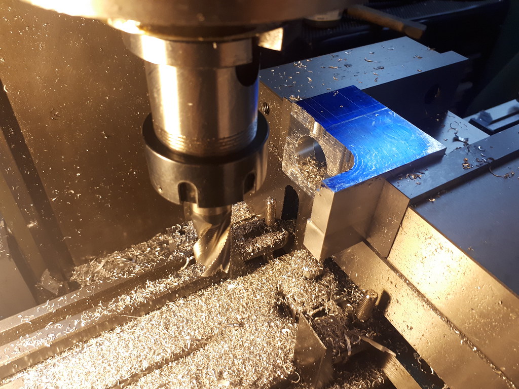
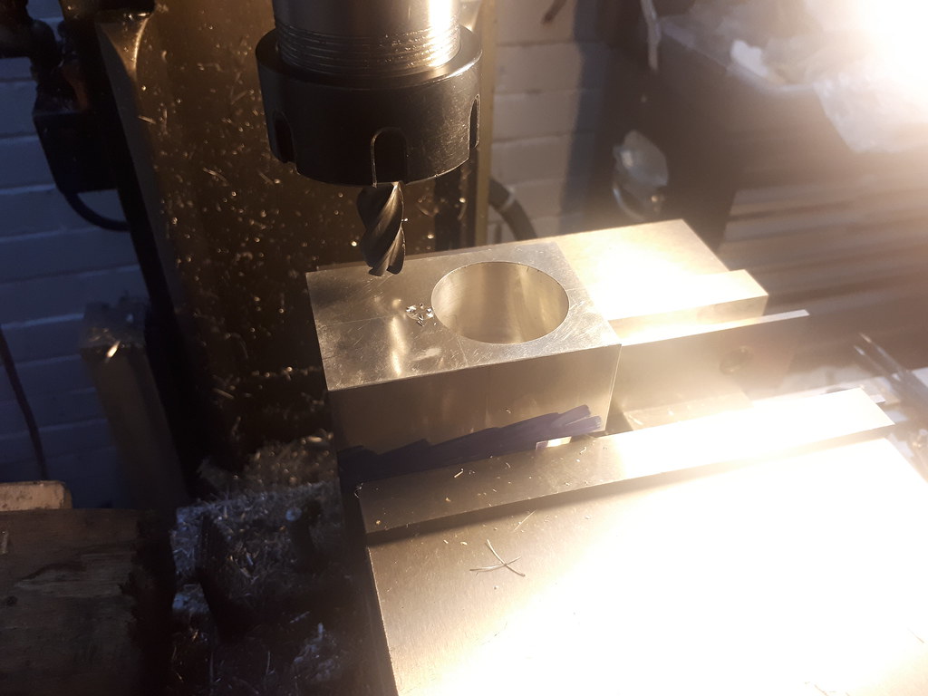
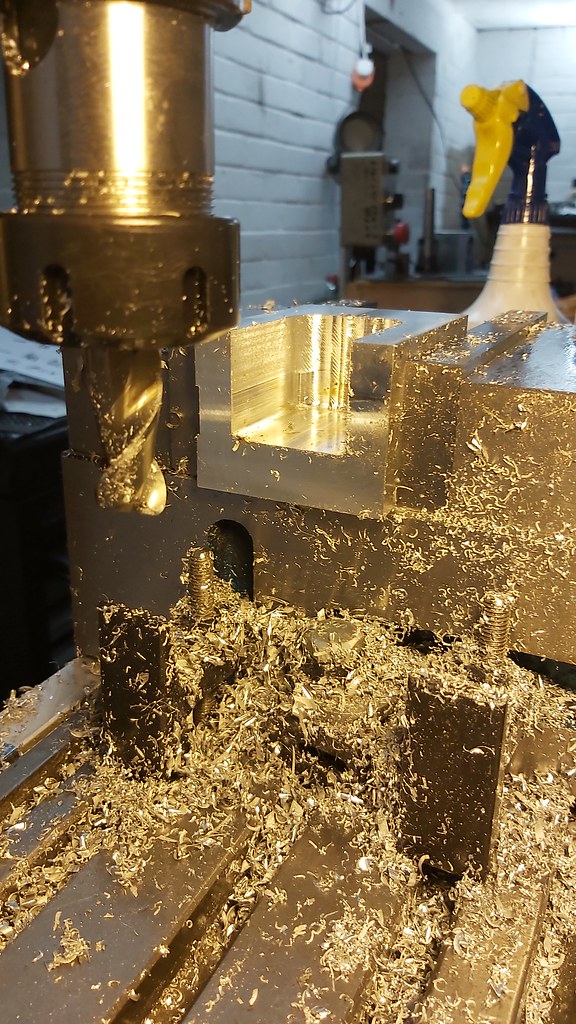
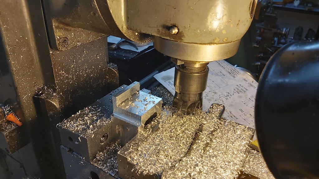
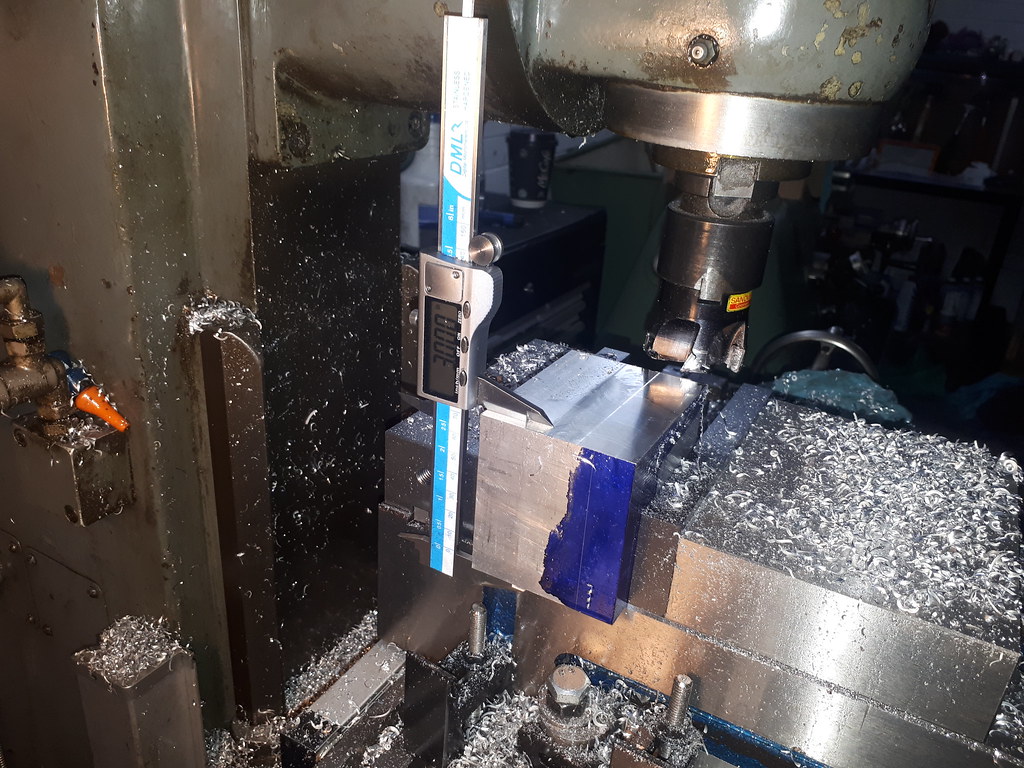
Whilst I was starting again squaring off the stock, I decided to square off 3 sides of the remaining chunks which will later become the frame rear and water hopper.
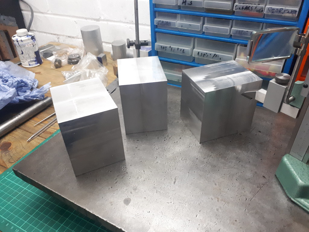

In the interest of saving money by buying the stock at one size, it shows just how much needs to be removed!
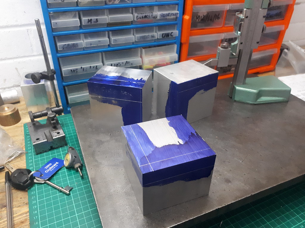

Placed next to the scrap piece you can get a sense of what about needs to be taken off
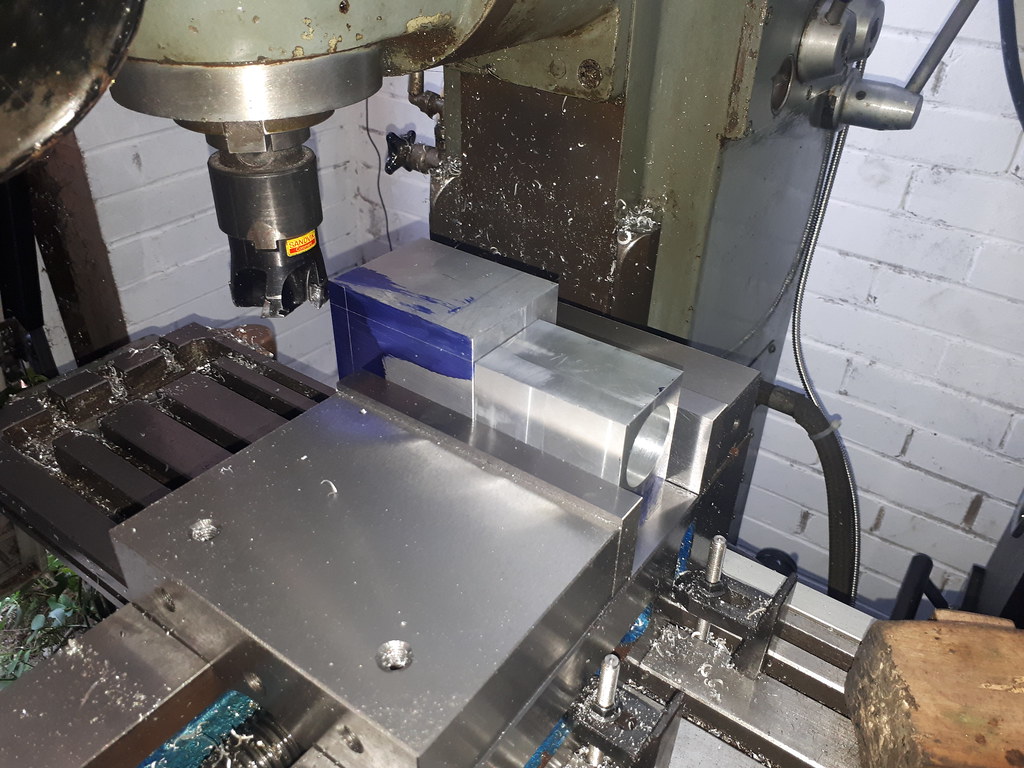

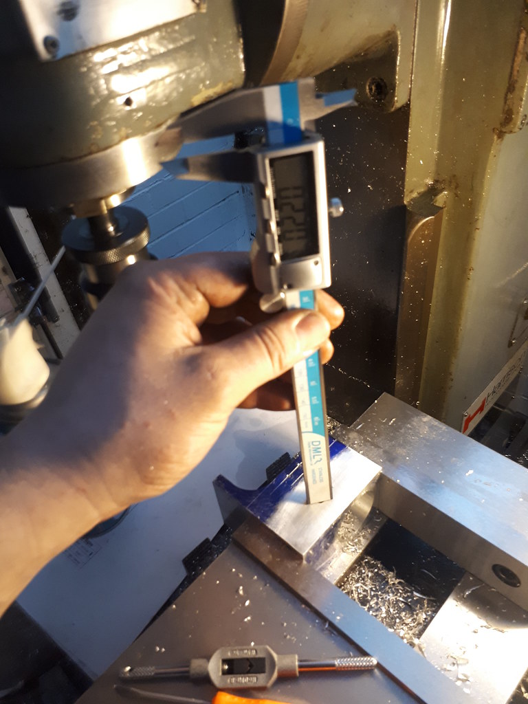
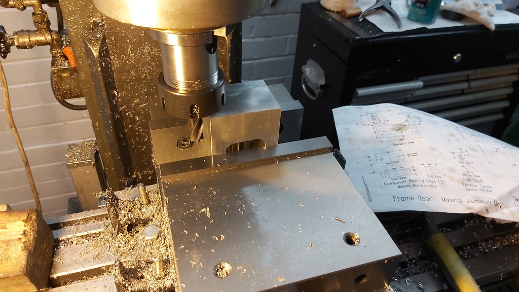
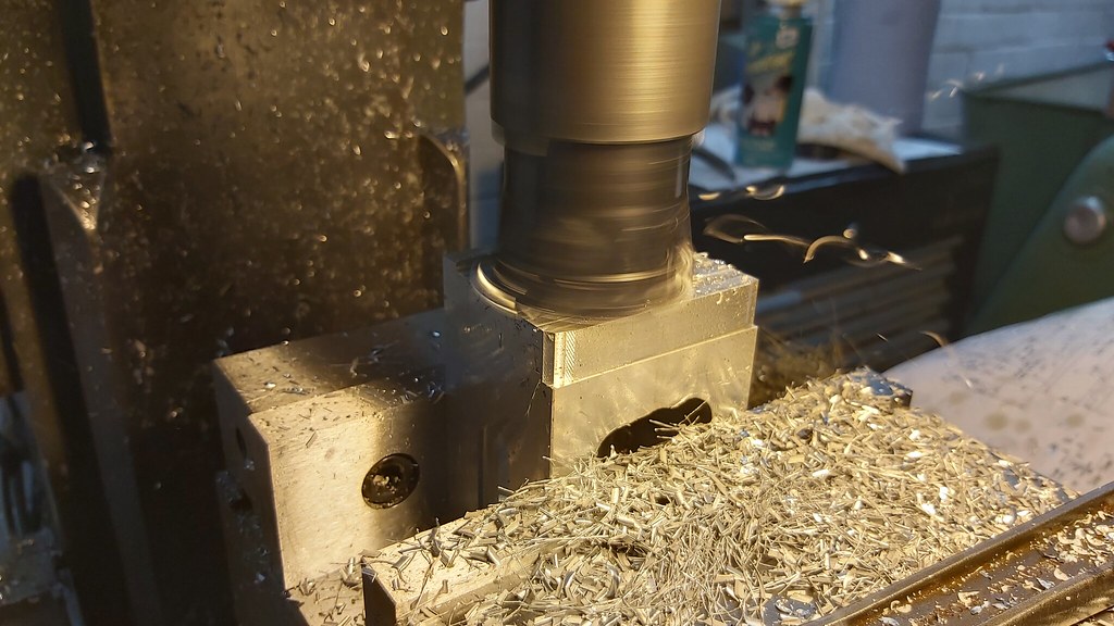
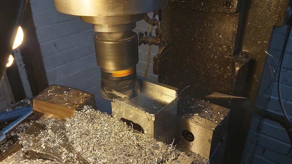
After my first cut, measured and the DRO set so it's simply a case of working toward the 3.0000" mark - double checked on final cut and it came in perfectly. Rotated 90 degrees on the Y axis and did the same. Then rotated 90 degrees along X axis and worked to 2". Came in a hair under at 1.998" I am very surprised at the finish this facemill is giving, and the linear patterns to bother me and most of this will end up in a rubble sack as chips...
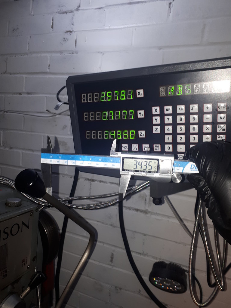

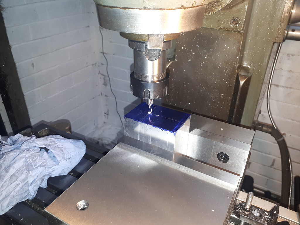
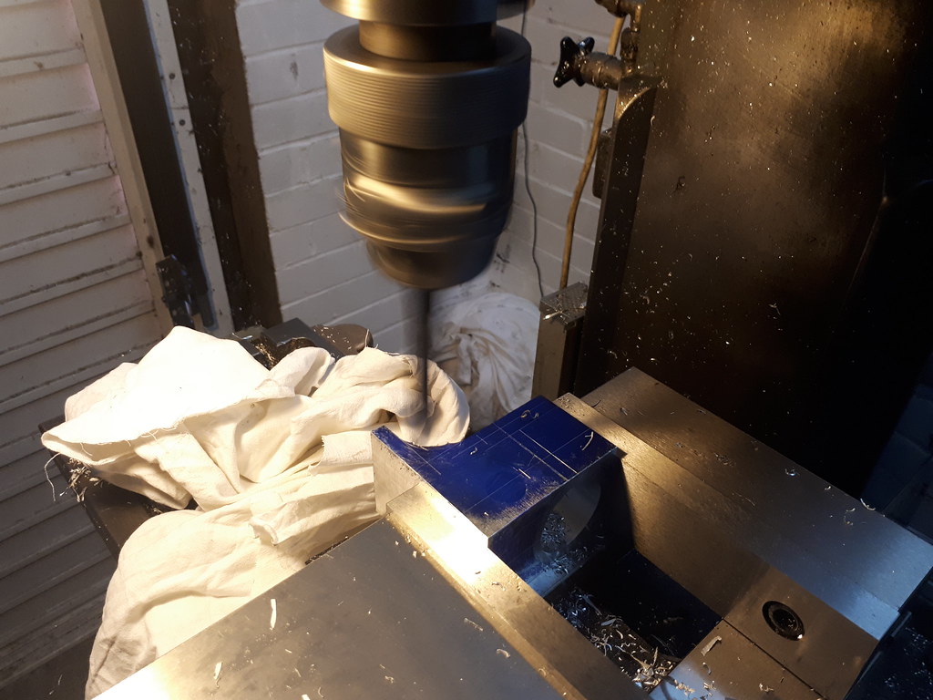
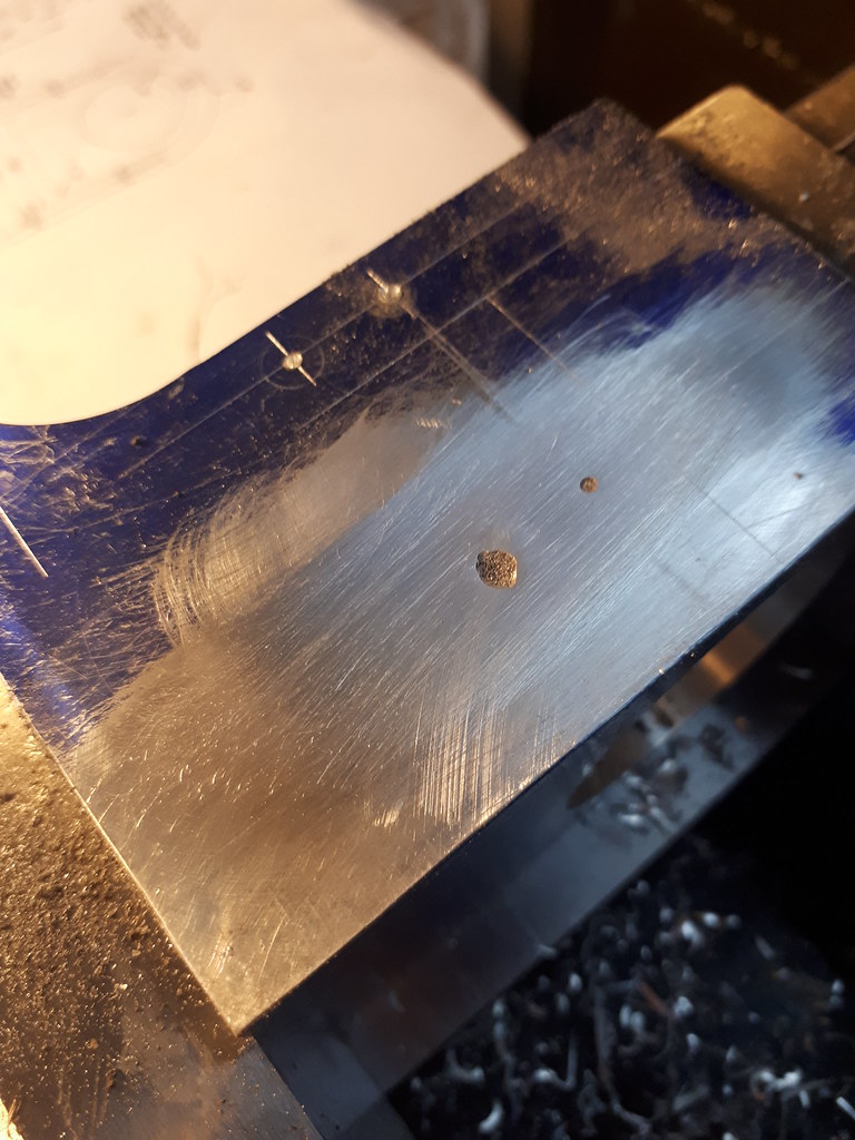
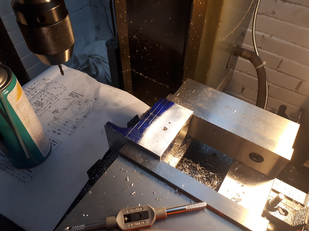
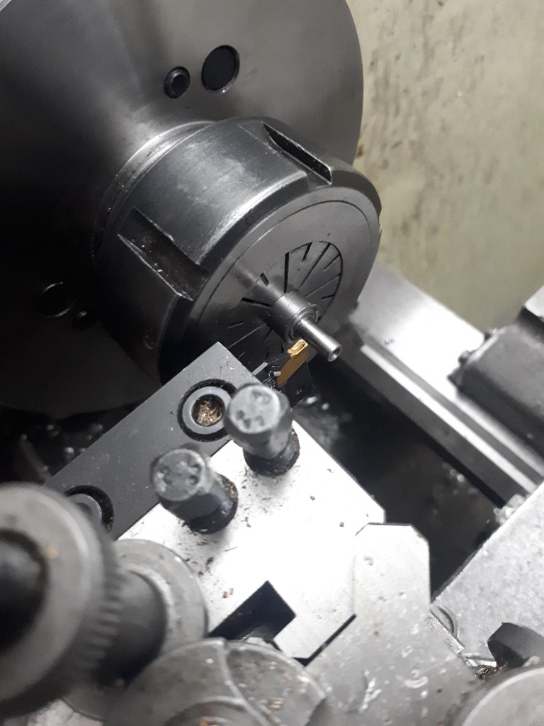
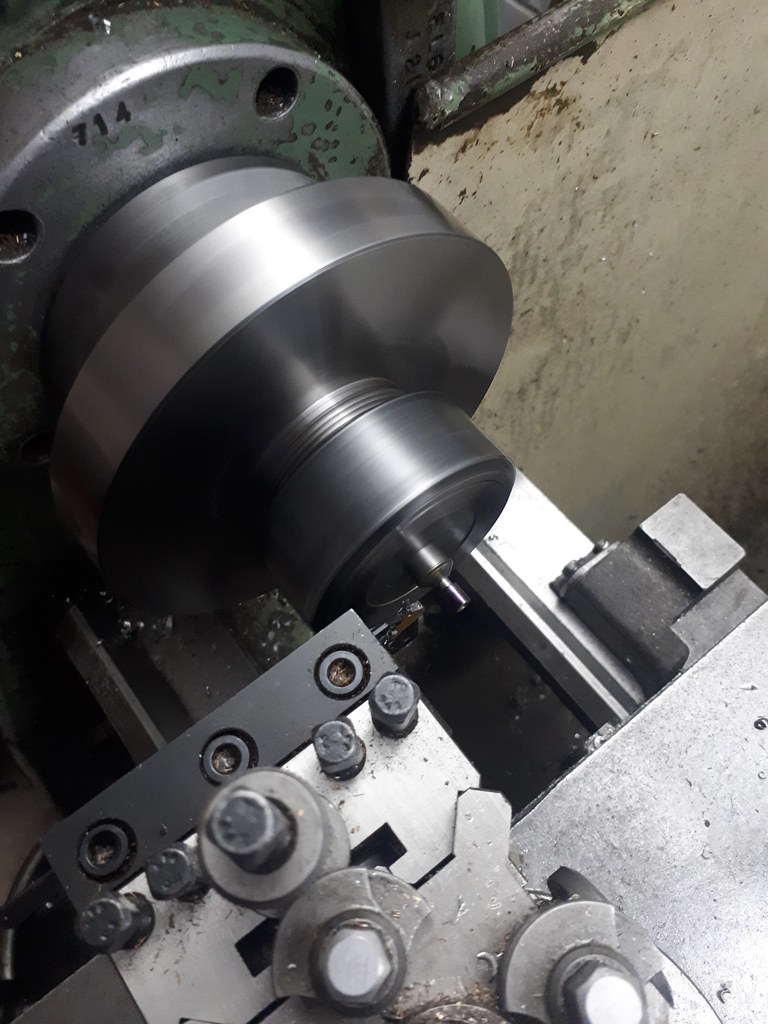
This time marking out the centre point before drilling:


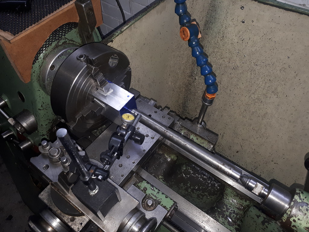
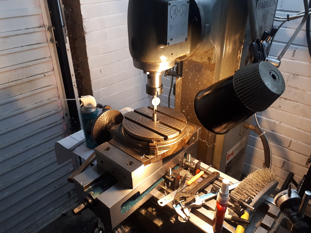
Indicating it in on the 4 jaw - using my "premade" test bar.

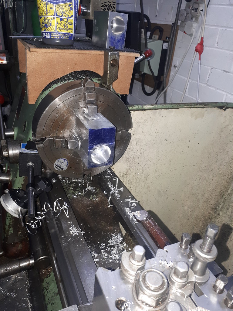
Halleluyah the dimensions are spot on this time. The scrap in the background there...

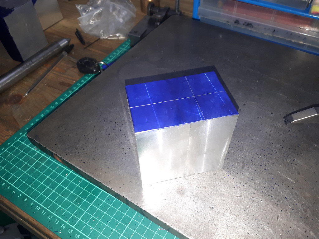
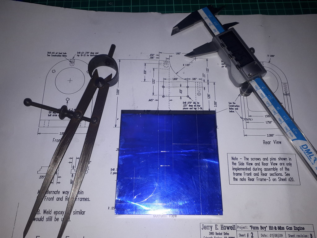
I have to say I am very pleased with this marking out. I just recently got the height gauge for a very reasonable £39 and it looks brand new! Few important lines marked up. And then on wards with more chip making!

Auld ripper.
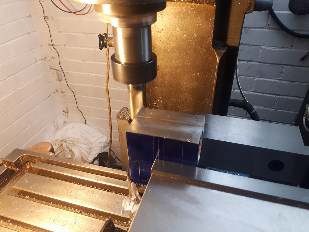


And unfortunately, on that last photograph is exactly where it got left. I had given the battery some abuse almost continually today for around 6 hours. At one point I was drawing around 250A when face milling - the terminals on the cells themselves were cooking! I think we are looking at a good 21hr recharge on it but hopefully be ready for a go on Sunday! And with much less of a tough day I might get more than 6 hours out of them - I couldn't even finish hoovering today!

Thanks again for reading

Earl
 

Just having a look over this post and it goes to show that taking a break and looking over your progress can help reevaluate the method you have planned.

Change of plan with this first cut...

Earl
 
I cheated.
I made the conrod complete with cap and bored big end.
Then had a friend with a wire cutter remove the cap, finished.
The wire cut is only a few thous, just enough to nip up the big end bearing.

Mago
 
I cheated.
I made the conrod complete with cap and bored big end.
Then had a friend with a wire cutter remove the cap, finished.
The wire cut is only a few thous, just enough to nip up the big end bearing.

Mago

Part of me thought about doing something like this too. I kind of wish I had but I don't really have anythign thinner than a 18 thou slitting saw (could have shimmed it though). I have found that any time I try to execute a "better" idea of my own, I find out there is a reason it was designed a certain way! :D

Cheers
Earl
 
Ok so, back home after a quick week away with work. Got pretty much straight back into it.

Spoiler - I had another challenge with the frame front. However I think I have adequately worked around the issue...

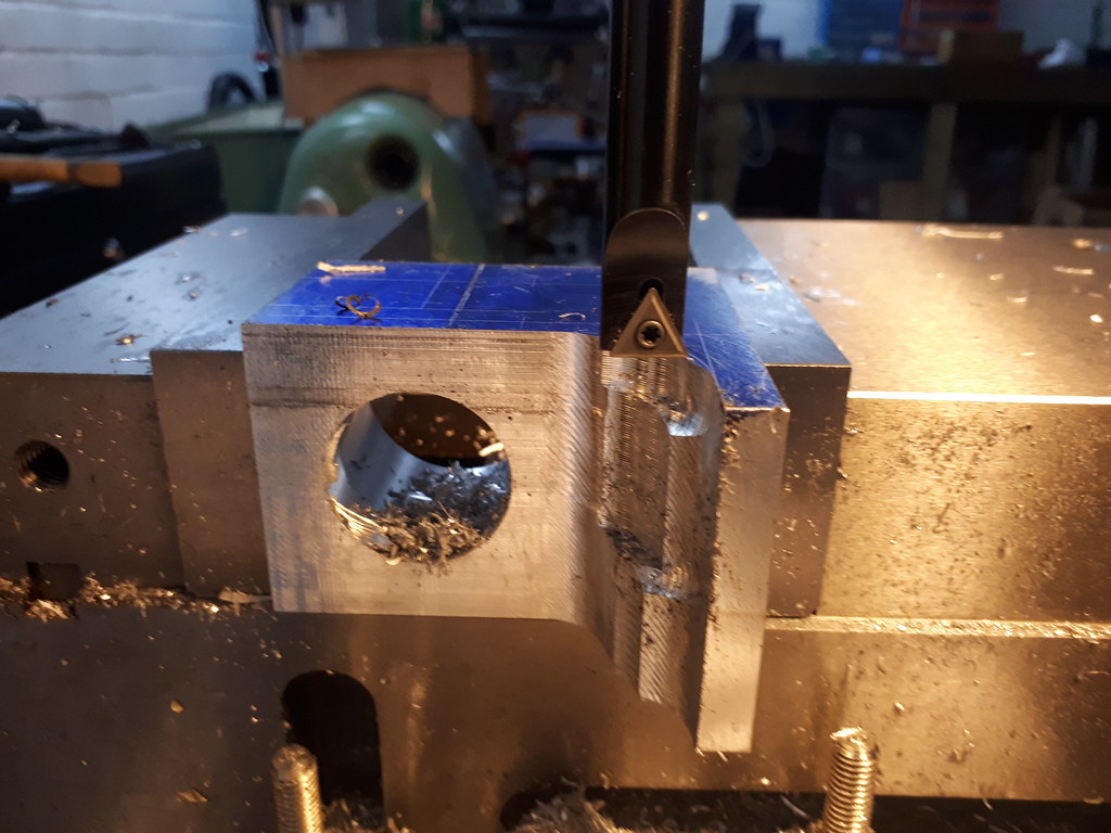
After some thought, and a change of plan, as mentioned earlier. I wanted to remove the next lot of material with the frame laid on its side. This way I could also drill the holes to hold the hit and miss mechanism at the same time.

As far as I know, the quicker way to remove material is saw, then drill. Then the rest.
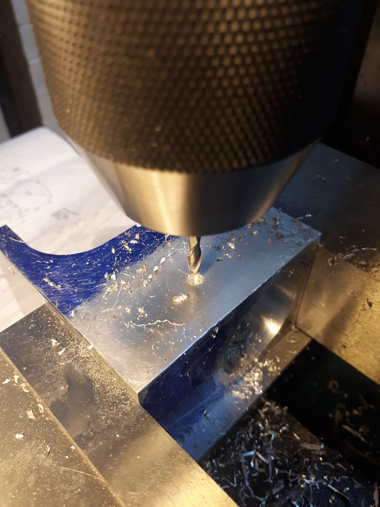
First thing after setting on the work piece and indicating in - some drilling.


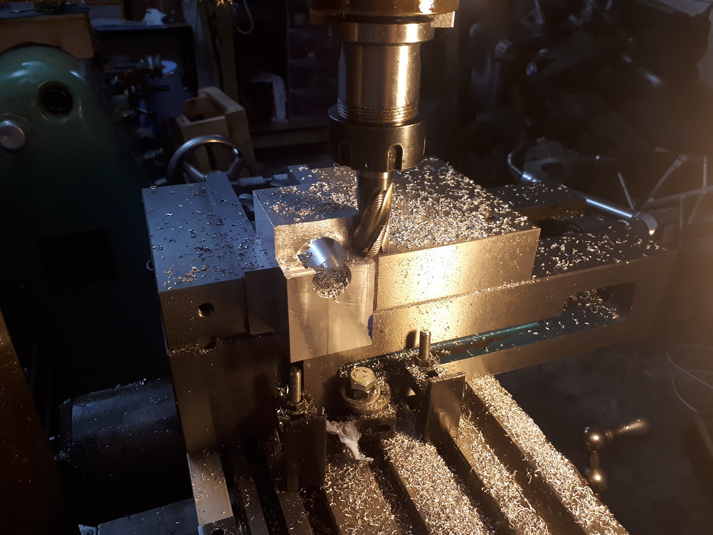
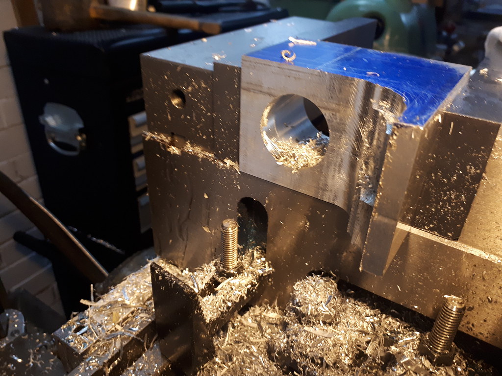
Then some roughing - it really does remove the material fast but gives a whore eh finish. Look closely and you can still see the marked out sizes on the work piece.


Never took any photos of the milling but I replaced the ripper for a normal end mill, I had considerable stick out to give clearance from the tool holder. Unfortunately this resulted in chatter and a very poor surface finish. not to worry, this piece is to look cast and not machined. It actually looks like its just another ripper end mill! I later found that the tool had also bit into to work a bit more than I had hoped. again - not to worry.


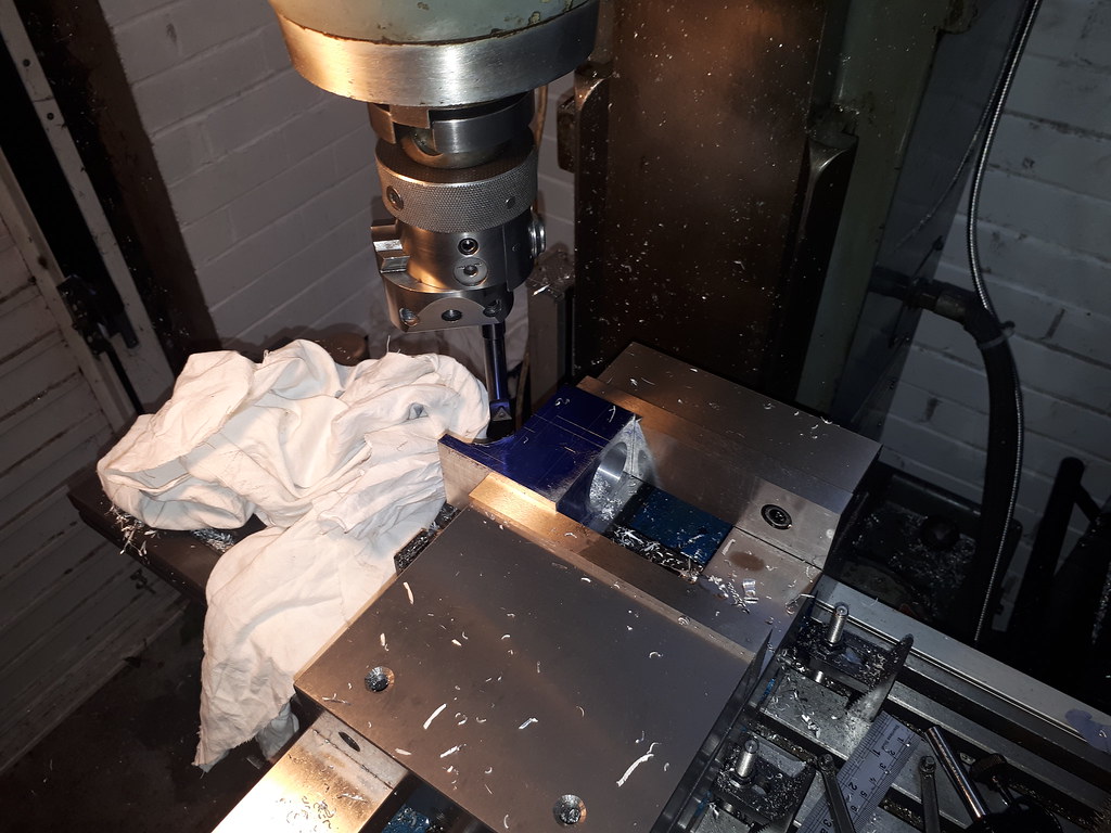
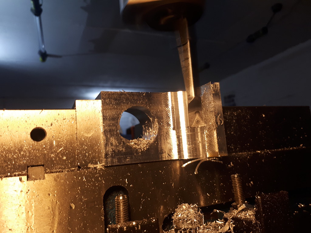
I finally got to use the Enco boring head I got as a bargain! I have to say. The flat on the weldon shank felt backwards relative to the boring head! but I made it work and can grind something in if needs be, It is worth noting this was the first time since owning this mill I have used a boring head. Previously I had an import mill with an MT2 taper and it was really a completely different experience. The thing felt dangerous! whereas this was rock solid! Similar thing between an import lathe and the Chipmaster but not to the same degree.


First cut.


The difference in the surface finish was mega apparent! single pointed cutting tools to work well!


Bang on with the marked out sizes! delighted.


Again the finish was really good. At this point I realised I was a bit too conservative with my end milling up to the tangent of the radius. Just nipped back over it quickly.


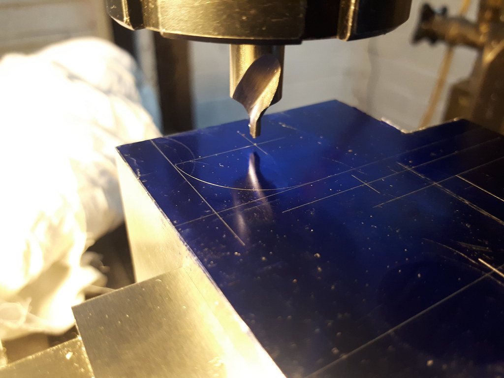
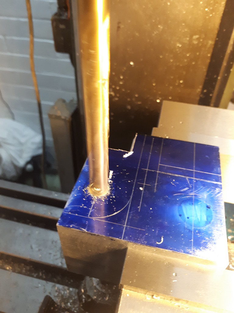
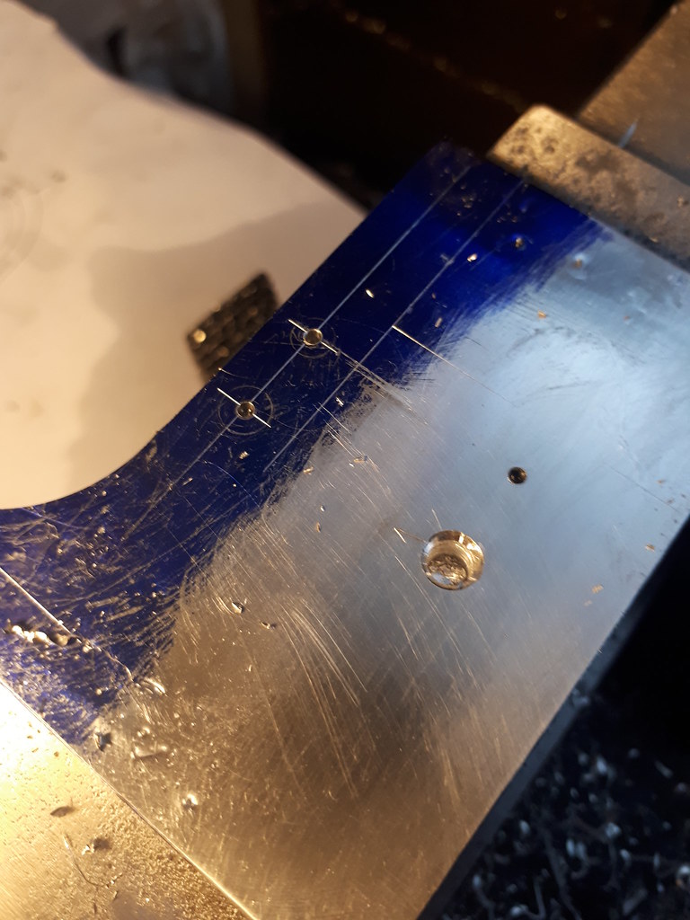
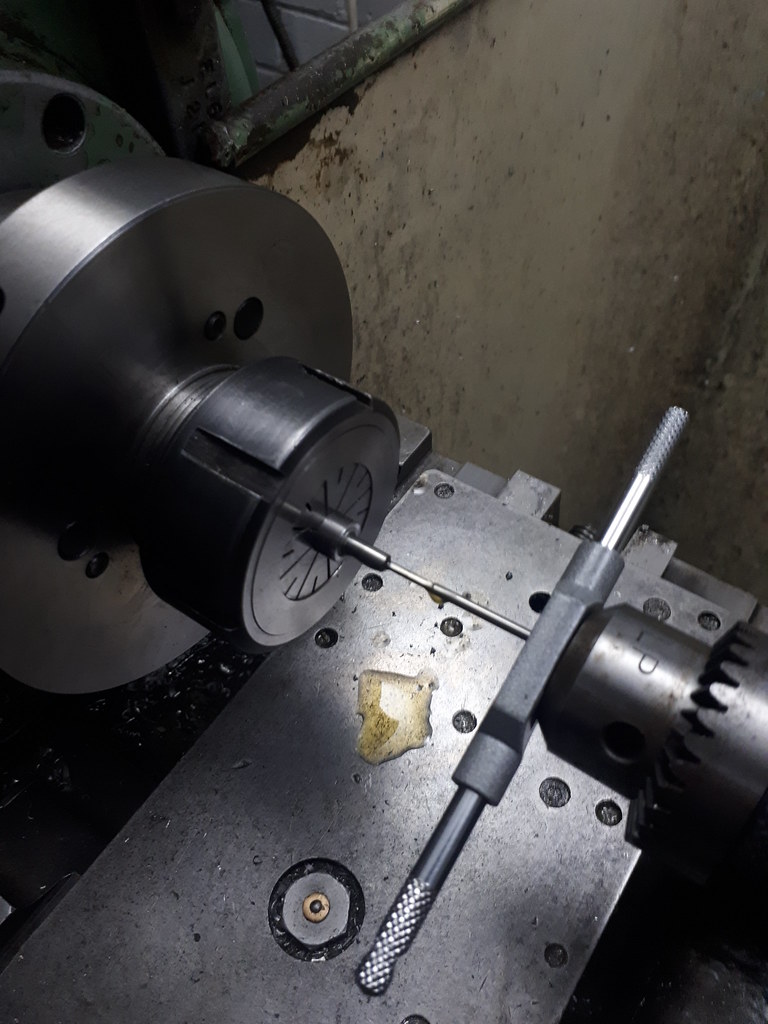
Once I was happy with this, it was time to move onto the small M2 (2-54?) holes for holding the hit and miss mechanism and push rod. Starting with centre drilling to avoid any wander with the tiny 1.6mm drill bits....

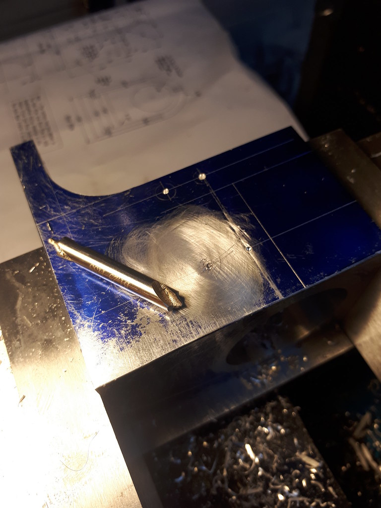
4th hole - disaster strikes! (again). Although this time only indirectly my fault. I wanted to use the smallest possible centre drill for the 1.6mm hole so it was finished to size from the surface down. I have a feeling this came as a freebie set with some Asian machine I bought - annoying as I have a heap of British made bits, but this just happened to be the one I grabbed. the tip snapped into my nice sticky aluminium. After some thought (and swearing) I decided to try picking it out. No good. So then I thought maybe I could break the tip by giving it full welly with a centre dab allowing me to drill out the fragments with the aluminium. This merely drove it deeper. So I thought I would just try drilling it out with a 1.6mm HSS bit - we all know this didn't work.

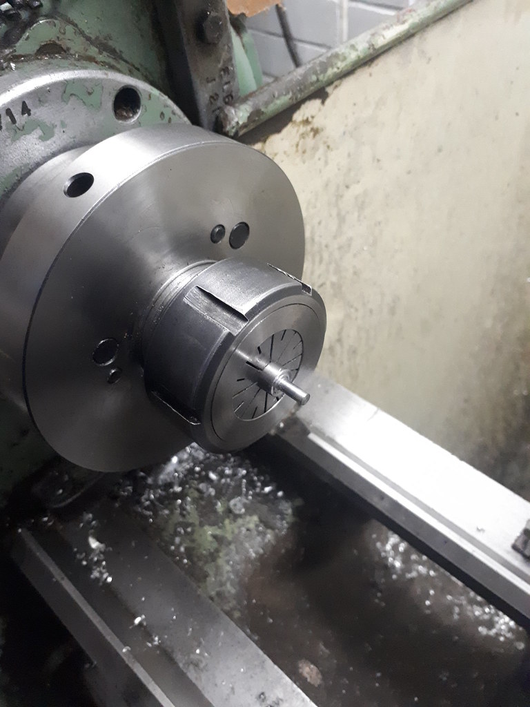
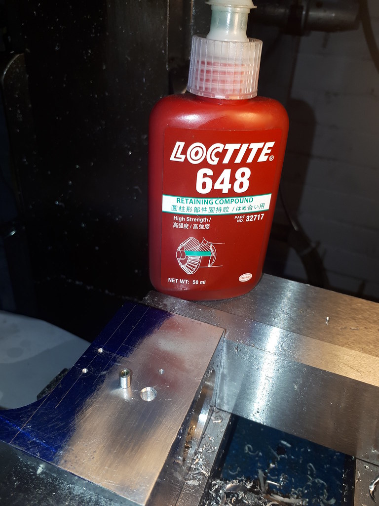
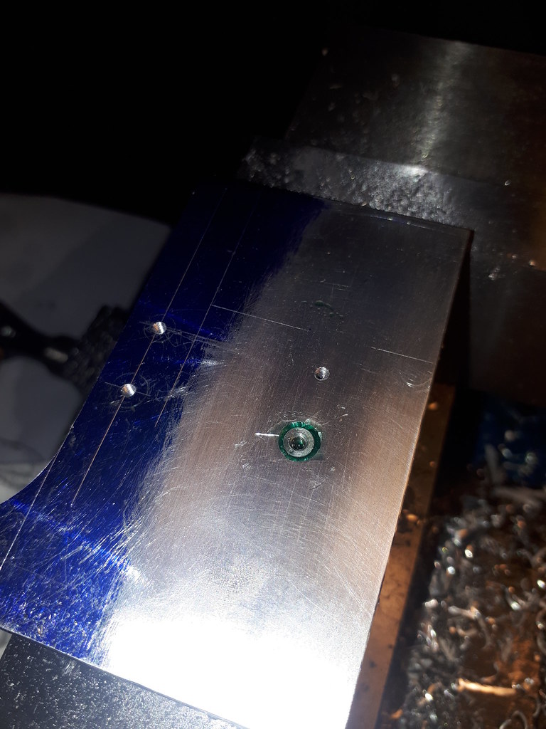
Finally, I had to bite the bullet. It was being removed one way or another and all I had small enough and hard enough was milling cutters. I have a few decent carbide end mills and slot drills - I did toy with the idea of just having 3 bolts and a fake one - probably would have been fine but then the centre drill wins! And that's not good news. A small 4mm piece of silver steel .225" (actually .220) was turned with an M2 hole tapped through. This was loctited (a real verb?) into the frame. I never looked further down the line as to whether this could cause issues but that's many bridges away.


A little counter sinking to aid tapping it in with the toffee hammer.


.220 dialed in.


Decided to colour the piece in purple as it would have been impossible to find even with all the swarf if it fell.


Overall pretty happy with the bodge. It will be filled in sanded and painted anyway so shouldn't be visible.

You can see those left over cutting marks, my final work on the piece was just cleaning it up for the next set of cuts.


Final task, setup the rotary table for tomorrow.


Thanks for reading.
Earl
 
Little bit more progression this time - chipping away, would like to get this piece laid to rest tomorrow!

Onwards!

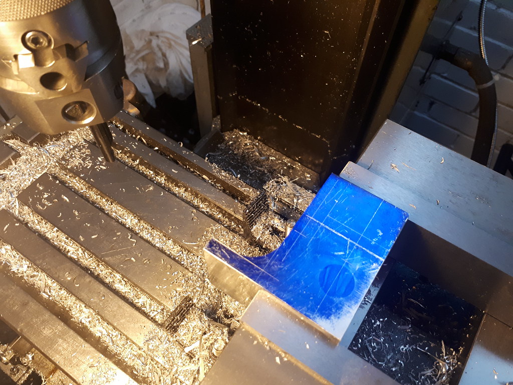
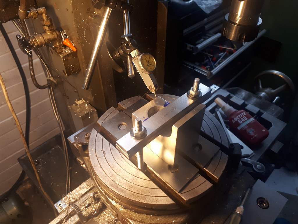
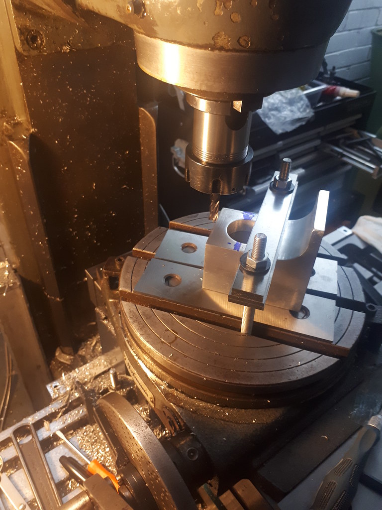
Setting up for cutting the radius:


Award for the most tragic photo:


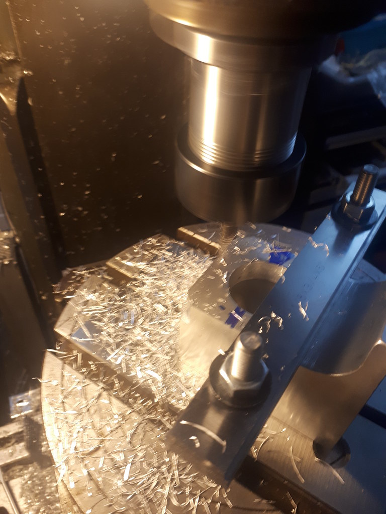
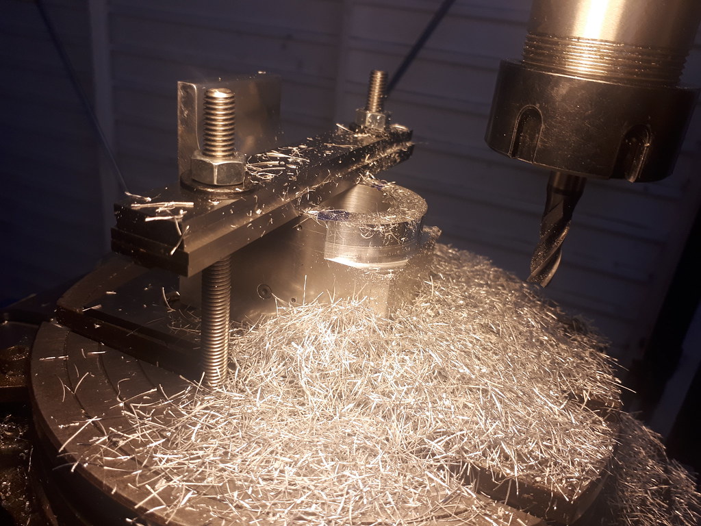
You can see by the shavings I was being incredibly conservative with the depth of cut, moving the table 0.5mm between cuts, as the setup was asking to grab the workpiece! The way the piece was held in also, JUST didn't let me take that last edge off the left hand side. Nothing a bit of wet and dry can't solve.


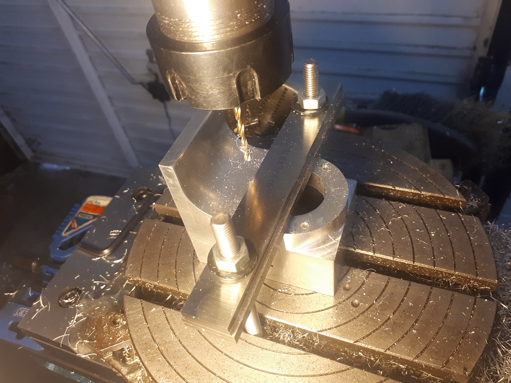
And the holes drilled to take the M3.5 bolts - the eagle eyed would notice I took the work off the table, to realise straight away it was exactly the thing I didn't want to do! Reset the piece and drilled away.


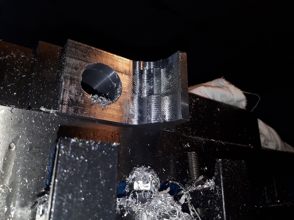
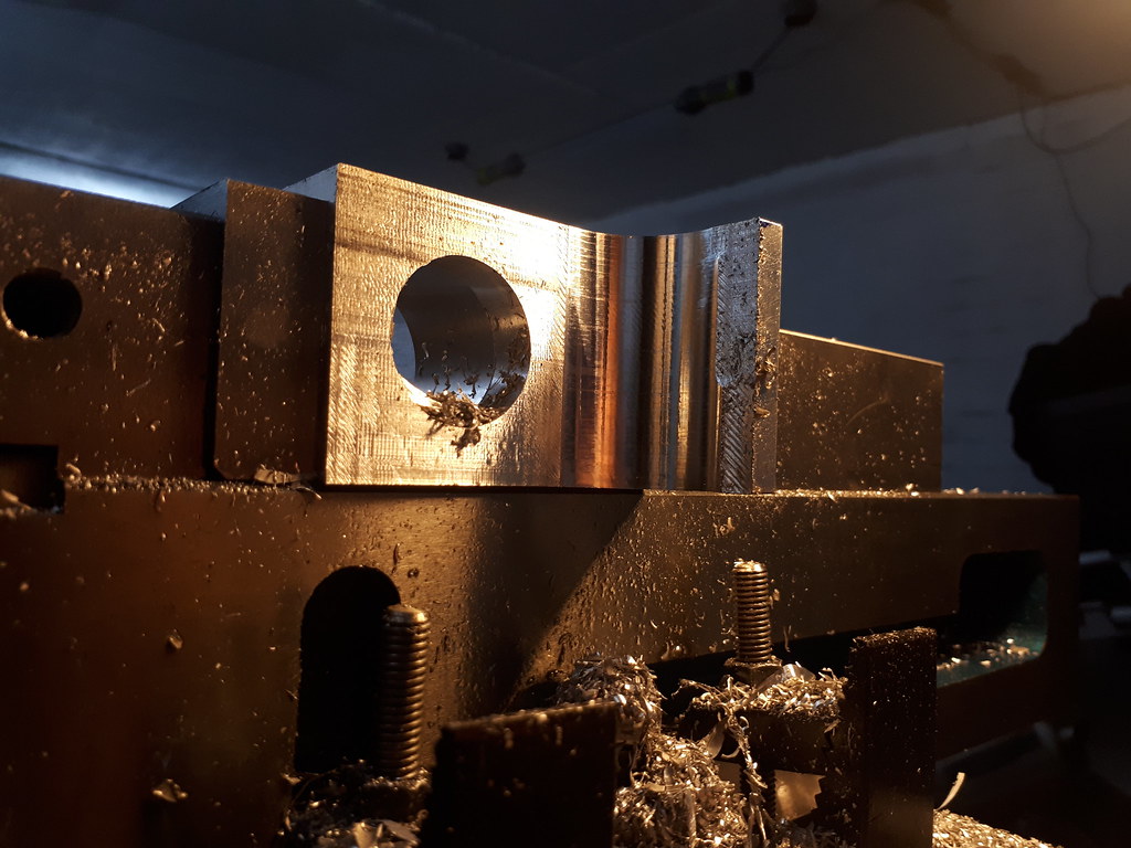
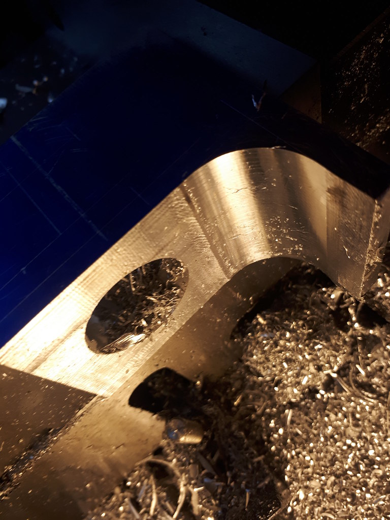
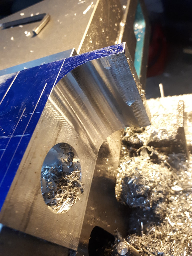
Next, flip the work piece and start carving out the cutaway. You can see this endmill is pretty nasty, so I switched out and cut only the final radius'd edges with this. Even with a brand new carbide slot drill I was still getting a fair bit of chatter, with the surface finish clearly showing it. This I believe is pushing the depth a short end mill can cut to (or stick out) as the collet wasn't fully gripping along its entire length.


Then onto the flanges (?) for joining together the frame pieces.


Setting up the workpiece for the final set of cuts other than a hold at TDC on the radius cut. You can see here were I just couldn't finish the cut on the rotary table earlier.


I just took some material away first with a ripper, then back with the boring head.


Cheers
Earl
 
Quick hit,

Just to finish off the most of this frame front, I do have the base mounting holes to drill, along with the holes for the lubricator but I will get those done later on once I have some other pieces made up and a base decided on.

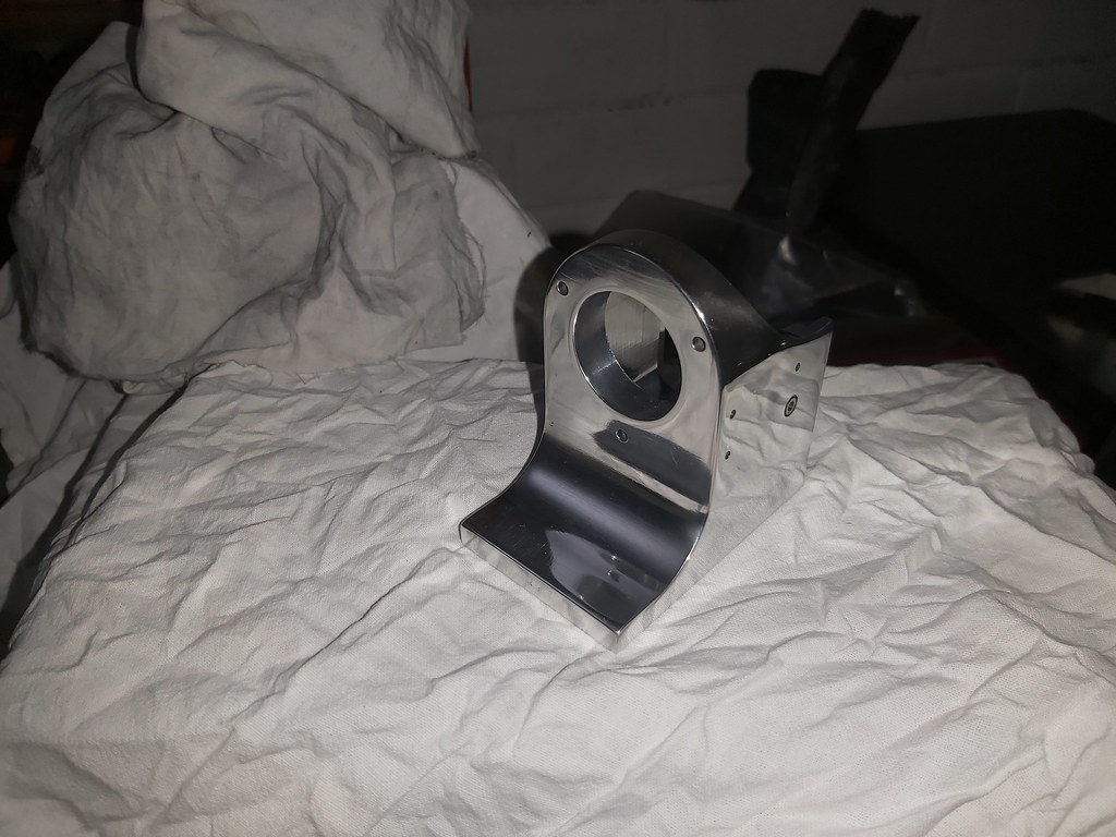
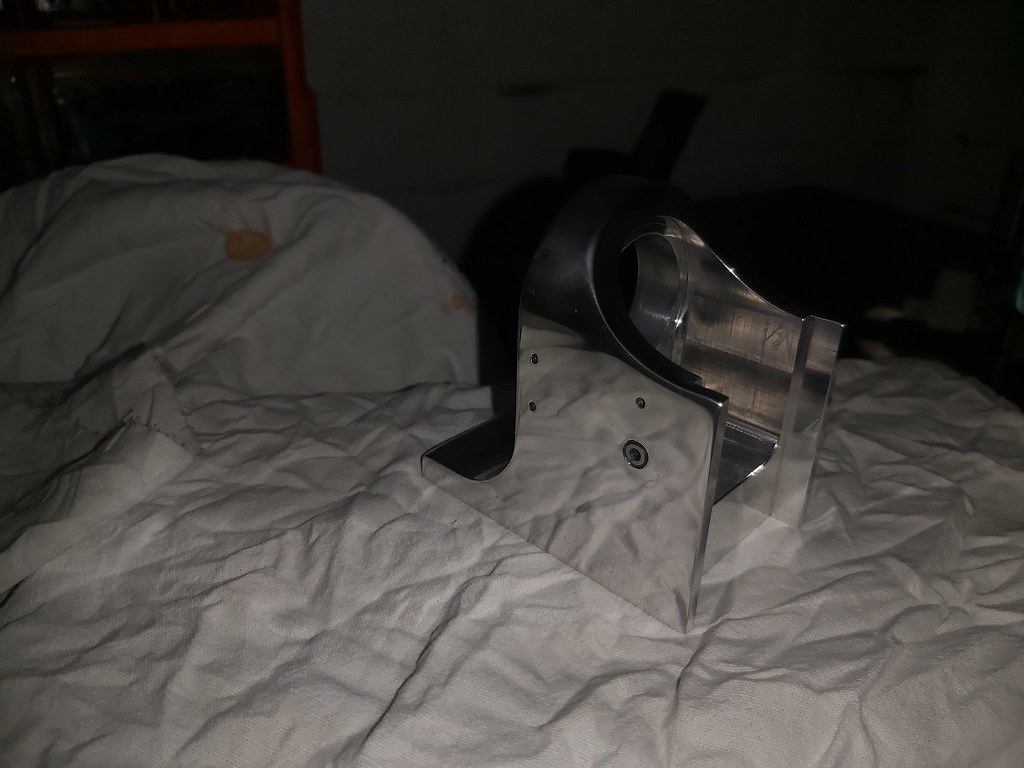
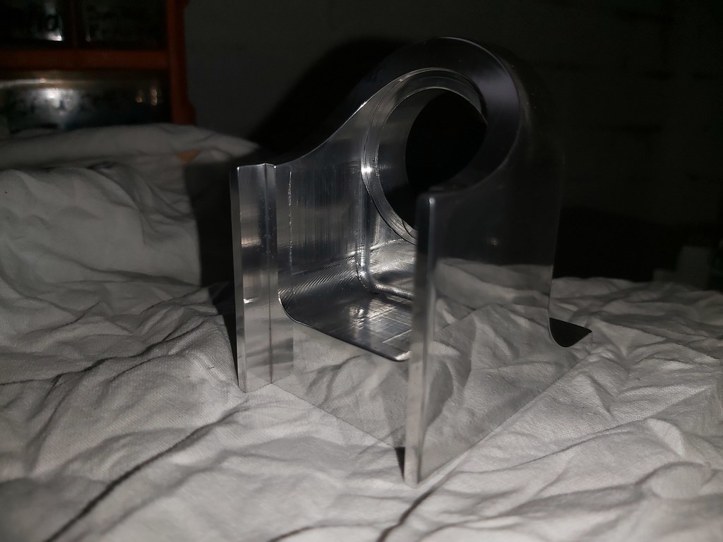
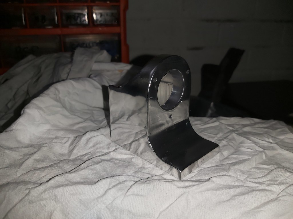
I have to say, my plan is to paint these British racing green, but I could be tempted to polish up and leave as is. Or maybe just paint the hopper or some other combo.

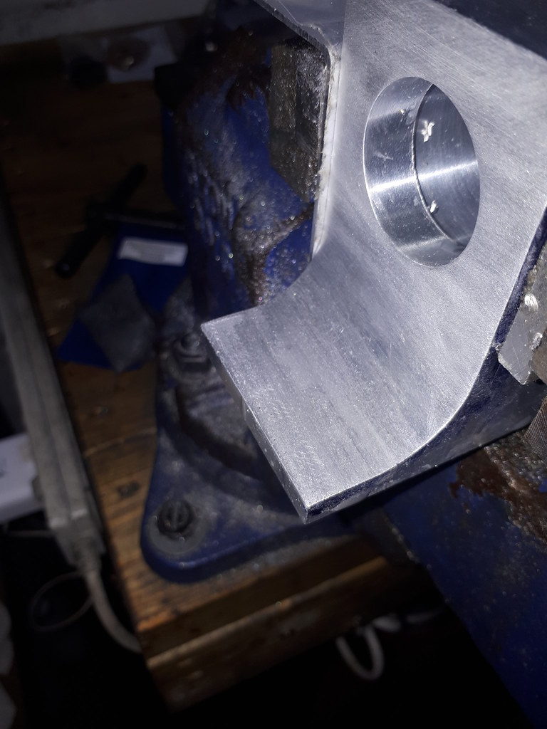
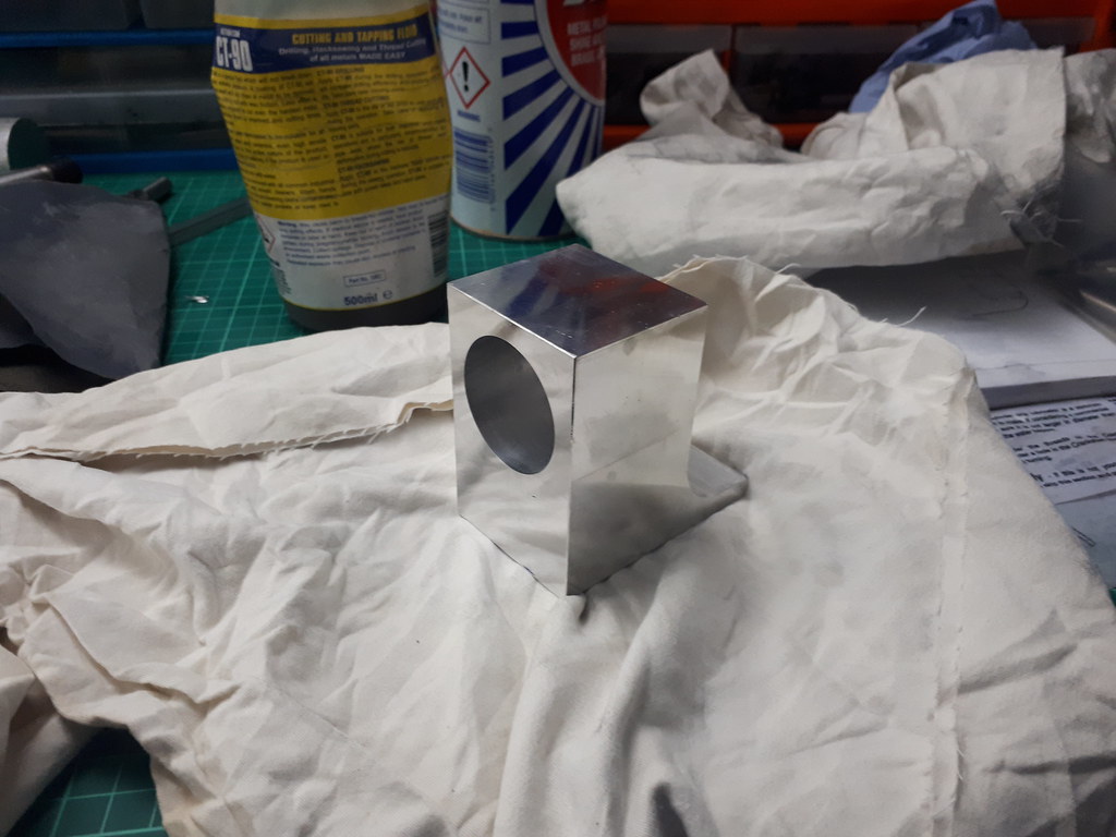
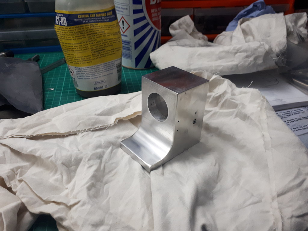
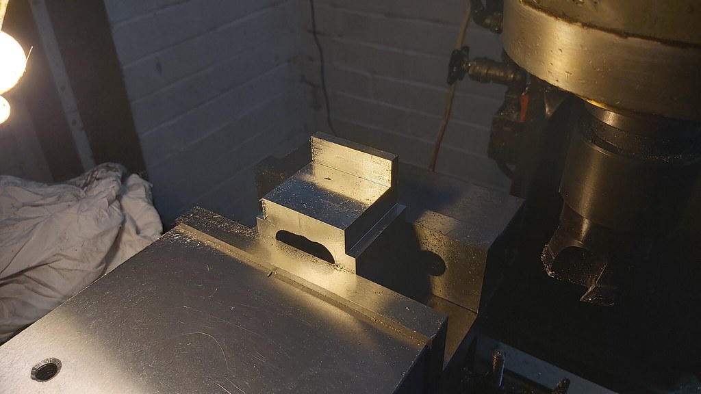
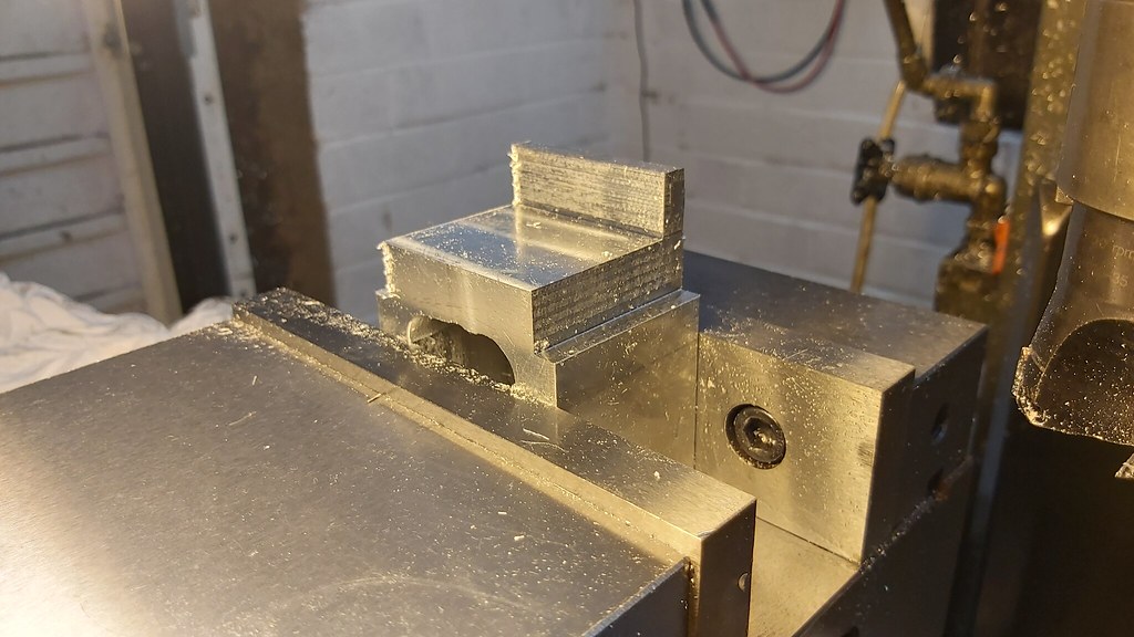
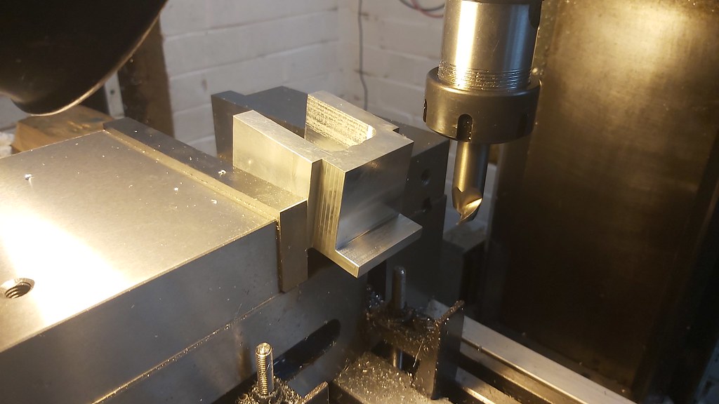
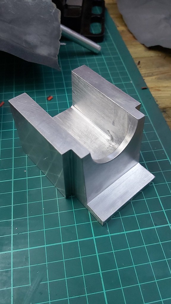
Finished up the boring, was apparent pretty quickly I had milled out the top radius no where near deep enough, but not to worry. Nothing a bit of elbow grease can't solve. I was pretty happy with the finished.


After a bit of filing and wet and dry paper


And some finishing to remove the blemishes.


Next, the frame rear...

Cheers
Earl
 
Grate job Earl! I also considered leave it unpainted. Pity to cover up a good finish. However, when I had the green glossy finish, I was happy with that too. I also considered shrink paint to simulate a rough casting.
Rudy
 
Thanks Rudy, did you need to acid etch primer it first? And can you provide more information on the type of paint you used?

Cheers
Earl
Grate job Earl! I also considered leave it unpainted. Pity to cover up a good finish. However, when I had the green glossy finish, I was happy with that too. I also considered shrink paint to simulate a rough casting.
Rudy
 
Earl, on aluminium you will always need a good etch primer, and the surface must be sanded down and cleaned thoroughly of cause. I have tried the regular non etch types with bad result. I bought a rattle can with primer, so it's not two component as normally used in car paint shops. Guess there are several vendors for this. Not cheap though.. The paint is "ordinary" car paint on rattle can. Don't think the brand is important. The important part is the primer sticking to the aluminium. Any paint will easily stick to any primer, mostly.
Rudy

Tremendous Rudy, thanks for the input!

Cheers again
Earl
 
Well after having a couple of months off enjoying the sun I got the itch and decided to continue with the build. I broke myself in gently enough. Not going to go into too much detail as not a great deal has been done but probably put another 6-8 hours in and the frame rear is starting to take shape.

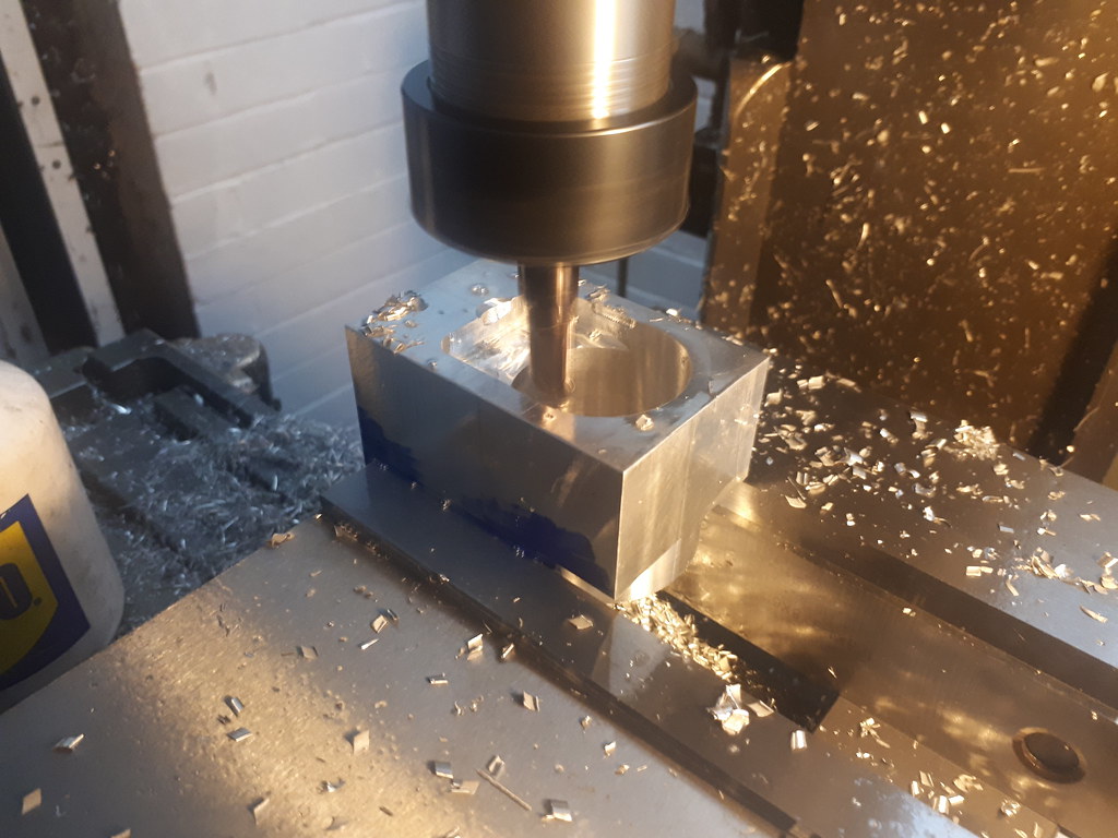
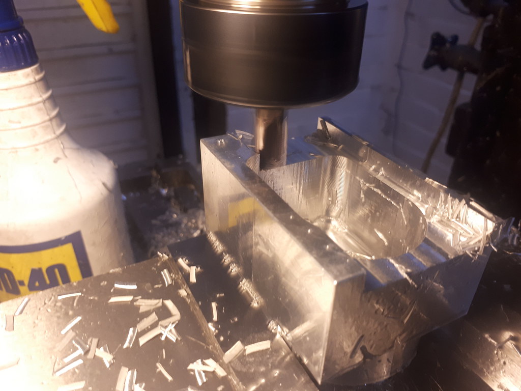
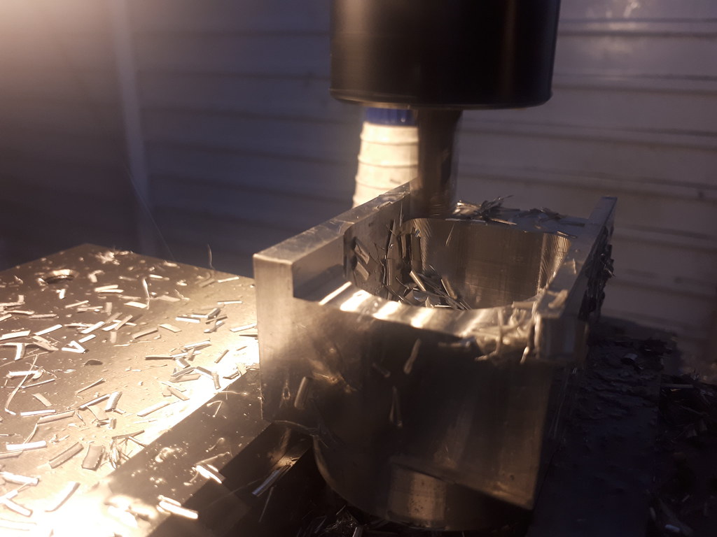
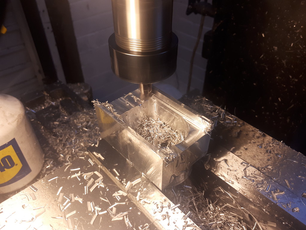
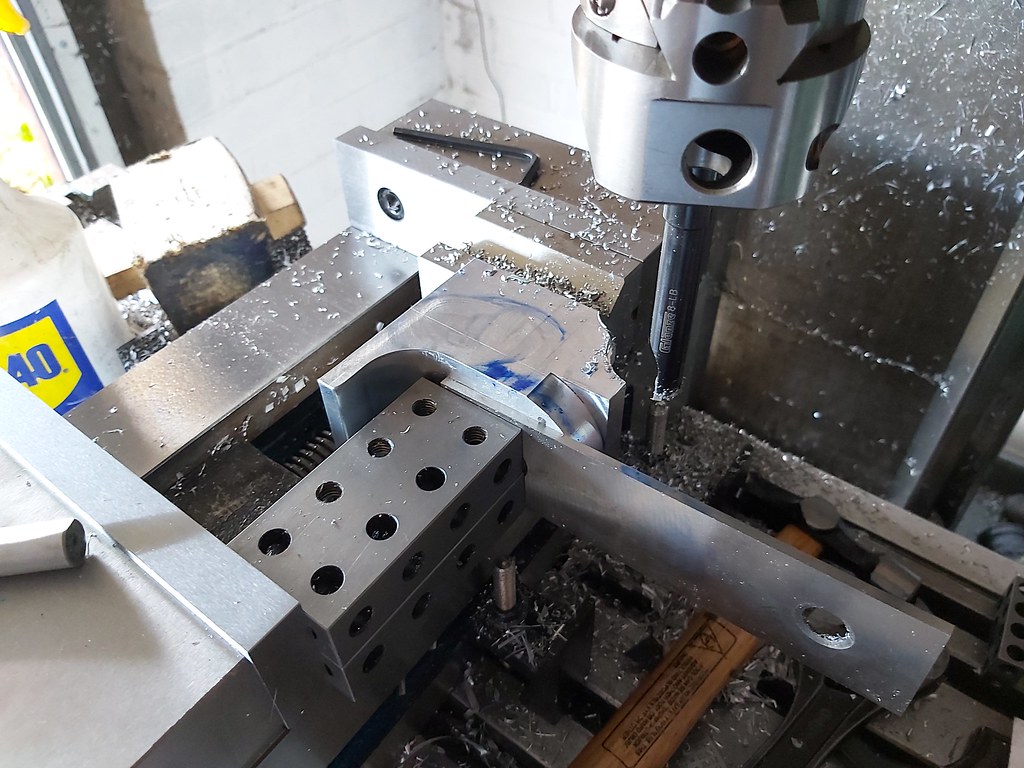
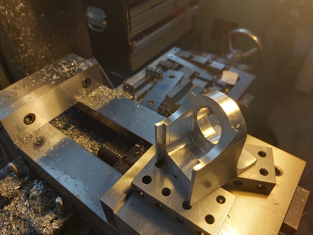
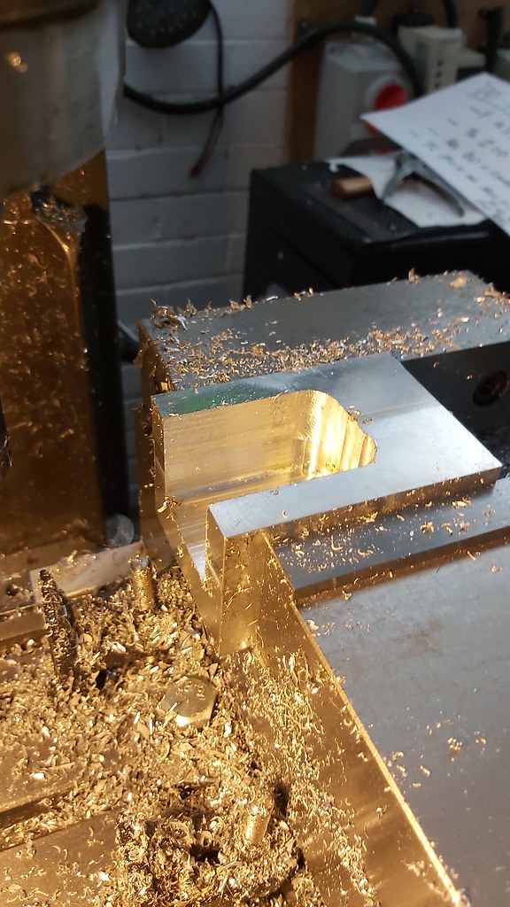
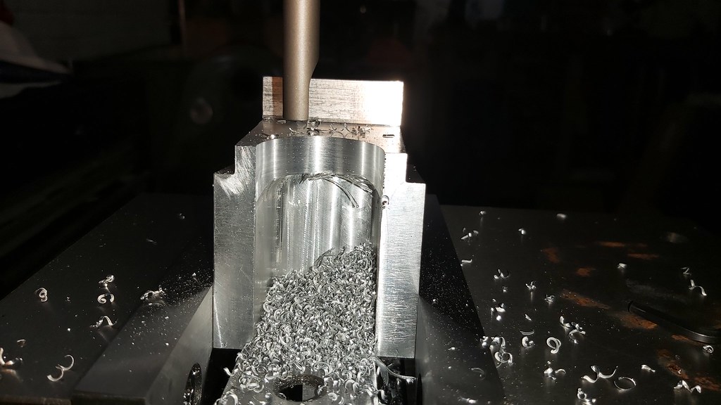
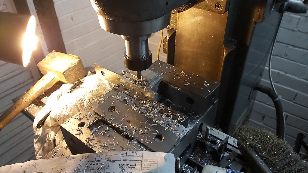
Hogged out the majority of the material:


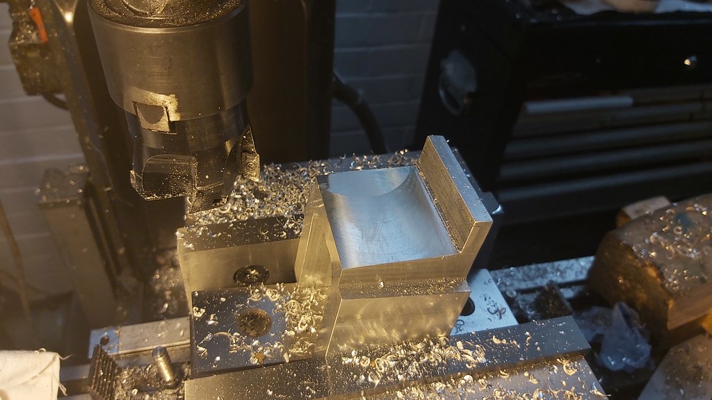
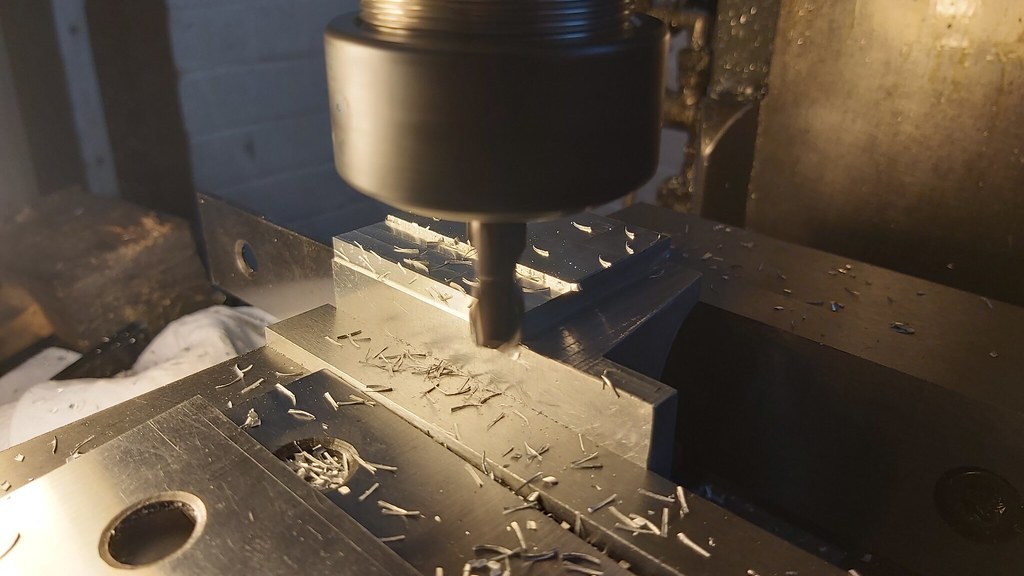
Rotated to workpiece to continue the material removal. At first I had planned to use and end mill, but decided the facemill was going to be much faster:


And taking down the overall width to 2" up to the con rod bearing cap area. The facemill wasn't really the right tool but I left a couple of thou on to clean up the surface with wet and dry, and this size isn't critical:


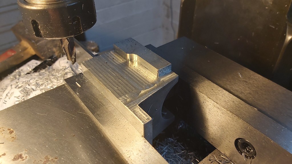
You can see the quality of the first cutout (the area held in the vise) but this is cut well undersize with a finish cut to be taken on the 8 degree design slope.
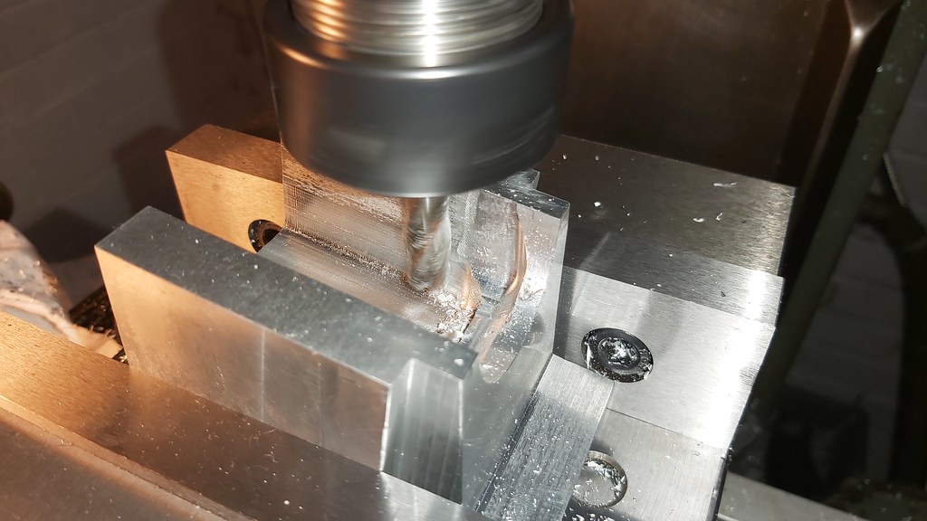

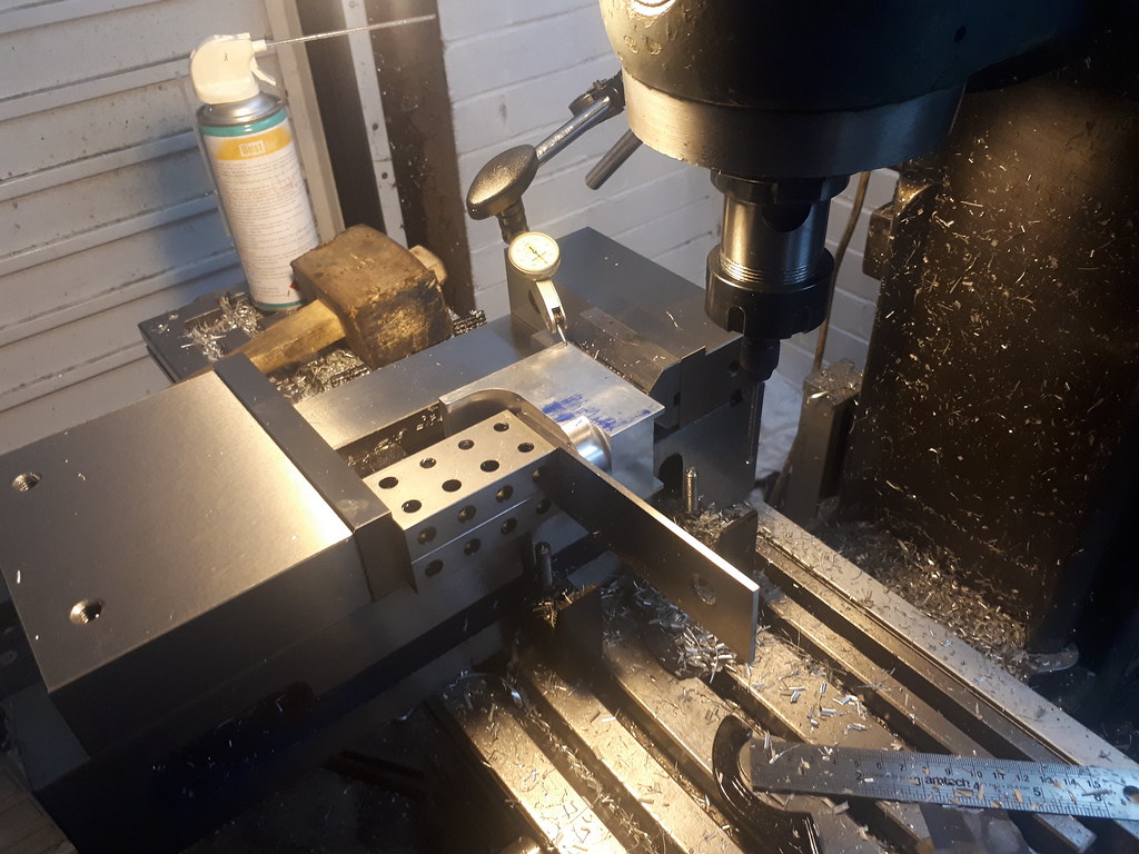
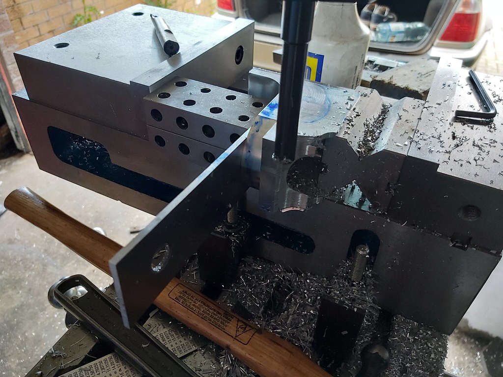
I initially set up the work piece on the angle blocks to cut both sides of the 8 degree slope at the same time to keep things equal. But changed my mind in the end and went with the facemill. I should be able to quite easily rotate the work piece to cut the internal angle, setting it up on the angle blocks again and indicating the surface I have cut during this setup.


You can see the setup isn't perfect but that imperfection can't be felt and will wet and dry out quite easily:


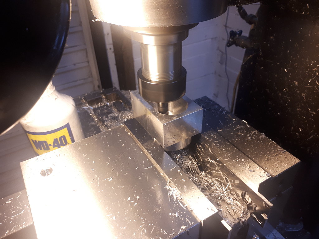
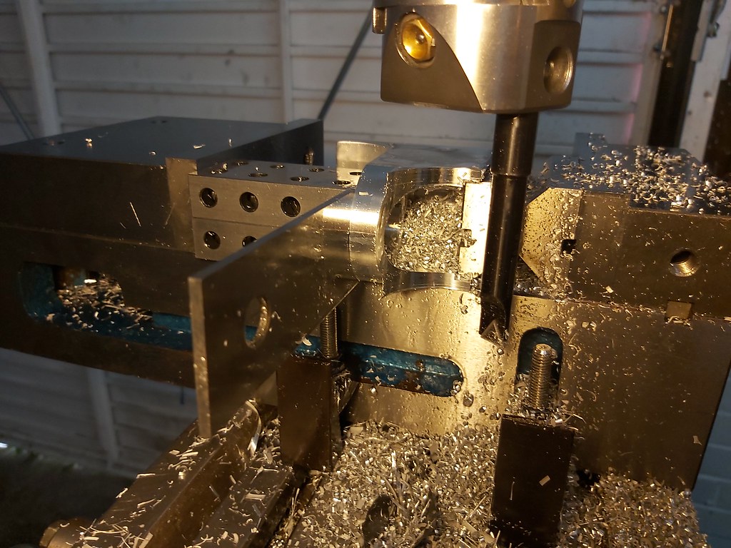
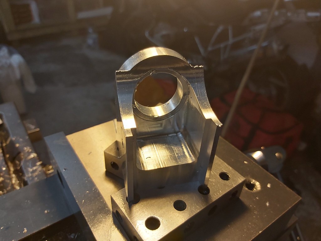
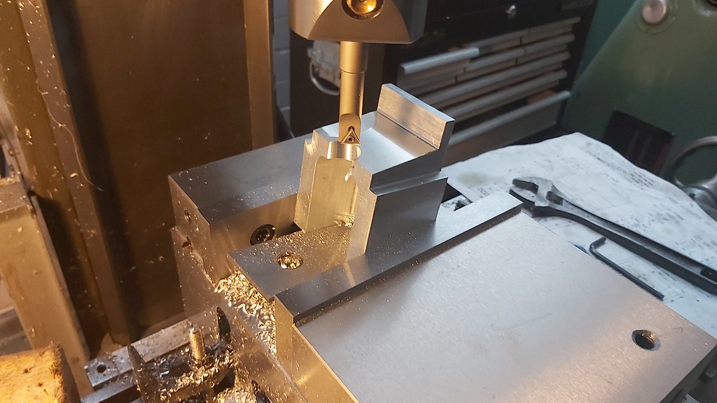
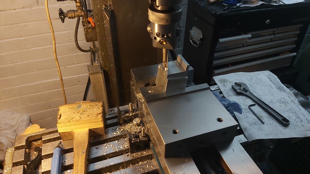
Using the same setup to start boring out the 1.5" dia cutout, that from what I can see also follows the 8 degree angle.


That's it for now,

Thanks for reading.
Earl
 
Been on holiday between my rotation so only spent 3 days at home in the last 6 weeks prior to Thursday there.

Just a wee update to stop the thread stagnating, no huge progression. Got around 3 hours on it today as I was busy tidying up and improving the lighting around the garage. There's always wee jobs to do in between the wee jobs in between the wee projects of course.

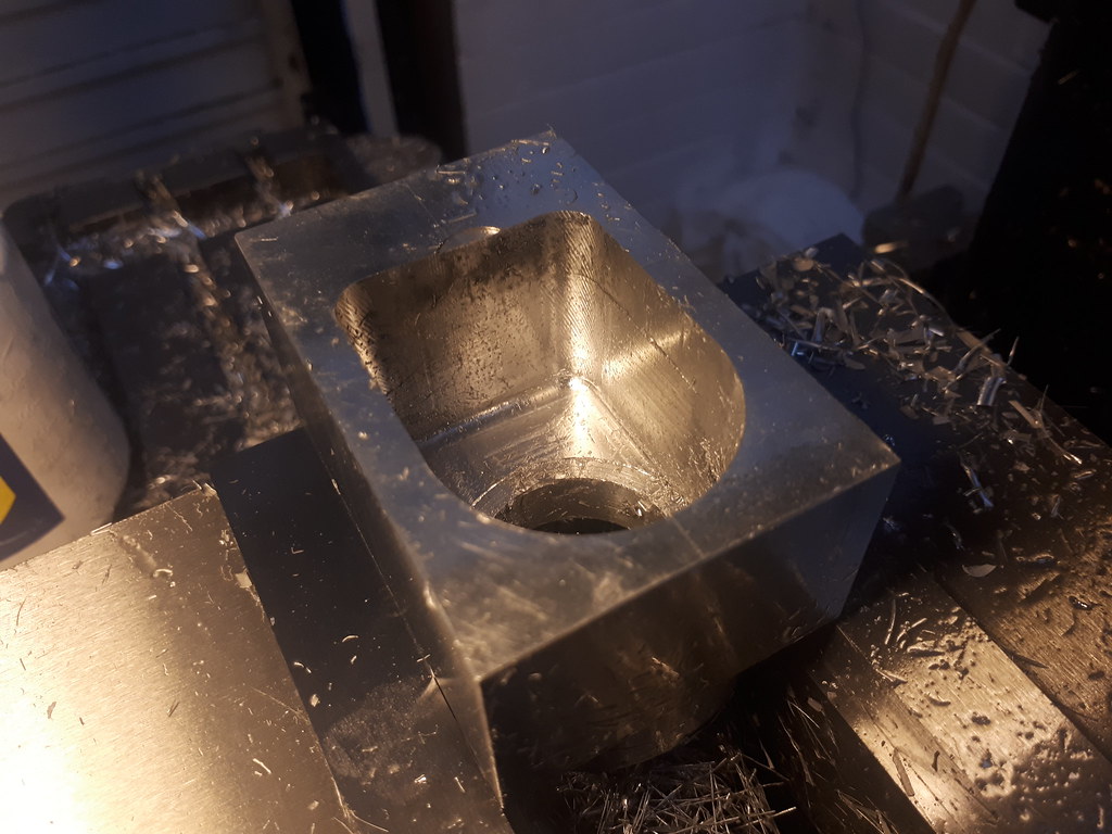
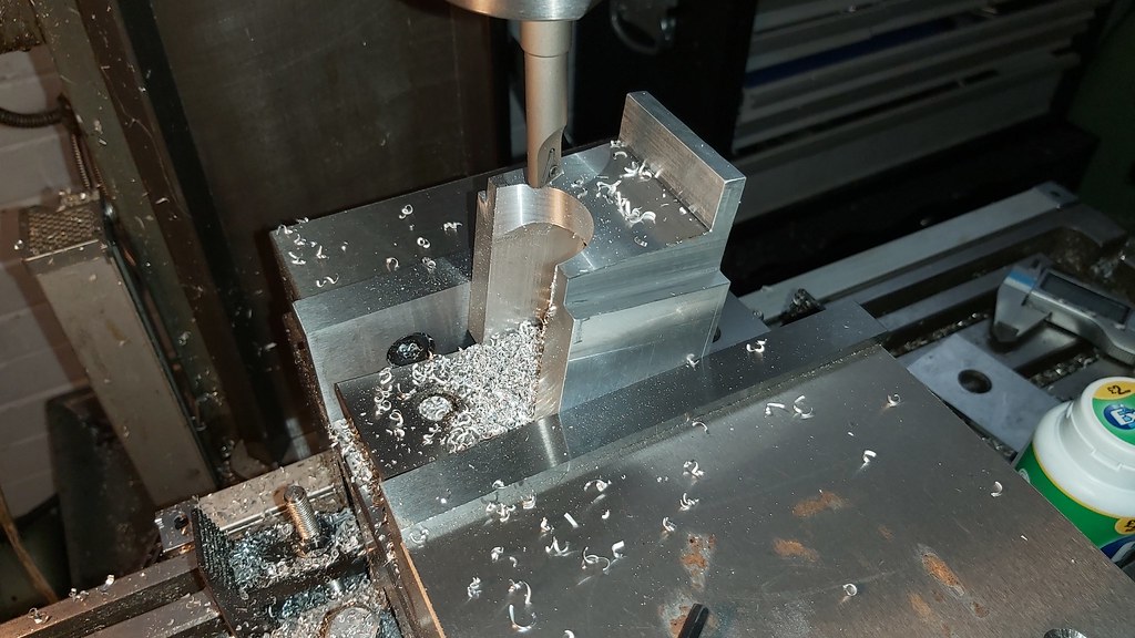
Continued just where I left off, finishing off boring to size. It become very apparent just how much breathing room I had given myself when first hogging out the large cavity/void are (or whatever it could be called)


Work piece turned and again supported on the angle blocks for finishing off cutting out the opened area.


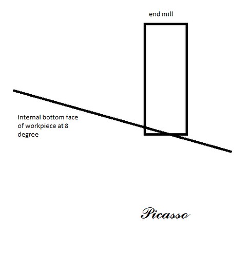
As this was now sat at 8 degrees, and not having 3 arms to be able to ramp this properly down I just cut it close enough. The original material removal was done with the piece sat parallel to the table, where as now tilted up I ran the risk of cutting into that level plane at the bottom of the cut out - knowing there would be a better way to display this rather than describe I called on a friend of mine for some artistic assistance.


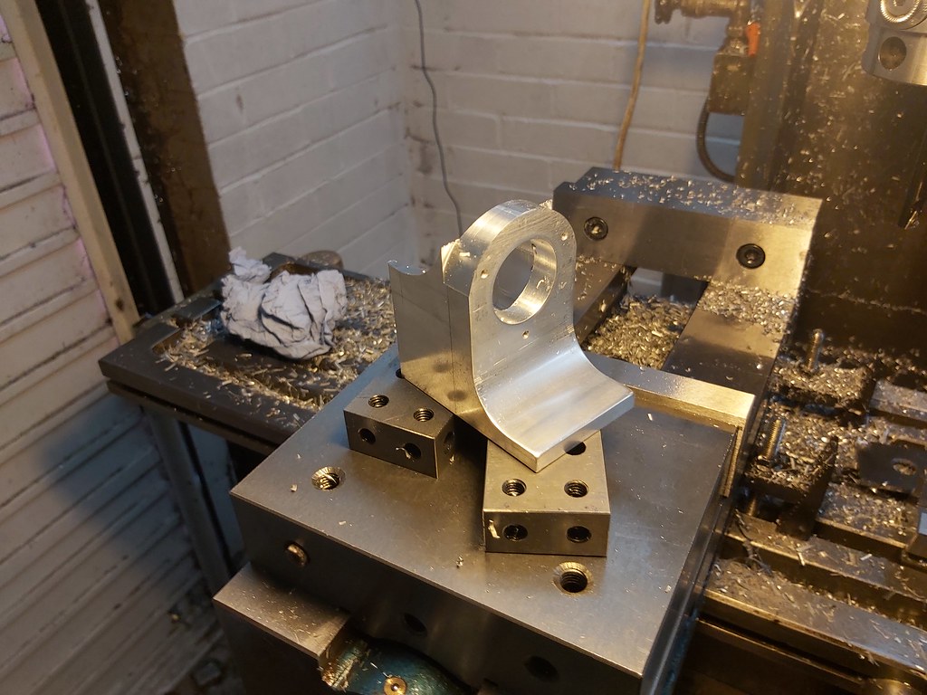
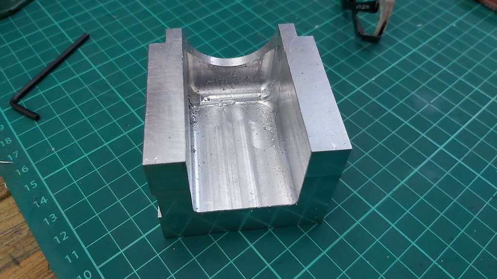
I just did what I could knowing that this area was not critical, and probably wouldn't be seen in great detail either - turned out good enough.


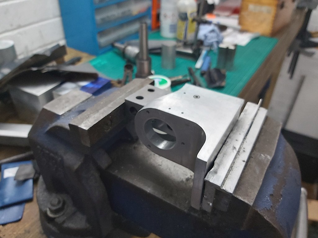
Tidied it up with the Dremel and some wet and dry. The piece isn't finished yet so I didn't put a heap of time into it knowing it will be getting put back to the mill for more machining.


Back to the mill for the next cutting operation, which is where I finished up for the day.


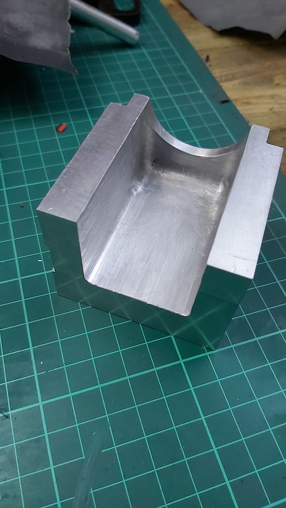
Not the best finish to look at but it feels smooth and this will be wet and dried back either for painting or polishing.

Thanks for reading, hopefully get a bit more worked through next up date but I have some projects for work I want to get done - which was actually the reason I carried on with this, to get it bored and out the vice.

Earl
 
Not sure how but I have left a [\URL] in somewhere, cant see where but never mind.
 
Earl--I see that you are polishing the aluminum parts. That is a good thing if you plan on not painting the parts. The wax used while polishing will keep those parts from oxidizing almost forever. Not so good though if you plan on painting the parts. Anything polished will definitely need to be washed thoroughly with paint thinner to get rid of the wax, then scuff sanded with 1000 grit paper to make the paint stay on. I have thirty some model engines setting around my office, and only one of them is painted.--and it is painted with a rattle can of blue automotive paint with no primer.---Brian
 
Thanks for the advice Brian,

If I am so paint these, I will be heavily priming them with acid etch. I will take your advice on board when considering the surface preparation. I am guessing painting aluminium can be so much hassle that leaving the parts as bare metal is easier but still looks good.

Cheers again,

Earl
 
Earl--I was always taught that to properly adhere to aluminum, paint needed a good zinc chromate primer laid down first. That being said, I've never had a problem with spray on enamel from my local hardware store. A lot of the reason that I don't paint my engines is tied into the way I build them. I assemble my engines piece by piece as I build the pieces. By the time the last piece is finished and assembled, I never have the urge to take everything apart to paint it properly.
 
It has been a year since the last posting. I am curious to know what the status of the project is as I am in the middle of my own effort. One thing I will mention is Mr. Howell talks about using acetone as a fuel. If you want to do that, don't paint the frame.
 

Latest posts

Back
Top