Best approch for machining a small flywheel?

Home Model Engine Machinist Forum

Help Support Home Model Engine Machinist Forum:

This site may earn a commission from merchant affiliate links, including eBay, Amazon, and others.
Hauk,

The simple way with a 4-jaw chuck is to use 2 keys. This way you can adjust the jaw pairs to get the work to run true. I had to make a special long key for my mini lathe to clear the motor.

I know this has been posted on the forum several times but it really is a lot faster than a single key because the work is always clamped and you split the indicator reading with each set of jaws.

Dan
 
Hauk said:
Yep, a 4-jaw chuck would be nice. But how easy is it to clock up a part in a 4-jaw? Is it far easier than getting a part to run true in a 3 jaw?

It is when your 3 jaw refuses to cooperate - which is going to be the case for really accurate work.

I only ever use the three jaw for repetative work where the OD is going to be turned in any case so concentricity (within reason) is moot.

A three jaw is quicker - no doubt about that - but I can MkI eyball a 4 jaw to about 0.005" TIR just using my tool tip as a reference in about 40 seconds, dial gauge to 0.001" in about 90 seconds and better than that 2-3 minutes.

Like Steamer says it is a skill you should aquire.

Regards,
Ken
 
After eyeballing, ( mostly by using the machined rings on the chuck face and looking where the item sits in the jaws), my way with a 4 jaw is to use a hand held piece of sharpened chalk. You can rest it on a tool holder or simply offer it to the workpiece directly. You can get pretty close with chalk and it won't damage your workpiece, or you, in the event of a whoopsee. After this, if needs be, out comes the clock gauge, fitted with a simple bracket for the toolpost.

Chalk is especially good for black, (unmachined), metal and of course you have a choice of colours to suit your mood ;D

Hope this helps

Best Regards
Bob
 
Hauk said:
After a long break from any serious machining due to an epic crash (in my book at least) I am ready to have a new go at the job that ended so badly.

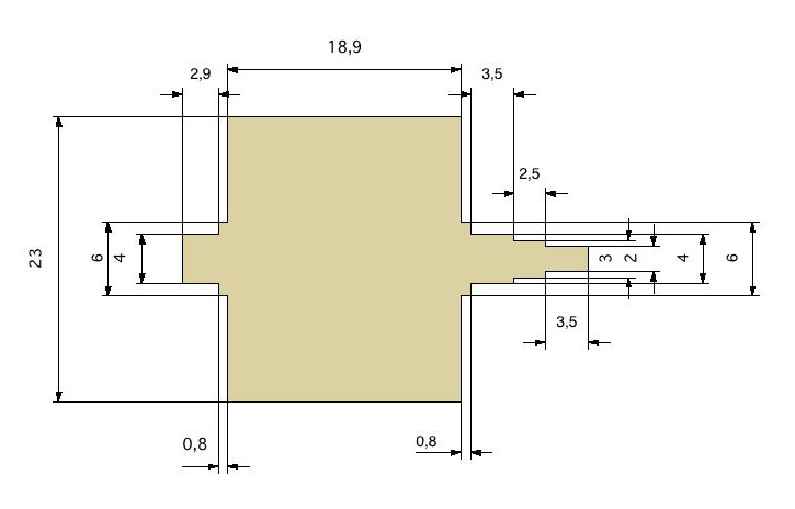
What I was trying to machine was this flywheel:

flywheel.JPG


I am trying to come up with a procedure that in the end will give me a flywheel with as little runout as absolutely possible.

I have access only to a regular 3-jaw chuck. I have collets up to 12 mm.

My plan is to start with a 25 mm diamer brass bolt and chuck it in the 3 jaw. It should be fairly easy even for me to machine everything to the right. As the flywheel is rather short in relation to the diameter, I plan to do this without support from the tailstock.

But what puzzles me is how to approch the short 4 mm diameter ball bearing axle to the left. I can not for the life of me figure out how to do this without having to rechuck the part after parting it off. The size of the flywheel in relation to the diameter of the axle prohibits turning the axle without support of the tailstock. But at the tailstock end I have just a feeble 2mm axle sticking out, so to me it seems like using the tailstock is no option.

And if I have to rechuck the part, is there any chance of getting acceptable results with a three-jaw chuck?

I would be very grateful for suggestions on how to approach this!

Best regards,
Hauk.

Hi,

Chuck a length of the 25mm stock in the 3 jaws and make sure that you leave enough stock out to form the flywheel. Machine enough Lenght of the 4mm short section so that it could safely be put in to the collet after you have machined it, you could do the short 6mm shoulder at the same time. Put the the machined 4mm section in to the collet and proceed to machine the 23mm diameter flywheel to Length and the rest of the shoulders , etc. These should now be concentric with the 4mm section that is in the collet. Once all the bits are machined to the correct length you can take the flywheel out of the collet and chuck the 23 mm section in the 3 jaw chuck and then part the long 4mm section to length. The 3 jaw chuck will not give you concentric rotation but because you are only parting off to length it should not matter. This is the quickest and easiest way of doing this, hope this helps.

Regards,

A.G
 
lensman57 said:
Chuck a length of the 25mm stock in the 3 jaws and make sure that you leave enough stock out to form the flywheel. Machine enough Lenght of the 4mm short section so that it could safely be put in to the collet after you have machined it, you could do the short 6mm shoulder at the same time. Put the the machined 4mm section in to the collet and proceed to machine the 23mm diameter flywheel to Length and the rest of the shoulders , etc. These should now be concentric with the 4mm section that is in the collet. Once all the bits are machined to the correct length you can take the flywheel out of the collet and chuck the 23 mm section in the 3 jaw chuck and then part the long 4mm section to length. The 3 jaw chuck will not give you concentric rotation but because you are only parting off to length it should not matter. This is the quickest and easiest way of doing this, hope this helps.

To a freshly scared junior machinist this sounds scary. Machining so so far out on a part supported in a 4mm collet sounds risky. Or does it go without saying that I should use the tailstock for support on the other end?

Regards, Hauk
 
Hauk said:
To a freshly scared junior machinist this sounds scary. Machining so so far out on a part supported in a 4mm collet sounds risky. Or does it go without saying that I should use the tailstock for support on the other end?

Regards, Hauk

That's why I suggested to rough out the longest part of the axle holding the wheel in the 3jaws.

3jaws:
1) Machine the left side to finish, make the 4mm dia. axle much longer than 2.9mm
2) machine the flywheel to size.
3) reverse the workpiece and machine the long portion of the axle oversize.

4mm collet:
4) hold the wp by the 4mm bearing and finish the long axle.

3jaws, again
5) part the 4mm axle to 2.9mm lenght.


If I were to make that flywheel, I'd use any steel rod from 6 up to 12mm to machine the axle in a collet and then press fit the brass flywheel on it.

Marcello


Along the lines of your "outboard bearing" idea, you could put on a temporary center

It would be machined from some stock and slip on over the outboard end and have a female center for the TS to bear against.

A TS center is probably going to be far more concentric than even a really good drill chuck.

Dave
 
Hauk said:
To a freshly scared junior machinist this sounds scary. Machining so so far out on a part supported in a 4mm collet sounds risky. Or does it go without saying that I should use the tailstock for support on the other end?

Regards, Hauk

Hi,
Anytime that you are machining any small diameter item, the tail stock center should be used. it is a good practice to get in to . Also if you use the above method use very light cuts and take your time.
You could also try the other methods suggested by other posts and see which one you are more comfortable with. If you prefer to machine the flywheel first and then slide it on to the machined shaft then you could either press fit it which means that your machining should be spot on to get the dimensions right or you could drill the flywheel to say 9mm and then locktite it on the shaft, but given the small length of the shoulders on the shaft this could get a little tricky.

Good luck,

A.G
 
and, if the axle dia. comes out a bit too small for the bore, You can enlarge it a little by knurling.
Gonna do that soon (once again ::)) for a piston rod in one of my Bernays.

Marcello
 
Hauk said:
As I don't have steady rest or the means for turning between centers, those options are out

Hauk,
Even if you do not have a face or drive plate for the lathe turning between centers is not that difficult. Most lathes are shipped with a dead center but a live center is really in my opinion a needed accessory.

A piece of steel pointed to 600 in the three jaw chuck will work fine. On the ships the chucks were really heavy and in a rolling sea it is risky to change for the drive plate so I have used the method quite a few times.

So all that is needed is a driving dog which can be made or they really do not cost all that much.

A steady rest is really only for special work and I can only think of a single job where I have used one. We used a Dumore tool post grinder to face the generator valves on one of the ships and the steady rest was used for support.

Dan
 
steamer said:
Along the lines of your "outboard bearing" idea, you could put on a temporary center

It would be machined from some stock and slip on over the outboard end and have a female center for the TS to bear against.

A TS center is probably going to be far more concentric than even a really good drill chuck.

Dave

Dave,
I agree that the run out of the drill chuck is the weak point of my suggestion.

If the drill chuck can be installed in the head stock a piece of scrap held in the jaws could be bored out to the OD of the bearing and that will be as true as the lathe.

Dan
 
Just a quick note to say that I machined the flywheel yesterday.
Everything seems to have worked out quite nice.

I did use the chuck in the tailstock as a improvised steady rest. I placed a piece of 12 mm brass in the chuck, and drilled it to accept the 8mm bearing mounted on the flywheel.

When I turned the axle nearest the 3-jaw chuck i just made a lot of parallell cuts with my parting tool. This is probably not the best practice, but I got a nice press fit for the bearing, so it can not have been all that wrong.

Thanks again for all the helpful suggestions!

Regards, Hauk

 
Another followup. Yesterday I clocked the flywheel after installing it in its cradle. Absolutely no runout, neither on the wheel itself or the axle. So this was a project about right for my skill level.
Time to move it up a notch!

flywheel.jpg


Best regards, Hauk
 

Nice work!

It's a good feeling when the clock doesn't even move. You take a closer look and ask yourself, "wait a minute, is dial even touching it?"

 
Hauk, Nice work.

I am looking forward to see the rest of the engine.

Dan
 
Dan Rowe said:
Hauk, Nice work.

I am looking forward to see the rest of the engine.

Dan

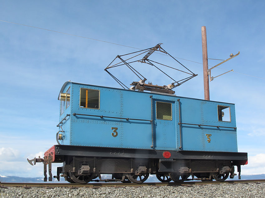
I think I have shown this one in another thread, but here goes anyway:
ferdig_ute_W_01.jpg


Scale: 1:45 Gauge: 22,22 mm
 
Back
Top