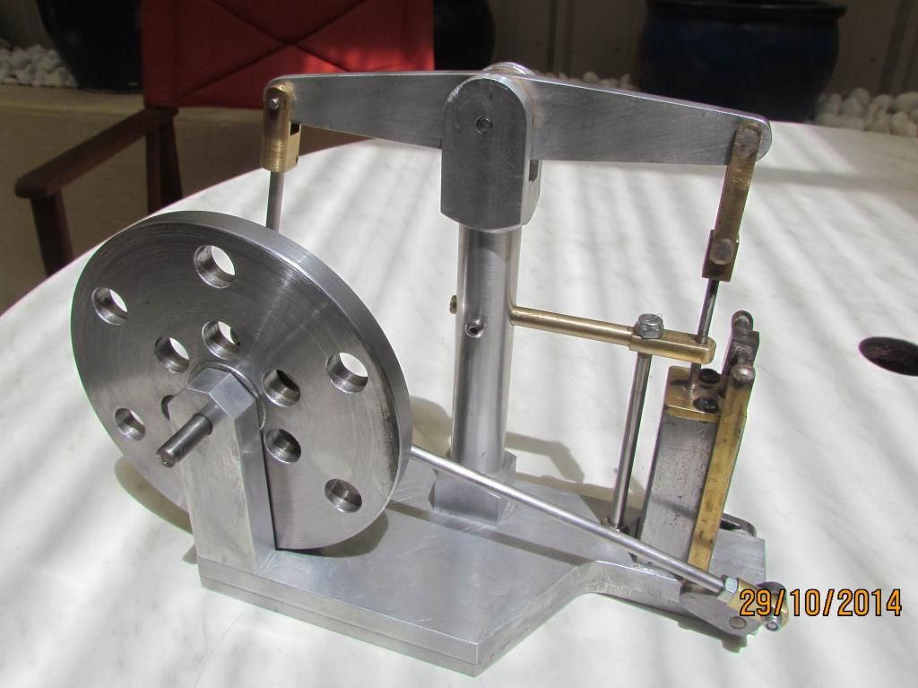
Bazmak Diary of Brian Rupnows Beam Engine

Home Model Engine Machinist Forum

Help Support Home Model Engine Machinist Forum:

This site may earn a commission from merchant affiliate links, including eBay, Amazon, and others.
Joined
Dec 12, 2012
Messages
2,220
Reaction score
1,288
Now that my mill was up and running i decided to make a simple engine
I have always been interested in a beam engine simple movement at slow speeds etc.I saw Brians thread and thought it would be ideal for all the same reasons he gave.Not too small and fiddly etc so i downloaded his plans.I had in mind to change a few things,and dims to suit available sections ,materials etc.As you all know changes dims is dangerous.Change one ,this affects others ad infinitum
I also decided to thread my progress just in case any newbies want to have a go.As Brian said,people all over the world have been making this engine and they wont all be alike.So to do the job properly.i printed off a set of plans and housed them in a ring binder,to keep track of dims changes
I started with the base.I could get 16thk alum for $25 + $25 for cutting local
I could get the same of the internet for $25 + $25 postage.This was going to be an expensive project.With a few ideas in mind i made the base from 2 pieces
10 thk top and 6 thk Bottom.These i cut out with my little woodworking bandsaw
I wonder if it will cut steel with the proper blade.I decided to make the flywheel support post from 2 pieces of 12x25 section each fixed to the base from the underside with 2 csk screws.This will save on matls,machining etc
and enable me to fit 2 skate bearings. TBC
 
turned the flywheel from 10 thk plt,by did that throw hot chips while singing like a choir in pain.I had fitted 7mm skate bearings so had to make shaft,eccentric to suit.Screwed down the posts and assembled.All good so far
 
Next was the beam and post.I cut and shaped the beam from 6mm alum
and made and fitted 2 top hat bearing bosses.The post was made basically as drawing from 25sq alum.I turned a 10mm long spigot and fixed from the underside of the base with a single M5 csk screw.I will also add the side fitting
as drg to give fixed alignment.I used my new fabbed angle plt as a fixture to mill the top slot
 
Next was the cylinder and head.The cylinder i made from 25sq mild steel
basically as drg,turned a 10 lg spigot,drilled and tapped M5 to fix thru the base from the underside with a csk screw.Photos show general setups.
I could not get the required brass section for the head so fabricated from
1/8" thk plt and a piece of 1/2" round (will silver solder later) All additional drillings will done later as assembly progresses
 
You are making good progress Baz, keep 'em coming.

Jim
 
Next was the piston,conn rod and linkages to both ends of the beam.For small shafts i try to use s/s
Tougher less prone to bending,does not rust and is precision ground in the smaller sizes.Mine was less than 1 thou under nom
and gave a good fit in a reamed hole.The piston i made from brass,faced,drilled and tapped in the lathe.Threaded the s/s rod
and fitted to the piston.Gripped in a collet and finished turned to a sliding fit in the piston.The linkage was as drg except i fitted
E washers to one end and bushed the beam with a 1/4dia x 1/4 lg brass bearing
The linkage from the flywheel end i had to mill down round brass to rectangle as i could not the requd section
The s/s pin in the beam was fixed with an M3 grubscrew to hold it and ensure the the motion is bearing on the brass link
Everything OK so far will assemble etc before stipping down and finishing off
 
Almost done but not yet posted.Replacement 5mm collet arrived
i could not grip 3/16 dia without it so waited.Now progressing
regards barry
 
I have been held up while i replaceded my old computer so then progressed,
with as Brian says the fiddly bits.As previously stated my collet set had the 5mm missing and sure enough thats what i needed to grip the 3/16 shafts
It did arrive with the missing 2mm so hats off to China.One point of interest
it appeared to be out of true,on closer inspection the slots were burred and full of swarfe.Touched up with a needle file and cleaned out the slots with a steel rule.All now Ok but will have to remember to check each one as i use them
Back to the fiddly bits,all ok and basically as drg.The shaft thru the base,i only soldered one end and grubscrewed the other.I wasnt happy to solder both ends with the shaft thru the base.Too permanent.On emistake was to make the 1/8 valve shaft 3/16,by the time i realised it was too late.Left it as it is for now,cant see a problem.Made the valve a precission fit dont see a need for lapping as its only a model.I screwed the end on to the 5/16 sq rather than have a fully soldered assy.The shaft and end were s/s and the valve bits brass.Question for Brian about valve timing i was going to set the piston at halfway and the valve at mid point of travel ???
 
Made a few more fiddly bits with no problems,the hard part is assembly
its like a 3 dim crossword puzzle.Needs some thought before i strip it all down to finish off.One small digression.I have been threading small rod in the lathe by hand with the tailstock pushed up to keep it square,anyway i tired of rapping my knuckles and made a tailstock die holder,from odd bits i had lying around
It works well so will maybe improve or remake properly as its very rough and ready.Made the barrel from an odd bit of 1" bar,but with hindsight would make it a bit longer fron 11/4" bar and recess for a 13/16" at 1 end and 1" at the other.The shaft was an odd piece of 3/8" s/s with grooves marked for thread length.Will make a new lever with a ball end.Its simple and only took me an Hour.Pictures tell the story
 
  • Like
Reactions: gus
Beam engine finished and run in on the lathe.All thats left is to strip it down
and tidy/clean up before reassembly etc etc.Still need to get my head around
best sequence for assy.Couple of questions for anyone in interested
My only 2 models were steam locos,dont want to show my ignorance but i assume that the drive comes from the flywheel side with the cylinder acting as a pump ??? Could this be reversed with compressed air or steam driving the piston to turn the flywheel ??? http://s1327.photobucket.com/user/bazmak47/media/finish01_zpsb3d4d84b.jpg.html?sort=3&o=2
 
Looking great Baz. I had to get my own beam engine out and set it up beside my computer to have a close look. It's been a long time since I built it. I can't remember if I put it in the plans or not, but the air inlet fitting goes in the second hole down from the top of the cylinder block. the other two holes are blocked off, except for the hole at the extreme bottom which is left open. The "high" part of the cam lobe with greatest lift is set up to be exactly opposite of the "throw" on the crankshaft. When the crankshaft is turned so the connecting link journal is horizontal to the center of the crankshaft and facing towards the central tower, the fiddly bit that the link from the cam attaches to should be almost straight up, and the one on the other side of the base should be facing down on an angle that almost lets the end of it hit the table under the base. The sliding valve mechanism will be in a fully "down" position. I had made my cylinder block from brass, so was able to silver solder plugs into the two holes which need to be plugged. Your cylinder block appears to be made from steel, so you can do the same, or you can make up a couple of plugs and Loctite them into the holes. That is how the timing is set up on my engine.---Brian
 
Last edited:

Latest posts

Back
Top