Auto Reversing Winch

Home Model Engine Machinist Forum

Help Support Home Model Engine Machinist Forum:

This site may earn a commission from merchant affiliate links, including eBay, Amazon, and others.

Brian Rupnow

Design Engineer
Project of the Month Winner
Joined
May 23, 2008
Messages
15,259
Reaction score
8,544
Location
Barrie, Ontario, Canada
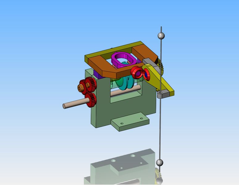
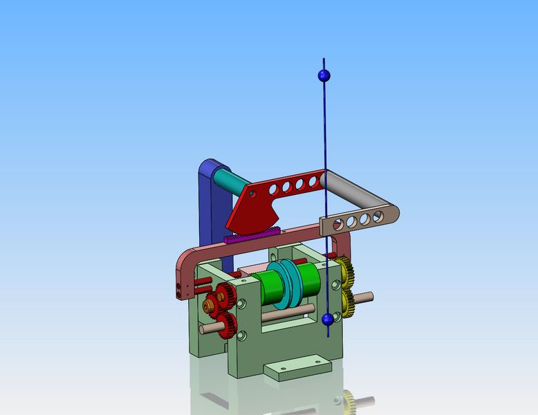
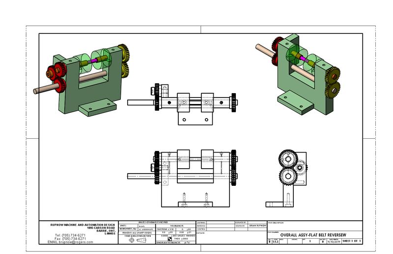
After completing the vertical hit and miss engine, I have tried three or four different ways to make the engine go in and out of "hit and miss" no load operation and "only hit-no miss" loaded operation. Some of the things I tried were successful, but they demanded that I be part of the operation. I wanted something totally automatic to do this job, where I wouldn't have to be involved. My absolute best video of the engine doing what I wanted was with the engine turning a winch to raise a load. I have done a great deal of thinking how this could be done without needing me to engage and disengage the winch. So---I'm a bit early into the game here, but far enough to share a concept. Last year I designed and built a mechanism that would reverse a flat belt drive, in order to mimic the reversing of a belt drive from a line shaft. It worked. It was rather crude and "sorta" worked but after making a couple of videos of it in operation it has set on a shelf in my office and never been touched again. However--there was a little bit of magic at work there, because when the lower shaft was driven by a motor, the two semi transparent drums turned in opposite directions. Now, imagine a winch drum that sets between the two outside drums and is not keyed to the shaft. It is actually a bit narrower than the space. Think "dog clutch". If I had a mechanism that would slide the drum to the left or to the right, it would rotate clockwise when forced up against the driven drum on one side, and counterclockwise when it was forced up against the other drum. Now think of two mechanical "bobs" attached to the winch line, that contact an arm at maximum height and forces the moveable winch drum against the opposite driven drum. This reverses the rotation of the winch drum and pays out line until at minimum height the second "bob" contacts the same arm and swings it over against the other driven drum. There won't be enough force to make the faces a friction drive. It will have to be a dog clutch that engages very easily. Will share more with you fellows after I have thought this out a bit more clearly in my head.---Brian
pcQ9FW.jpg
 
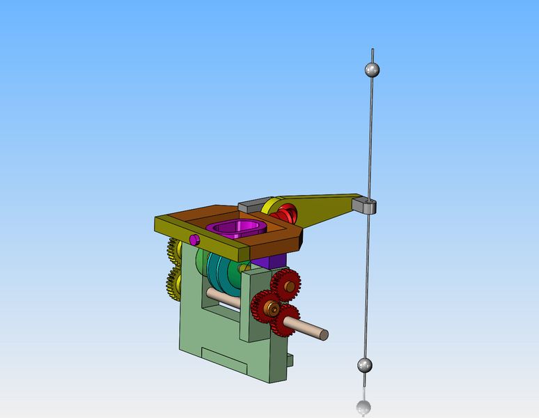
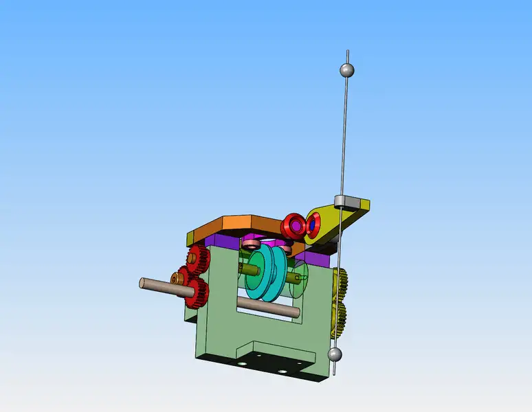
I have worked out all the design of the self reversing winch. When the "bobs" on the string hit the arm which is attached to the bevel gear, the bevel gear rotates (only a little bit) and causes the second bevel gear to rotate. The carrier rotates (again only a little bit) and the bearings attached to it cause the winch drum to move to either the right or to the left. As soon as the winch drum rides up against either semi transparent drums, the built in dog clutch (which you can't see in the models) engage and turn the winch drum either clockwise or counterclockwise until the other "bob" attached to the string hits the arm and moves the winch over against the other drum which is rotating in the opposite direction.
QtqMMQ.jpg

T26ab4.jpg

41i34l.jpg
 
Brian,

I can hardly wait to see this in action. My mind had contemplated the "bobs," and I sorta thought something like CW/CCW switching somehow, but I couldn't get any further than that. Your wonderful design experience and innate curiosity about such things has come through again and now I can see this working like you wanted.

Thanks again for taking us along for the ride.

--ShopShoe
 
Shopshoe--Many years ago one of my kids had to write a story for school. My son wrote a story about porcupines. All I remember now is that he said the porcupine was "slow and dull witted". Today I feel a bit like the porcupine. I may rethink the design of this mechanism. Sometimes I have to design what I dimly see in the back of my mind before I can realize that there is a quicker/better way. Will do some more work on it tomorrow.---Brian
 
One of the problem to watch for in this type of mechanism, a self-modifying mechanism, is that once the switching action starts it may cut off the cause that started it and only go part way. A sure way to cope with this is to insert an hysteresis function like you have in a toggle switch. Once the action is initiated and reach a certain point a spring pushes the mechanism into an irreversible motion.
In other words the bob motion should not be cause the inversion but should place in motion the mechanism that that will reverse the drive without further assistance from the bob. Some kind of a snap action.
 
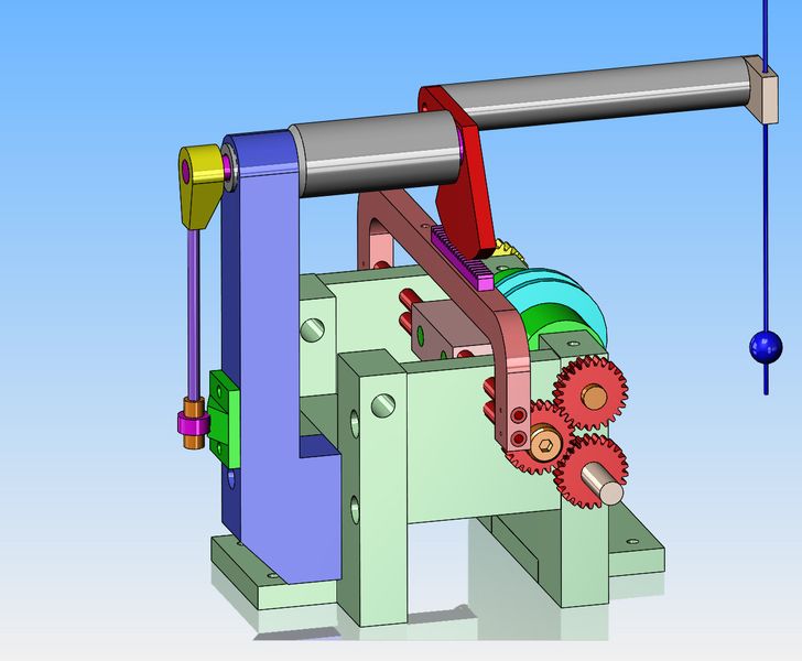
I've been rethinking this mechanism. This picture shows the current state of what I am starting with. I have spent a few hours this morning rethinking the design to let me use more of the parts that I already have. The model shows my change in design direction.
V4lXZP.jpg

hepuAV.jpg
 
Tornitore45 ---You are correct. A "snap" action as you suggest would be best. The other thing that will work as long as there is no counterforce is a detent ball. I haven't thought too much about either yet, although a pair of detent balls acting on the red part with the gear cut into it would be fairly easy.
 
Yes but. The way I visualize the operation is that the belt start mowing from one pulley (drum) as it does it comes a point where is somewhere in between. Half on the Up Pulley and half on the Down Pulley, this situation can not continue to advance the derailleur to the other pulley. I may have not captured completely the design. While a ball detente is good at keeping a position is not very effective at "sucking into" the final position from far away. I think you have all feature to easily add a spring acting on the arm that will flip to the other position as soon as the belt is 1/2 way off the pulley and on a 1/2 on an idler, that is the point of no return where the bob does not need to drive the switch and the spring finish the switch.
 
They typical mechanism for laying down a cable or hose is a reversing screw with a high pitch and a single short tooth that can change its angle to follow the path and long enough not to be caught in a track for the opposite movement. Bait reels has such a mechanism. However the cutting of the screw thread is not simple to do. Bait casing screw is manufactured on a Swiss Mill. I have used this mechanism for an air pump that had to get the most life out of a four AA batteries. Prototype and life testing was completed before the company changed ownership and the product was stopped.

You appear to have gears and racks. One requirement of the laying guide is work in take up and let out of the cable and allow change of direction at any point. Change direction can be easily done by a oval shaped rack track which could be made by a gear on the guide consisting of four parts: two straight racks with half of a circular gear connecting the two. The shaft of the drive gear fixed will thus move the guide back and forth and also up and down at the ends. Less effective would be a spring loaded short vertical rack that is pushed away from the long rack by the gear and at the same time the teeth in the short rack will move up and down to then have the spring push the drive gear into the other long rack.
 
Last edited:
Brian this has no comparison to what you are doing but it is a interesting mechanism
.<iframe width="560" height="315" src="" frameborder="0" allow="accelerometer; autoplay; encrypted-media; gyroscope; picture-in-picture" allowfullscreen></iframe>
 
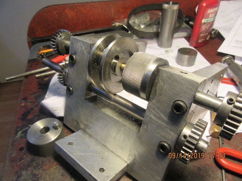
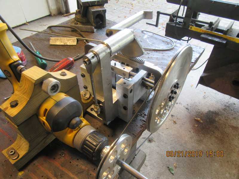
Today I made the winch drum and put the groove in each side that gives me the "dog clutch". The knurled round part setting beside the new winch drum is one of the original parts that has been drilled and had a piece of 1/4" shaft Loctited into it. (the other existing drum is laying at the front of the mechanism.) Due to the gearing, the two knurled drums rotate in opposite directions--they are locked to the shaft which is actually three individual shafts--right shaft fixed to right knurled drum, left shaft attached to the left knurled drum, and a floater shaft between the two which is not powered. The winch drum is shifted from one side to the other to reverse it. There is going to end up being a very small gap between the winch drum and the 1/4" shafts that are mounted in the existing knurled drums because the winch drum must not engage both drums at the same time.
lHBwe9.jpg
 
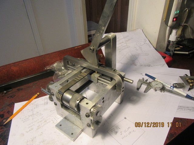
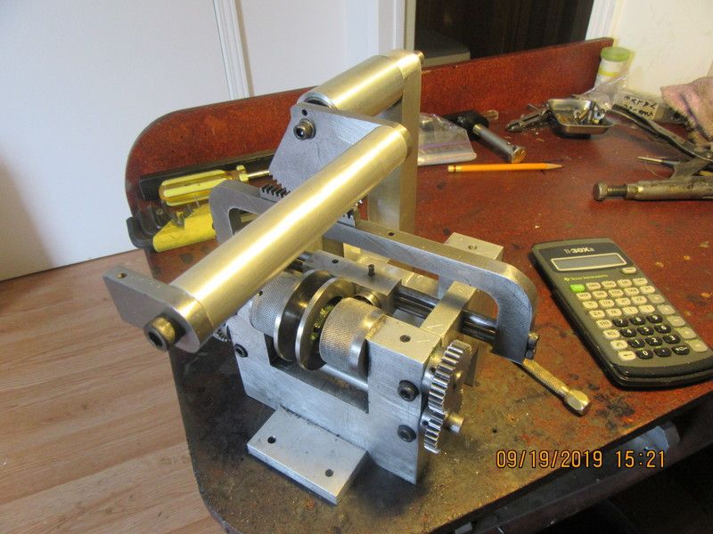
The reversing winch mechanism is finished. It operates very smoothly on the test bench. The pivot for the gear segment got changed from a shoulder bolt to a 3/8" shaft with ball bearings, to prevent binding at the pivot. Tomorrow I will do a dynamic test. If it is successful, then I will post a video.
g3OQV0.jpg
 
There is going to end up being a very small gap between the winch drum and the 1/4" shafts that are mounted in the existing knurled drums because the winch drum must not engage both drums at the same time.
During which moment the weight will be free to crash to the floor? Or have I missed something (admittedly I have not been following closely)?
 
Charles, to know whats going on here, you have to have followed my vertical hit and miss engine thread.---Brian
 
I think I am going to have to add a counterweight to the other side of the gear segment axis. I have tried to make everything very "free" so that nothing will bind. I've succeeded so well that the weight of the offset arm makes the winch drum change sides.
 
This morning was the first "trial run" of the system, and I am quite happy with the results at this time. The winch drum does reverse as I had hoped, and does so quite smoothly. I am going to add something similar to a ball indent pin to hold the mechanism in forward or reverse gear so it doesn't move from vibration as it runs. Thanks for having a look.---Brian
 
Not the worlds greatest picture, but you can see the spring steel arm with a "wheel" on the end of it. That wheel bears against a ramp that has it's high spot in the center. This gives a very definite feel to the mechanism being engaged for either clockwise or counter clockwise. It no longer will allow the arm to drop due to the effect of gravity.
zmtKkW.jpg
 

Latest posts

Back
Top