arnoldb
Well-Known Member
- Joined
- Apr 8, 2009
- Messages
- 1,792
- Reaction score
- 12
With a couple of compressed air/steam engines under my belt, I feel like a foray into the world of flame lickers...
I have quite a couple of plans available, but for most I would require items (mostly small ball bearings) that are unobtainable locally, and hence require running the gauntlet of E-Bay and poor and unpredictable postal services to Namibia.
I nearly glossed over Phil Duclos's Little Blazer because of some of the small screws needed, but then I realised I could make them myself, so I started sourcing raw materials:
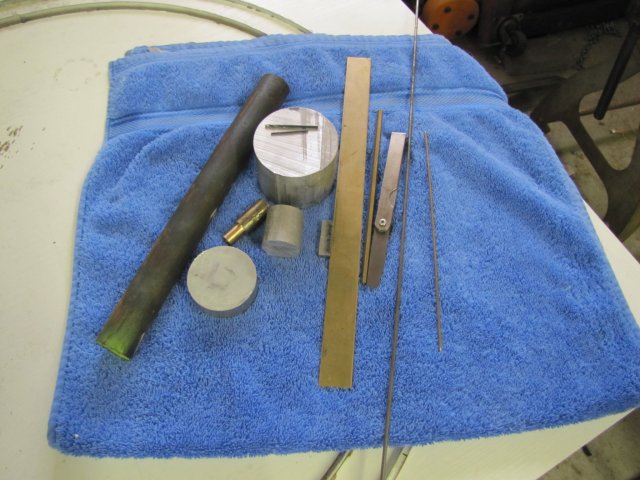
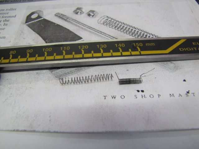
Bits of the above will go into the build. The big round piece of aluminium is to make the base from; I can't find a rectangular piece of suitable size, and the feeler gauge will have its one blade sacrificed for the valve spring.
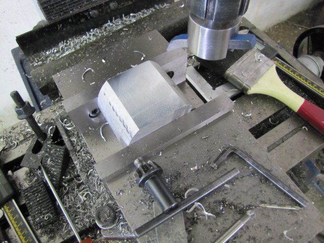
The build was actually started last Sunday; I milled the big round bit of aluminium down to form the rectangular block from which the engine base is to be built First roughed it out to a rectangular block:
Measured and marked up final dimensions:
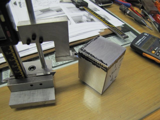
Finally down to size and as square as I have ever gotten anything...:
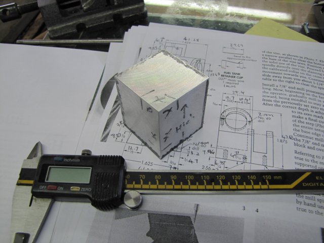
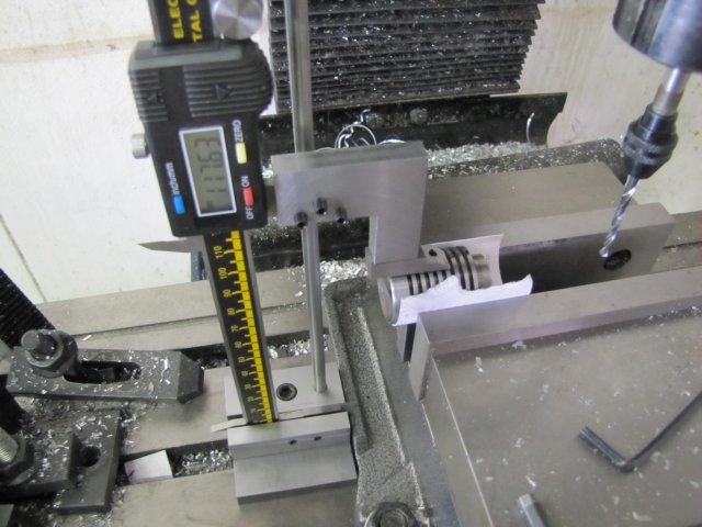
Then I calculated and marked out the bit that has to be faced off at a 20 degree angle. Nothing fancy; just some trigonometry to calculate offsets, and draw a line. I used the height gauge on the mill vise to check that I clamped up the block at the required angle:
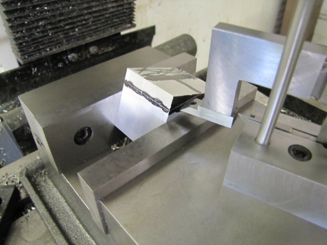
And faced off with the flycutter:
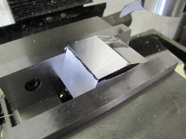
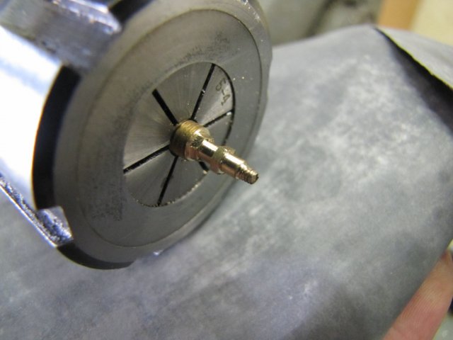
I used a small file to de-burr the cut edges while still clamped up, and then used an obsolete needle valve chucked up in the dremel chuck adapter to locate the one corner as accurately as possible by eye; Mr Duclos used a wiggler's needle for this step:
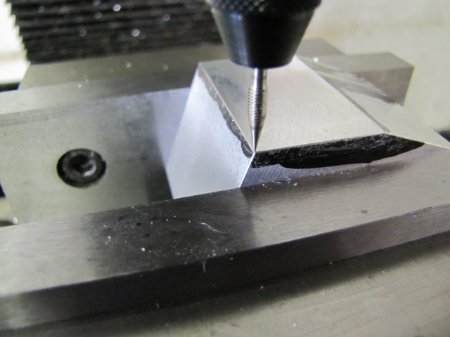
The mill's x and y dials were zeroed at this point for the next steps.
I dialled in the 12.7mm offsets needed on both X and Y and spotted the location with a center drill, then drilled about 13mm deep with a 6mm drill:
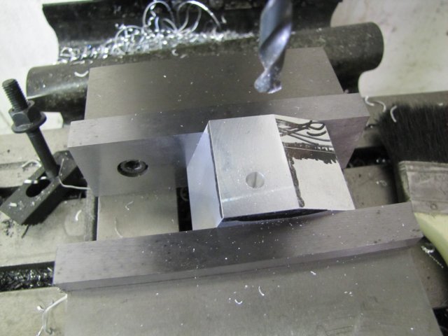
This was followed by a 16mm drill:
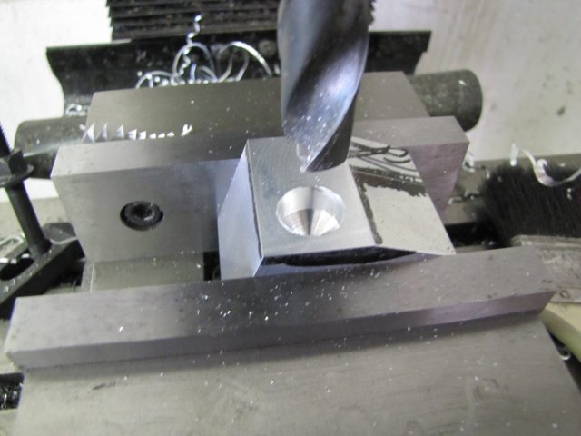
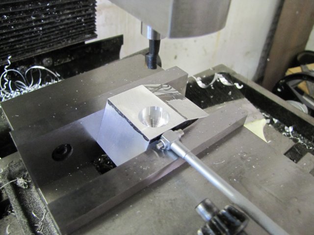
And finally the boring head to get the hole to 17.4mm - I used the 12-19mm telescopic gauge to measure; at the larger end of it's range, it's not entirely necessary to get its handle in alignment with the bore of a hole, as long as it's head is kept square to the bore central axis:
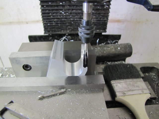
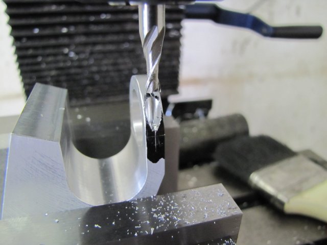
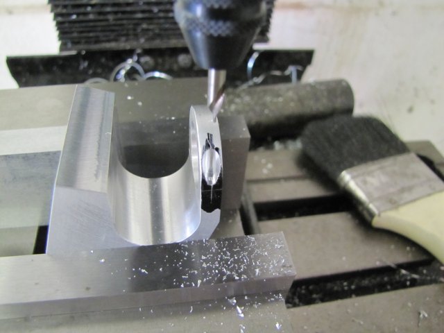
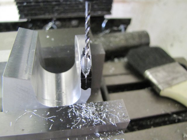
The boring was followed by offsetting the Y axis further to locate the position for the valve rod guide, and spotting and drilling a 2mm hole for the valve rod:
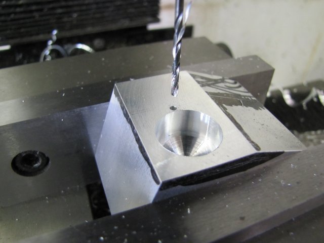
I hope this does not bite me in the back; Mr Duclos specified a #49 drill which is between 1.8 and 1.9mm - and I decided to go for a 2mm valve rod... It will be a bugger to turn up a bushing if needed :big:
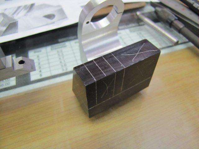
Next followed some more markout; a lot of it was just to help me visualize the base and to double-check that things were still going to plan...:
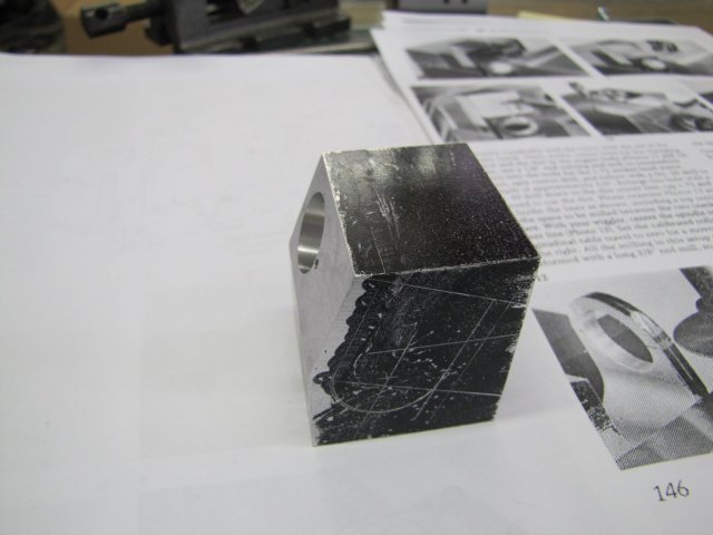
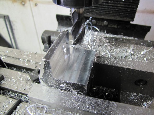
More milling followed; pretty much following Mr Duclos's instructions:
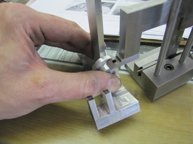
The next photo was originally only intended to show how I use a square in the vise to set up a part a distance from the bottom of the vise when I don't have suitable parallels around, and accuracy is not of the greatest importance. When viewing the photo on-screen however, I noticed some additional details with some valuable personal lessons behind it. Original intent: I have a small flat square with a wide edge on the short end. By putting the wide edge on the vise bed, and pressing it down with my middle and ring fingers, it is held fairly secure to the vise bed. Then I use my thumb and forefinger to squeeze the part to the vertical edge, and tighten up the vise (The milling cutter is quite a way away from my hand and not dangerous here):
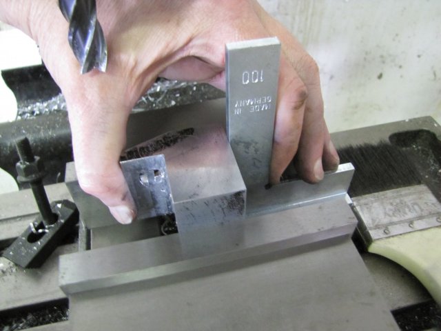
Now the anecdotes; there's three here.
1. Just to the right, and slightly above the bottom of the milling cutter is a scar on my hand. That has been there for about 15 years, and the damage was done by my "small" 115mm (4.5") angle grinder. I was making a security gate for a friend and was grinding away my (bad!) welding marks; using the hand in picture to hold the gate, and my right hand to run the grinder. I was getting tired, and it only took a minute lapse in concentration and the cut was done; it could easily have been much worse, but fortunately not. I have never since worked my "small" grinder with one hand only; the work gets clamped down, and both hands works the grinder. If I feel I'm getting tired, I stop - a grinder tires one out quickly.
2. If you follow the very top of the square from left to right, about a quarter of the way just above the edge there is a small scar on my hand. That was done by a thin Dremel cutting disc breaking; my hand happened to be in line of the disintegrating disc. Personal lesson learned; keep as much as possible of body and soul out of the spinning line of stones and discs - even a small Dremel needs to be treated with respect.
3. To the left of, and below the top of the square, there's a scratch on my finger. Shrek the African Gray parrot did that this morning; he was in a bit of a bad mood. Lesson - animals (and people!) have bad moods; these I just have to accept in the spirit of love
Enough digressing and back to the build.
Once again the impromptu center finder I mentioned earlier comes into play to locate the center for the rounded bottom "inside curve" of the base:
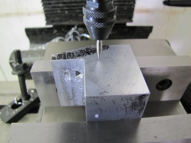
Though it looks like I'm only working to one line, there is a tiny prick mark left by the compasses when I did the last layout. If you don't believe me, click here for a bigger photo.
A 6.5mm hole was drilled, followed by a 19mm (my biggest!) drill:
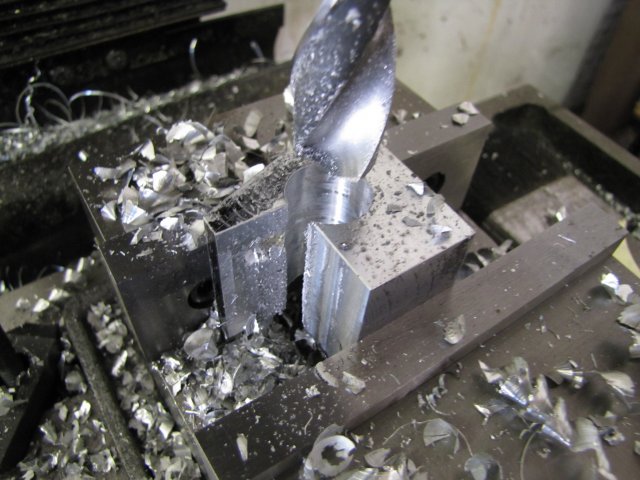
I was concerned about the big drill doing an interrupted cut, but as quite a lot of its tip had to follow the pilot hole, things went well. The drill was still under size, so if it strayed a bit, there was not too much of a concern.
The 19mm hole was then opened up to 22.2mm with the boring head:
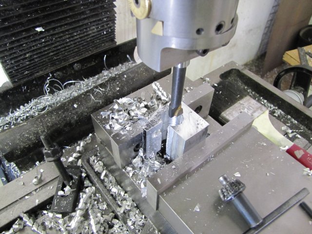
Up to this point, I've been fairly brutal with the workpiece - taking fairly big cuts at good rates of feed. For the next phase I slowed down a bit, as workholding was becoming less secure. After de-burring, I started by using a square to set the workpiece vertical to the angled face in the vise; once again using the method with the square - and - fingers mentioned earlier, with the centerline of the bore from the previous step above the vise jaws, and some old business cards between vise jaws and the workpiece to get things as tight as possible. Then I milled down the back to meet the bored hole - as the face end is getting thin and high above the vise, I took just 1.5mm down-cuts at a time staying away from the final thickness:
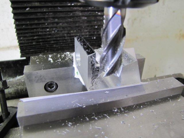
The other side followed:
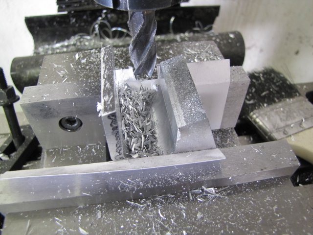
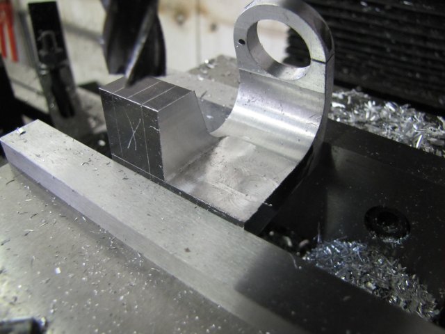
Milling down the "step" in the base proved problematic for workholding. As the workpiece was getting whittled away, there were less - and more irregular - features to clamp down. I _COULD_ have mounted my mill vise's swiveling base, but getting everything in tram would have required a lot of fussing about. So I gambled on a "back-to-basics" method. I clamped the workpiece directly to the mill table with thick bits of paper between it and the mill table, as well as between its top and the clamp. Once again I used the small square with the offset base to align the face:
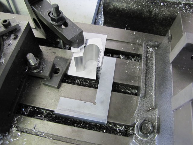
The single clamp point is far from ideal - but I didn't want to clamp through the bored hole in the face, as clamping there could distort it...
Then started milling away - lightly. Several passes in Y to get to depth, offset X and repeat the Y Part-way through:
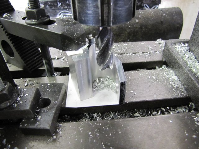
Before I hit final dimensions, I checked with the square again - just to make sure nothing moved. It didn't
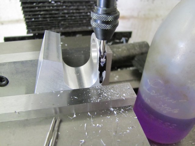
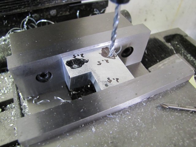
Before removing more metal from the base, I decided to drill and tap the mounting holes, as well as the mounting hole and screw-down for the retainer clip for the burner:
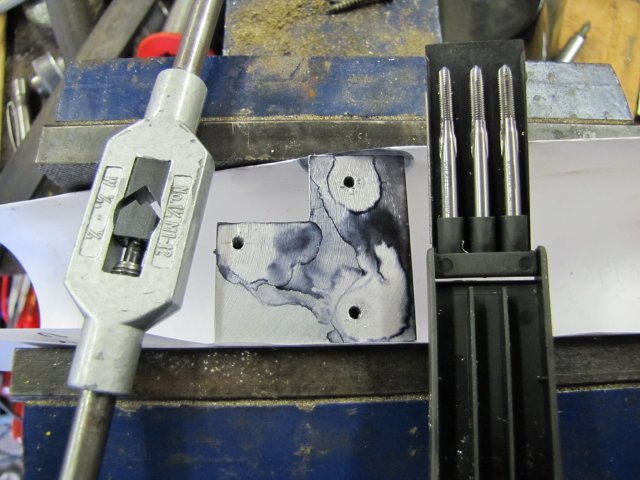
And tapped that lot - all M3 instead of 1-72 and 2-56; I deviated from the plans a bit for "comfort" :big::
At this point, and about eight straight hours from starting the day's machining, my cellphone rang. I tried to answer the workshop electronic calculator... - That seriously meant time to pack up; I don't want any more scars. So, no more machines, but I still wanted to do a bit more...
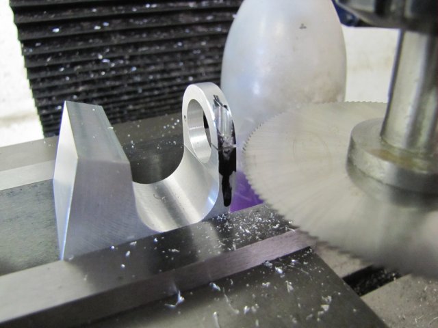
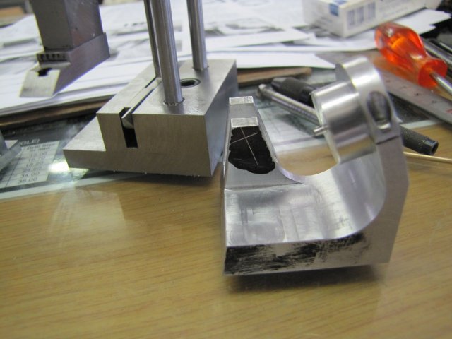
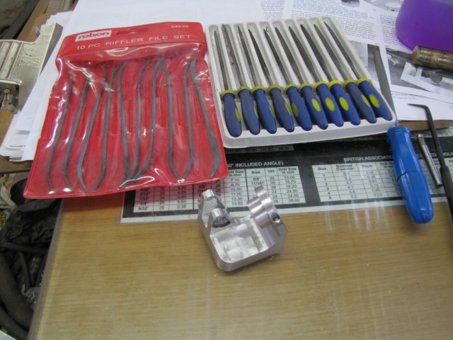
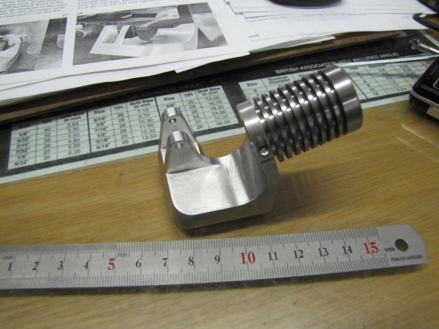
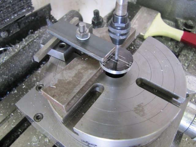
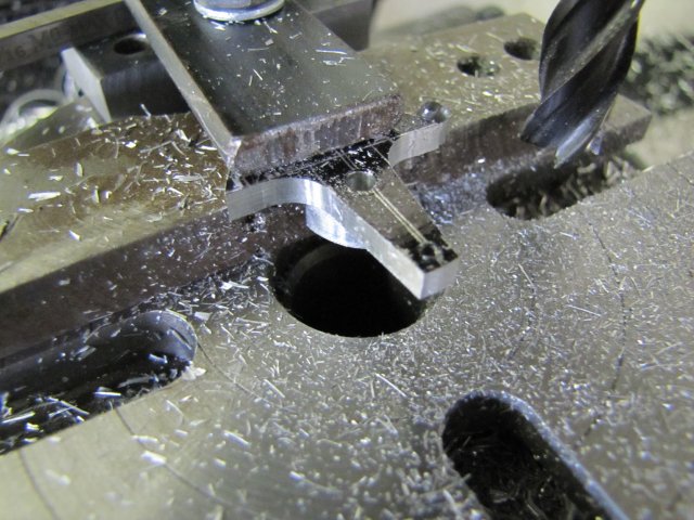
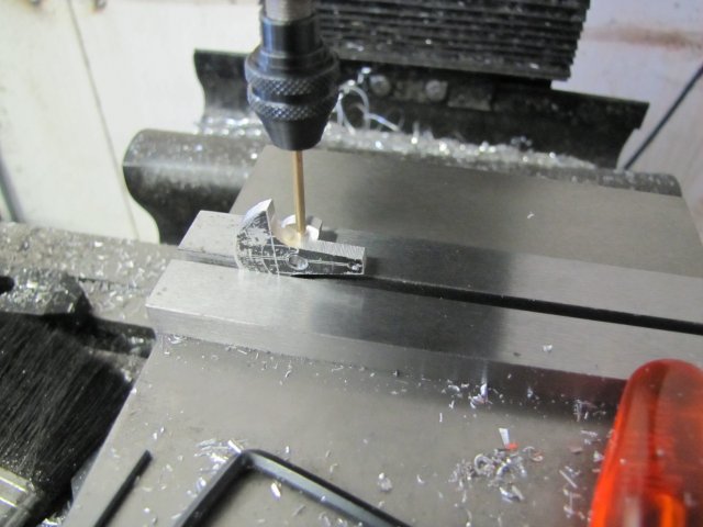
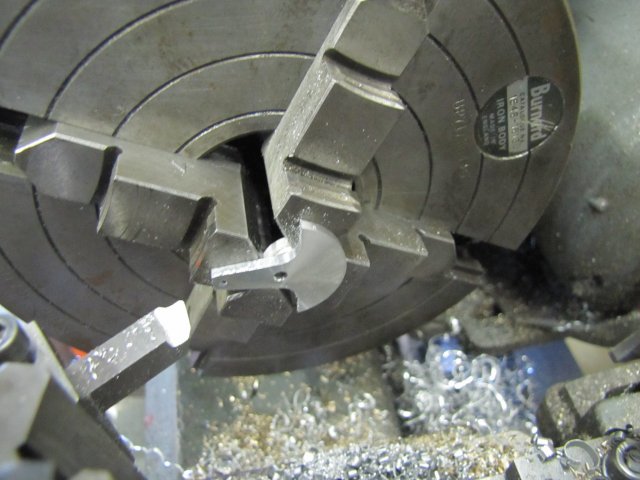
The base needed rounding over around the cylinder mount. Mr Duclos does that using a rotary table on the mill. Filing buttons would do as well, but machining was out for me at this stage, so I deeply scribed the curve using a conveniently sized bit of rod as a guide and trimmed the excess off with a junior hacksaw. Then filed roughly to the scribed line with a big coarse file:
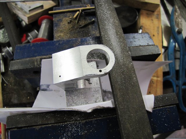
Followed by my favourite "smallish" file - down to the line by eye and judging "squareness" by eye as well:
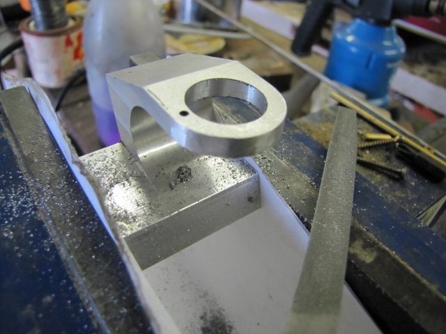
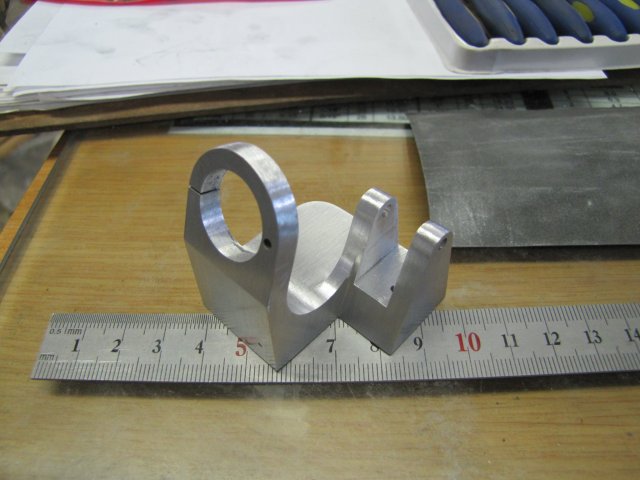
Took all of 5 minutes to saw, coarse file, and fine file down; would have taken longer to turn up filing buttons!
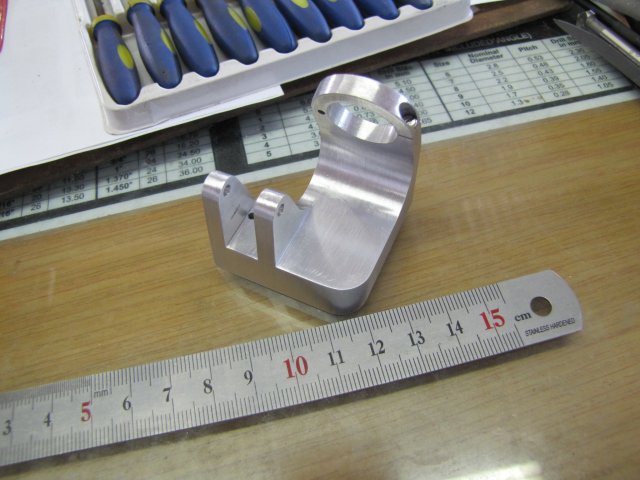
A quick "lick" around the filed edge with some emery wrapped in the self-same rule in the next photo, and that's where I packed it in for the day:
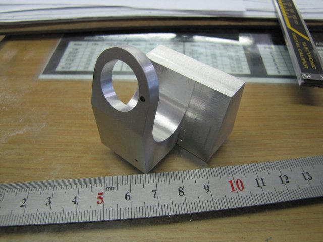
I've actually had a very active day in the workshop; it feels like I've been to the gym from just contorting to check angles for holes and so on. And of course, cranking the mill wheels - lots of exercise there! - :big:
This was a bit of a marathon post; I value all questions, input and criticism!
Regards, Arnold
I have quite a couple of plans available, but for most I would require items (mostly small ball bearings) that are unobtainable locally, and hence require running the gauntlet of E-Bay and poor and unpredictable postal services to Namibia.
I nearly glossed over Phil Duclos's Little Blazer because of some of the small screws needed, but then I realised I could make them myself, so I started sourcing raw materials:

Bits of the above will go into the build. The big round piece of aluminium is to make the base from; I can't find a rectangular piece of suitable size, and the feeler gauge will have its one blade sacrificed for the valve spring.
The build was actually started last Sunday; I milled the big round bit of aluminium down to form the rectangular block from which the engine base is to be built First roughed it out to a rectangular block:

Measured and marked up final dimensions:

Finally down to size and as square as I have ever gotten anything...:

Then I calculated and marked out the bit that has to be faced off at a 20 degree angle. Nothing fancy; just some trigonometry to calculate offsets, and draw a line. I used the height gauge on the mill vise to check that I clamped up the block at the required angle:

And faced off with the flycutter:

I used a small file to de-burr the cut edges while still clamped up, and then used an obsolete needle valve chucked up in the dremel chuck adapter to locate the one corner as accurately as possible by eye; Mr Duclos used a wiggler's needle for this step:

The mill's x and y dials were zeroed at this point for the next steps.
I dialled in the 12.7mm offsets needed on both X and Y and spotted the location with a center drill, then drilled about 13mm deep with a 6mm drill:

This was followed by a 16mm drill:

And finally the boring head to get the hole to 17.4mm - I used the 12-19mm telescopic gauge to measure; at the larger end of it's range, it's not entirely necessary to get its handle in alignment with the bore of a hole, as long as it's head is kept square to the bore central axis:

The boring was followed by offsetting the Y axis further to locate the position for the valve rod guide, and spotting and drilling a 2mm hole for the valve rod:

I hope this does not bite me in the back; Mr Duclos specified a #49 drill which is between 1.8 and 1.9mm - and I decided to go for a 2mm valve rod... It will be a bugger to turn up a bushing if needed :big:
Next followed some more markout; a lot of it was just to help me visualize the base and to double-check that things were still going to plan...:

More milling followed; pretty much following Mr Duclos's instructions:

The next photo was originally only intended to show how I use a square in the vise to set up a part a distance from the bottom of the vise when I don't have suitable parallels around, and accuracy is not of the greatest importance. When viewing the photo on-screen however, I noticed some additional details with some valuable personal lessons behind it. Original intent: I have a small flat square with a wide edge on the short end. By putting the wide edge on the vise bed, and pressing it down with my middle and ring fingers, it is held fairly secure to the vise bed. Then I use my thumb and forefinger to squeeze the part to the vertical edge, and tighten up the vise (The milling cutter is quite a way away from my hand and not dangerous here):

Now the anecdotes; there's three here.
1. Just to the right, and slightly above the bottom of the milling cutter is a scar on my hand. That has been there for about 15 years, and the damage was done by my "small" 115mm (4.5") angle grinder. I was making a security gate for a friend and was grinding away my (bad!) welding marks; using the hand in picture to hold the gate, and my right hand to run the grinder. I was getting tired, and it only took a minute lapse in concentration and the cut was done; it could easily have been much worse, but fortunately not. I have never since worked my "small" grinder with one hand only; the work gets clamped down, and both hands works the grinder. If I feel I'm getting tired, I stop - a grinder tires one out quickly.
2. If you follow the very top of the square from left to right, about a quarter of the way just above the edge there is a small scar on my hand. That was done by a thin Dremel cutting disc breaking; my hand happened to be in line of the disintegrating disc. Personal lesson learned; keep as much as possible of body and soul out of the spinning line of stones and discs - even a small Dremel needs to be treated with respect.
3. To the left of, and below the top of the square, there's a scratch on my finger. Shrek the African Gray parrot did that this morning; he was in a bit of a bad mood. Lesson - animals (and people!) have bad moods; these I just have to accept in the spirit of love
Enough digressing and back to the build.
Once again the impromptu center finder I mentioned earlier comes into play to locate the center for the rounded bottom "inside curve" of the base:

Though it looks like I'm only working to one line, there is a tiny prick mark left by the compasses when I did the last layout. If you don't believe me, click here for a bigger photo.
A 6.5mm hole was drilled, followed by a 19mm (my biggest!) drill:

I was concerned about the big drill doing an interrupted cut, but as quite a lot of its tip had to follow the pilot hole, things went well. The drill was still under size, so if it strayed a bit, there was not too much of a concern.
The 19mm hole was then opened up to 22.2mm with the boring head:

Up to this point, I've been fairly brutal with the workpiece - taking fairly big cuts at good rates of feed. For the next phase I slowed down a bit, as workholding was becoming less secure. After de-burring, I started by using a square to set the workpiece vertical to the angled face in the vise; once again using the method with the square - and - fingers mentioned earlier, with the centerline of the bore from the previous step above the vise jaws, and some old business cards between vise jaws and the workpiece to get things as tight as possible. Then I milled down the back to meet the bored hole - as the face end is getting thin and high above the vise, I took just 1.5mm down-cuts at a time staying away from the final thickness:

The other side followed:

Milling down the "step" in the base proved problematic for workholding. As the workpiece was getting whittled away, there were less - and more irregular - features to clamp down. I _COULD_ have mounted my mill vise's swiveling base, but getting everything in tram would have required a lot of fussing about. So I gambled on a "back-to-basics" method. I clamped the workpiece directly to the mill table with thick bits of paper between it and the mill table, as well as between its top and the clamp. Once again I used the small square with the offset base to align the face:

The single clamp point is far from ideal - but I didn't want to clamp through the bored hole in the face, as clamping there could distort it...
Then started milling away - lightly. Several passes in Y to get to depth, offset X and repeat the Y Part-way through:

Before I hit final dimensions, I checked with the square again - just to make sure nothing moved. It didn't
Before removing more metal from the base, I decided to drill and tap the mounting holes, as well as the mounting hole and screw-down for the retainer clip for the burner:

And tapped that lot - all M3 instead of 1-72 and 2-56; I deviated from the plans a bit for "comfort" :big::

At this point, and about eight straight hours from starting the day's machining, my cellphone rang. I tried to answer the workshop electronic calculator... - That seriously meant time to pack up; I don't want any more scars. So, no more machines, but I still wanted to do a bit more...
The base needed rounding over around the cylinder mount. Mr Duclos does that using a rotary table on the mill. Filing buttons would do as well, but machining was out for me at this stage, so I deeply scribed the curve using a conveniently sized bit of rod as a guide and trimmed the excess off with a junior hacksaw. Then filed roughly to the scribed line with a big coarse file:

Followed by my favourite "smallish" file - down to the line by eye and judging "squareness" by eye as well:

Took all of 5 minutes to saw, coarse file, and fine file down; would have taken longer to turn up filing buttons!
A quick "lick" around the filed edge with some emery wrapped in the self-same rule in the next photo, and that's where I packed it in for the day:

I've actually had a very active day in the workshop; it feels like I've been to the gym from just contorting to check angles for holes and so on. And of course, cranking the mill wheels - lots of exercise there! - :big:
This was a bit of a marathon post; I value all questions, input and criticism!
Regards, Arnold


