Someone from the Axminster forum that I also posted about my Arduino project did a lot of work getting my code to run on an Arduino NANO.
He posted his experiences there, so I thought I would pass it along to this forum.
Jenny
Hi all,
As I was looking for a way to set up a tachometer on my mini-lathe and mini-mill, I stumbled upon this post. It was a great relief: what I wanted already existed and was described in great details. So I asked Jenny about this code and she kindly answered me and sent it to me very fast. Then, I started to play with it.
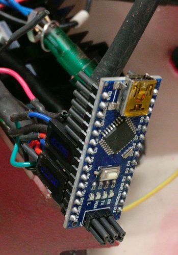
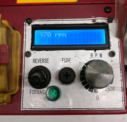
I decided to use an Arduino nano rather than an Arduino Uno so it could fit within the lathe enclosure, with a window cut on the top for the display. As the LCD screen takes almost all the space in the top panel, this implied moving the green power indicator and to remove the yellow fault light. One consequence of moving the fault LED was to add a new feature to the tachometer so it replaces this notification: I wanted the LCD monitor the fault line and display a “FAULT!!!” message message when needed. As the Arduino nano can use interrupts on only two pins, I therefore started by moving around the pins: yellow positive wire to pin2, LCDCL to pin 3, LCDCS to pin 4 and LCDDI to pin 5. With this setting, I could use one interrupt for the LCDCL (clock for RPM data transmission) and another interrupt for the fault line.
I also wanted to change the interrupt routines to use a more explicit API, using attachInterruptinstead of EIMSK/EICRA/SIGNAL(INT1_vect)that were used on the original code. In the Interrupt Service Routine, I also wanted to reduce memory usage by extracting only the single LCDDI bit (instead of the full 8 bits PIND register). This failed dramatically! I tried a lot of different things in the past few weeks and was not able to achieve my goal. It seems to me that despite the board will be idle most of the time (the rotation rate is refreshed only every 750ms), when it is refreshed the bits arrive fast and the board has a hard time coping with the interrupts. The ISR must therefore be really really short to remain fast enough. I also failed simply replacing the SIGNAL(INT1_vect)declaration with a call to attachInterrupt, but this failed too, and here I don’t understand why. I thought it was only an API change and an overhead to pay only once at setup, but it seems to be also more costly when servicing the interrupt. I basically gave up there. So the handling of the fault line is just done by checking the pin status at the top of the loop routine, without using the interrupt that should be available on pin 2. I don’t like this solution and it seems to sometimes displaying the fault message even when the spindle is rotating… I think however that when I did these tests the pin was not connected and so a floating input may take random values. I will probably have to check this again now that I have rewired everything.
During my numerous tests, it occurred to me that the board missed about two third of the refresh! When using a serial console, I got about one RPM message for two communication errors. As the code was mixing some polling/delay part with interrupt-driven logic, I tried to tighten that a bit, removing the delays and using a circular buffer to allow bits to avoid dropping bits if the loop happened to be run in the middle of a message. In this case, we would have just returned, preserving the partial message received so far and have wait for next call was the circular buffer was still filling up with bits. This failed too. It requires an ISR that can fill up a circular buffer and I think the nano was not powerful enough to do it when the bits stream arrived. It failed despite the circular buffer handling was only a few instructions long with index bits masking to wrap up at the end of a buffer whose size was a power of 2. Losing 2 refresh out of 3 is not the end of the world. When using the lathe, looking at the RPM display is not the main activity. When trying to control the proper speed I simply need to stay a few seconds before the display stabilizes. I can cope with this.
So I went back to Jenny original code with only very few changes (currently the FAULT part was also commented out despite the wire is connected).
The advantages of using a tiny board, shoving it in the lathe enclosure and having only the LCD display sticking out are:
- it takes less space on the headstock
- there are no risks it will slip and drop with vibrations
- there’s no need to buy an enclosure
- there’s no need to buy a special plug
In order to do the connections, I only had to cut the wires and crimp in some salvaged female headers into which the male headers from the Arduino nano plug in. I protected the remaining pins of the nano by putting heat shrink everywhere. I may also use some hot glue to prevent the headers from falling in case of vibrations.

Y
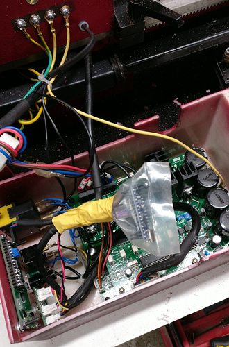
I also wrapped the board in a plastic bag before shoving everything in the enclosure.

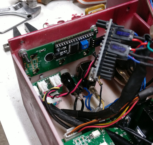
Cutting the window for the screen and putting the screws in the right place was quite a challenge because I could not move the enclosure to my mini-mill: it was to tall. I cut the window freehand with a Dremel tool. The following image shows the back of the LCD screen mounted on the top surface of the enclosure. It takes the location of the green power light, the yellow fault light, and the LCD socket.

One can hardly see in the previous image the green power light that was moved below the forward/reverse switch and the main fuse. Desoldering the green power light and resoldering the wires after the move was also tricky as the other end of the wires is connected to other wires, thus preventing the soldering operation to be performed conveniently: one as to do it within the enclosure. I later noticed that I cut the window for the LCD screen slightly too close to the opening
(i.e. too close to the spindle). When mounting the enclosure back to the headstock, it almost
touches it.
As is, it works, thanks a lot to
@Jenny for sharing this, it helped me tremendously.

For my training, though, I think I will continue to investigate the software changes I wanted to make initially, perhaps using a more powerful board. I purchased the nano boards from China using Ali Express marketplace. The boards costed only 2€ each (maybe this is the reason the boards cannot keep up…). I will try with other boards I purchased from Mouser the ESP32 pico Kit
<https://www.mouser.fr/_/?Keyword=ESP32-PICO-KIT>. The provider is more reliable and the ESP32 is far more beefy, probably even overkill for this application. The cost also remains very reasonable (8.73€). Programming is quite different from Arduino, so I will have to change a lot of things.


![DreamPlan Home Design and Landscaping Software Free for Windows [PC Download]](https://m.media-amazon.com/images/I/51kvZH2dVLL._SL500_.jpg)


