Another Webster

Home Model Engine Machinist Forum

Help Support Home Model Engine Machinist Forum:

This site may earn a commission from merchant affiliate links, including eBay, Amazon, and others.

black85vette

Well-Known Member
Joined
Jan 18, 2009
Messages
1,084
Reaction score
25
The other night I fixed our clothing dryer. As some of you will verify, fixing a household appliance WITHOUT being asked earns you "shop credits" which can be redeemed for extra time in the shop building engines. ;D

Being inspired by Longboy and then Brian's builds I headed to the metal store and got the materials for the frame. Already ordered some 12L14 for the cylinder and have it on hand. The flywheel is a recycled cast wheel from a railroad model engine. I have already turned it on the lathe to remove the flange and made the outside of the wheel flat. I am going to move everything on the frame up .25" because the wheel is 4" and I don't want to turn it down.

Did not take long to make my first mistake. If I had reread Brian's post about the frame I would have noted that the base was .375 and the vertical parts .3125. I already cut all the parts from .375 stock and have decided to just go with it and make the necessary adjustments. :Doh: So for now, three parts started and two of them are already wrong.

I don't build as fast as Brian and may have some delays so don't expect this to be quick.

IMG_2287.jpg
 
......All right Blk-Vette, I'm proud of you! ;D You can call yours the Webster Heavy Duty with that big frame and flywheel. Whats that wheel weigh? Looks over 4 lbs! Take your time on it, hobbies are not production work. Sometimes I just stared :-\ at my parts for 20 minutes before moving/ removing metal. Dave.
 
Yep know what you mean by "shop credits". Use them up quickly though as they can expire real fast! Good luck with your new build.

Nick
 
Got the frames mounted. I first drilling an reamed the holes for the shaft. I like to stack my frame parts and bore them together to keep the holes lined up and square with each other. May not be the preferred way but it seems to work for me.

The base is a temporary piece from the scrap box. I am not using the flywheel specified and may need to move the frame over a bit. Until I know for sure I will wait on the permanent base.

I drilled and tapped the holes in the mill. I drill a hole and then put the tap in the drill chuck to get it started. This keeps the tap lined up perfectly on the hole. Then I release it from the chuck and finish with a tap handle. When working in aluminum I pull the tap out when it starts to feel tight. Then clean it off and put it in to cut some more. On this project I positioned my holes after locating the edge of the work piece then used the X-Y table to locate my holes rather than measure, scribe and punch.

I made the brass bushings for the frame and a temporary one for the flywheel. I need to mount the flywheel and figure out how to get the gears fit in there. Also need to decide on how to pin the flywheel to the shaft. I am thinking that since I need a bushing I will extend the hub out as part of the bushing so I can drill it while separated from the flywheel.

Don't know for sure but think the gears will be next. This will be my first project to actually use gears I have machined. Not sure how long this step will take.

IMG_2290.jpg


IMG_2291.jpg


IMG_2293.jpg
 
I think its just great that you are building a Webster!!! The Webster is the first engine I ever built using gears too. As far as drilling the flywheel and crankshaft goes---Its very easy and works well---However--Be aware that there is a bit of a trick involved with the gear which attaches to the cavity in one side of the flywheel hub!!! When you get everything together and ready to drill, you will find that the hole drilled on the side of the flywheel where the gear is will ALSO pass through the hub of the gear. I covered that in my build---You might want to give that part a close look. Like you, I started out thinking, Ah Heck---I'll just use 3/8" plate for the sideframes, because thats what I had on hand. Then as I got farther into it, I seen that a ton of changes would arise out of not using 5/16" plate like the plans call for. The plans are "spot on" if you follow them to the letter, but if you make even a slight change at the beginning, it cascades as you get deeper into the build. Best of luck---I look foreward to following your build.
 
black85vette said:
I like to stack my frame parts and bore them together to keep the holes lined up and square with each other. May not be the preferred way but it seems to work for me.

That way usually works just fine, Vette. As long as you put the mounting holes where you wanted them, should be good.
The flywheel looks nice and hefty. It ought to make for a smooth running engine.

Glad to hear you're going to cut your gears. Do you plan on using the hobbing method you tried out a while back?

Dean
 
Brian Rupnow said:
The plans are "spot on" if you follow them to the letter,

Can't remember ever following a set of plans to the letter. :big: Always seem to make a modification or unintentional error. It is really nice to have your build to go back and read and see what gotcha is lurking just around the corner.

Deanofid said:
Glad to hear you're going to cut your gears. Do you plan on using the hobbing method you tried out a while back? Dean

Dean; yes I am going to use the hob I made back when that thread was going on. I was kind of thinking ahead to this build and wanted to build something that I could make gears for. This should not be too hard since the gears are just running a cam and valve. It does not have high torque or critical clearances. Since this is not done often I will try to cover the process in the posts.
 
I'll be watching, Vette. Although I've cut a bunch of gears, have never done one with a hob. I need to make a couple of those things and see if the gears come out to match some of the ones I've done with regular cutters. Show us the stuff!

Dean
 
Got the first gear cut. Decided to put a .25" shoulder on it so I would have a place for a set screw. This gear is 24 tooth, .812 diameter, 32 pitch and .25 inch across the gear teeth. By adding the set screw I get some ability to adjust the position of the gear from side to side and gives me some other options for the flywheel.

I made a blank the proper diameter with the shoulder on it, drilled and bored the center .375", cut the teeth, drilled and tapped for the set screw and then parted off the finished gear. I will post some more of the pictures in my photo account. For now here are just a couple shots of making the first gear.

I did not bother with index plates for this gear. A 24 tooth is spaced at 15 degrees and my rotary table turns 5 degrees per turn of the crank, so stop every 3 turns and cut a tooth and then repeat. Pretty simple and quick. Now I will need to workout the position for the cam gear since I am not using the gears specified in the plans. My will be close but may be off a bit.


IMG_2301.jpg


IMG_2307.jpg


IMG_2311.jpg
 
I'd seen several references to a 'Webster' but wasn't sure what it was.
I took a tour of the internet...and it looks like an interesting build.
I'll enjoy watching your progress.

Besides...I'm hoping it'll keep you out of any more trouble. ;D
 
That one sure came out nice, Vette. Very nice. Looks just like a gear!

Do you know what a gear depthing tool is? If not, just say and I'll give a short description. It will help you get the exact spacing for your gears, no guess work, no errors.

Would be nice to see your relevant pics in your thread, for the sake of continuity.

Dean
 
Troutsqueezer said:
It's time for me to explore making gears for future builds when I'm taking a break from my current build. I'll start by a Google search on "hob" since I don't have a clue what that is. :)

Trout; you just reminded me that I intended to include a link to the original post about gear hobs that got me interested in that method. It has a bunch of good information and links to other sites about the process including a series of videos on You-Tube.

http://www.homemodelenginemachinist.com/index.php?topic=7674.0

The advantage I found with a hob is that once you make one for a specific pitch you can use it for ANY tooth count. The issue with most other types of cutters is that they are only good for a single or small range of tooth counts. The drawback is that the shape of the tooth is approximated by several angled cuts. On the other hand it is close enough for light duty model building.
 
Dean; I don't know anything about a gear depthing tool. Go ahead and post about it.

I will add the rest of the photos about the gears to this thread with some notes:


4573359412_08fd0c40b7.jpg


Make the gear with the proper diameter for the teeth. This is .812" for a 32 pitch 24 tooth gear. To the right of the gear area is the shoulder where the set screw will go. To the left of the gear area is just cut down so the hob does not do unnecessary cutting beyond the gear.


4572725311_f6303fc184.jpg


Cutter height is set so that the center notch lines up with the center of the material. Then you move the material into the cutter the amount of the total depth of the gear tooth. This is just slightly more than the working depth.


4573359278_ef19966d60.jpg


Each pass is made and the shape of the gear teeth is created by 3 separate cuts as it rotates through each position. For this 24 tooth gear it is 15 degrees per tooth. 3 turns of the crank on my rotary table.


4572725481_99cc391f5a.jpg


Drill then ream the hole for the size shaft it will be on.


4573359454_7d86c6614f.jpg


Use an edge finder on the work and then position the gear so that the set screw will be centered and square to the shaft.


4572725617_05f4c0b863.jpg


Drill the hole the proper size for the tap. Then swap the tap for the drill bit in the chuck. Keeps everything lined up and makes a perfect tap.


4573359584_9dbb440143.jpg


Keep the gear attached to the parent piece until all the machine work is finished. Then part it off.


4572725709_5211f206de.jpg


Here the gear is on the shaft and ready to start on the cam gear.


First Vette, thanks for putting up the extra gear cutting pics. They're so pertinent to the build, and there
are often questions on the forum about it.

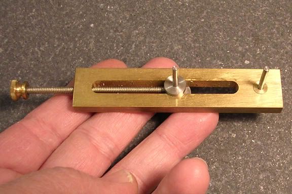
The depthing tool is an adjustable jig that holds the two gears so you can mark out the spacing. Easy to
make.


1depth.jpg


This is the top side, and you put one gear on the end post, and one on the adjustable post. This one is
for very small gears, but it would work for your gears. The posts are small, and the idea is, a gear of
any bore size will fit on them using a simple round bushing. The posts slide in and out of the tool, in
case you need longer or shorter ones. They're a close slip fit.


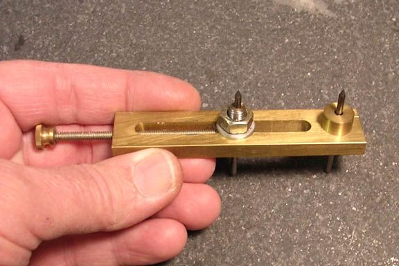
2depth.jpg


This shows the bottom side, which is the business end. The two posts are pointed, so when you locate
the position for the first gear, or a position of an existing gear shaft, like you already have on your
engine, the post on the end is put in the center of that hole, and the other post tapped with a plastic
mallet to mark the spot for the gear with the unknown position, which would be your ignition gear, in
this case.

The long threaded piece moves the middle post, pushing the gear that is mounted on it toward the gear
on the stationary post. When you have the two gears meshing nicely, no binding, no excess slop, that
post is tightened down with the nut, holding it fast so you can do your punch mark.

You can spin your gears while they are on the depthing tool to be sure they are meshing well before
you punch your mark(s).


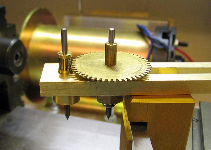
23depthingplate.jpg


This is a shot of it in use, just to give you a better idea.

For your use, since you have the hole drilled for the crankshaft, the fixed post just needs a bushing to
fit that hole. You can make the posts to fit your gear bore size, or use the bushings I mentioned earlier.

If you use one of these things, you can get the backlash on your gears perfect without any head
scratching, in case you have slightly off sized gears, or if the depth of cut for the teeth has minor
variations. By using a piece of paper of a known thickness, you can set the gear lash to what you like,
then locate the gear centers using the punch marks left by the tool.

Dean


Wow!! gents, this post is really becoming a mine of good info.

First a very easy explanation of gear cutting, then a dead easy way of getting the gear spacing correct. I think everyone could learn something here.

Nicely done.


Bogs
 
Yeah great info. Will have to remember where this one is.

Cheers,

Nick
 
Dean,

Thank you for the education.

Just when I think my learning curve is moving away from vertical, guys like you post a new lesson.

Thanks for sharing.

SAM
 

Latest posts

Back
Top