Another screw cutting question

Home Model Engine Machinist Forum

Help Support Home Model Engine Machinist Forum:

This site may earn a commission from merchant affiliate links, including eBay, Amazon, and others.

firebird

Well-Known Member
Joined
Oct 26, 2007
Messages
1,143
Reaction score
8
Hi

I have a Myford lathe, imperial, with a set of imperial gears. I am going to screw cut a fine thread 28-32 TPi thereabouts onto a bit of 24mm bar, I'm ok with cutting external threads now. The fact the bar is 24mm is irrelevant I think as I will be making the female part, IE the nut, to suit. My question is what size do I make the hole in the nut?? Is there a chart I can refer to or is there a formula. I'm thinking the hole size will be 24mm less twice the depth of the thread??

Cheers

Rich
 
Hello Rich,

Is this a 60 degree thread form?

If so, the following formulae apply:

Internal Depth of Thread = .541/N (N = No. of TPI [Threads Per Inch])

Internal Minor Diameter = Major Dia. (D) - 2(Internal D.O.T.) or D - 2(.541/N)
Note: This is used for single point threading (100% Thread Depth), Not Tap Drill Size.

Depth of Cut @ 30 degrees = .625/ N (N = No. of TPI)
Depth of Cut @ 29 degrees = .619/ N
Note: Compound rest swung 30 or 29 degrees to the left or toward headstock

Width of Flat @ Root of Nut = P/8 (P = Pitch of Thread = 1/N) [Flat on tool tip.]
Width of Flat @ Crest of Nut = P/4 [Resultant flat @ Minor Diameter]

Hope this helps.

Regards,
Mike
 
Hello Rich,

I have attached a few pages out of my notebook that may be useful. They include a diagram for lathe set-up and the relationship between Depth of Thread (DOT) and Depth of Cut (DOC). This may be helpful if your thread angle is different than 60 degrees (55 degrees or 47.5 degrees). Hope this helps.

Regards,
Mike

View attachment 60 Degree Internal Threading Notes.pdf
 
Hello again,

I have attached several handouts that I made up for my students when I introduced the topic of single point threading on the lathe. There are diagrams that illustrate the lathe set-up for both external and internal right-hand screwcutting on the lathe as well as the formulas for American National 60 Degree Threads which are most often used for toolmaking, maintenance and repair and for general shop use in the USA. These are also most commonly used in the home shop. I hope these will help someone give single point threading a try, it is a skill that needs to be developed and practiced like most other skills that require hand and eye coordination, but once learned opens up many possibilities in your workshop.

Regards,
Mike

View attachment Screw Thread Nomenclature.pdf

View attachment American National Thread Formulae 1.pdf

View attachment American National Thread Formulae 2.pdf
 
Hi

Mike I've printed out all your stuff and will sit and study it at the weekend, many thanks.

Tom, that's a very useful little programme, many thanks.

Cheers

Rich
 
Hello again,

I should mention that these formulas are all based on having the proper flat on the nose of the tool. In the case of a 60 degree thread of the American National thread form, this Width of Flat (W) = Pitch (P) / 8, Where P = 1/ N (Number of Threads Per Inch) or W = P/8

The numbers work out very well if the flat is correct. Almost never would you use a Sharp Vee Thread due to the potential stress riser created and the very fragile tool point. Obviously, if you touch off with a sharp pointed tool and travel the indicated DOC (Depth of Cut) in the formula, the thread will not be deep enough (oversize).

When single pointing threads, you are controlling the size or fit at the Pitch Diameter. For external threads, this is measured in commercial shops with a thread pitch micrometer or with thread wires or lacking these for a one-off, the mating part. For internal threads, if a commercial gage isn't available, you can make your own measuring the pitch diameter with thread wires or again for a one-off, use the mating part. The formula sheets I attached to the previous posts all provide the Basic Diameters. It is possible to calculate the limits of the tolerance, but much easier to look them up in Machinery's Handbook or similar reference tables.

I have attached a general drawing of a 60 degree external threading tool to illustrate the flat on the tool nose. For internal threading tools, you will generally need more clearance based on the minor diameter. The smaller the hole, the larger the relief required. This is a balancing act to provide enough relief so the tool's flanks will not rub and not so much as to weaken the tool. Side relief for internal screwcutting tools is often radial, rather than angular as in the drawing of the external tool.

Regards,
Mike

View attachment 60 Deg Ext Thrd Tool.pdf
 
The other way to tackle this question is to use the metric approach, eg if you were making a 24mm x 1.5mm pitch nut, the required drill size would be 24 - 1.5 = 22.5mm.

If you settle on say 32tpi for your project, that is a pitch of .794mm, so the drill size will be 24 - .794 = 23.206mm or .914 inch
 
Hello Rich,

In your first post you mentioned that the pitch of your thread was to be 28 -32 threads per inch on a 24 mm diameter bar. You didn't mention what the exact thread form was, so in case it is ISO Metric, I have attached a set of formulas for this thread form. I also have a Myford lathe, but haven't purchased the set of Metric threading gears and quadrant for it yet. I have a set for my 9" South Bend and that is what I have used when Metric threads come up.

If you have any questions or if I can be of any help, please ask. I have thoroughly enjoyed reading all of your project posts and have learned a great deal.

Regards,
Mike

View attachment ISO Metric Thread Formulae.pdf
 
Hi

Thank you Mike & bob

Here's another question. I have a good stock of triangular TCT bits. Can I use those to cut 60 degree threads? or are thread cutting tips a special form. I could soon knock up a couple of holders for them.

Cheers

Rich
 
Hello Rich,

I imagine that you could make a holder for your inserts that would work for some external threading applications. However, I think it would be difficult to use them on a shop made holder for internal threading. The difficulty will be in achieving the proper clearance or relief without modifying (grinding) the insert. Also, depending upon the size of the insert circle, you may be limited on how close you could thread up to a shoulder. Your threads would also have a radiused root, which isn't a problem as that is what the Unified Thread Form utilizes, but the numbers from the formulas are out the window. You would basically be cutting every thread by the seat of your pants, without any reference. Just use the mating part to check the fit by making the male thread first and using it to check the internal thread. If you can measure the external thread with wires, you can calculate the pitch diameter and control the size, in effect making your part the gage.

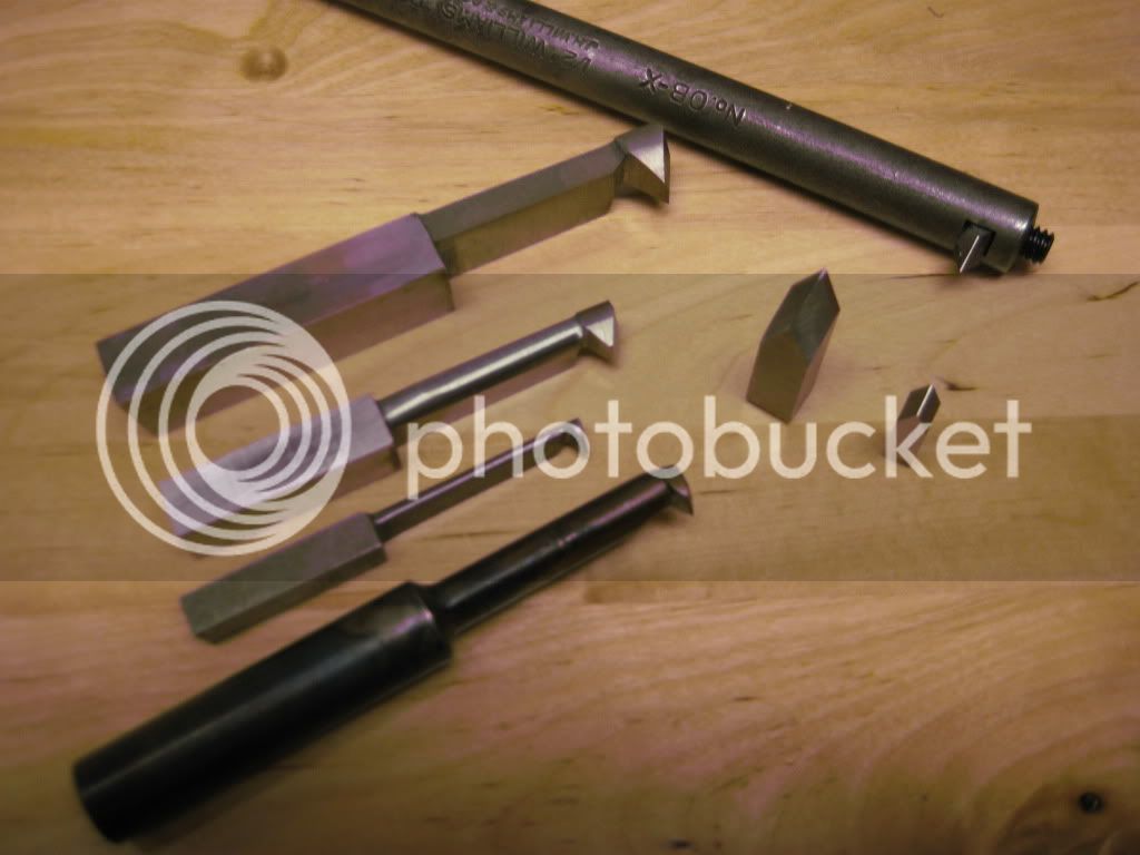
Your best bet is to grind some threading tools from High Speed Steel (HSS). For your Myford, a 5/16" square blank would be a good choice for your external bit and if you don't have a boring bar with the ability to use a smaller HSS bit, you could grind one out of a new 3/8" or larger blank. I took some photos of some of my threading tools for reference.

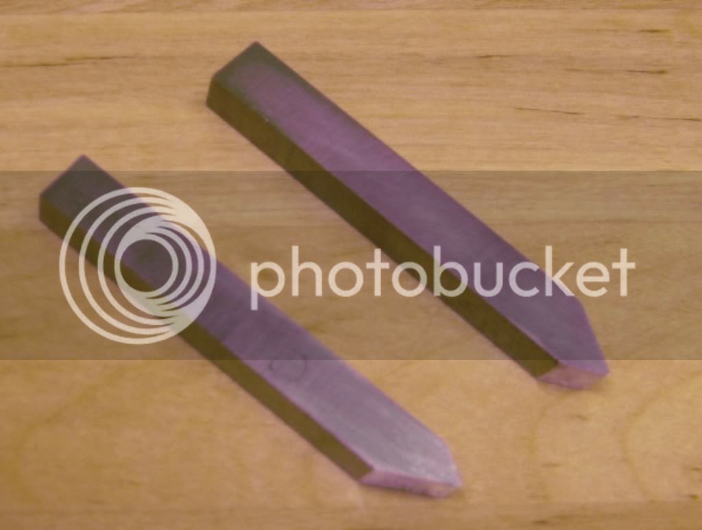
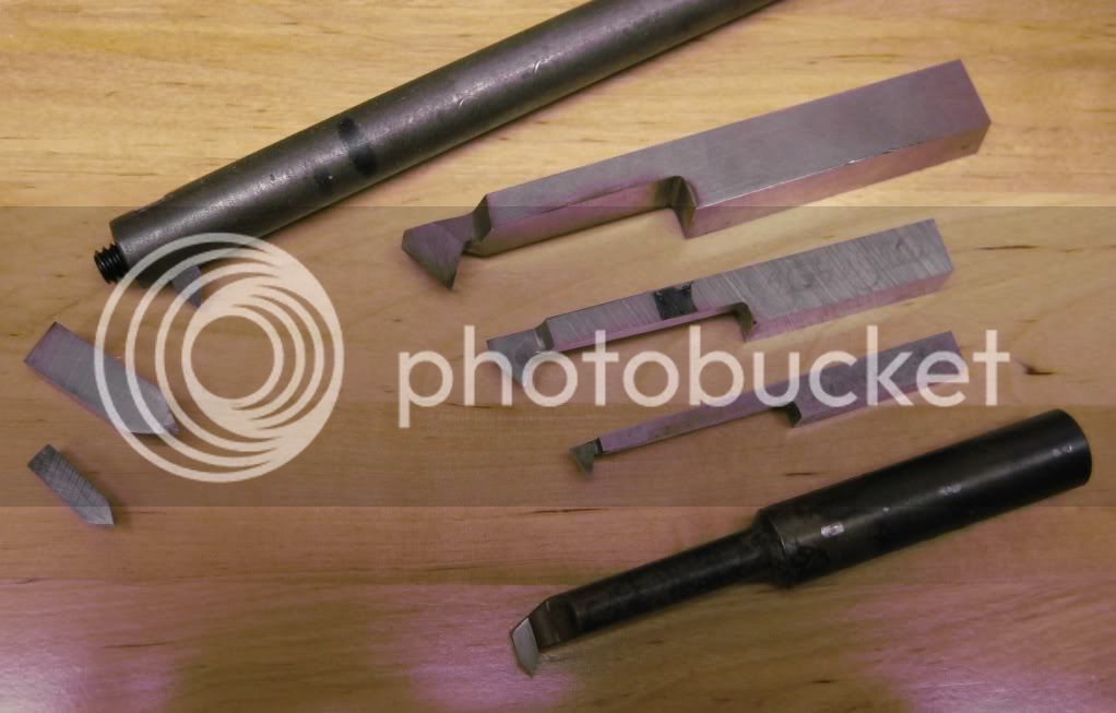
The first shows a pair of 5/16" square external threading tools that I use on my Myford. These have the point offset 1/8" from the leading edge and the one on top is for RH threading toward the headstock and the one on the bottom is for LH threading toward the tailstock.

ThreadingTools006.jpg


Another view.
ThreadingTools005.jpg


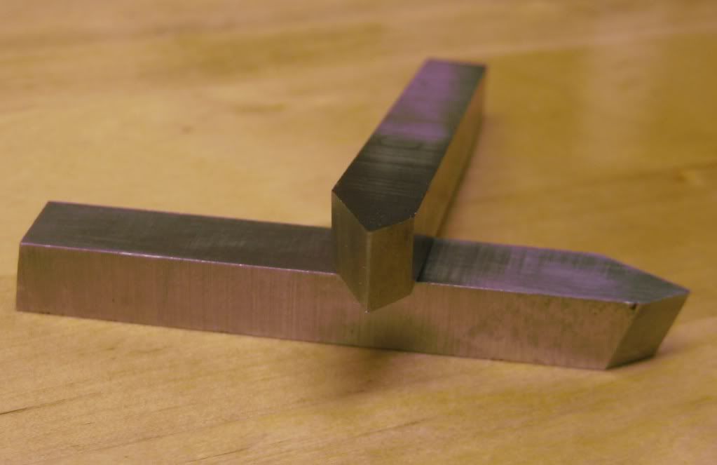
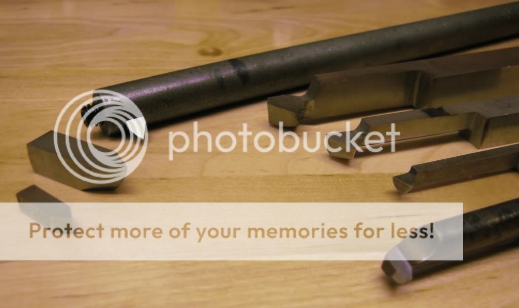
Next one illustrates the relief angles and the flat.
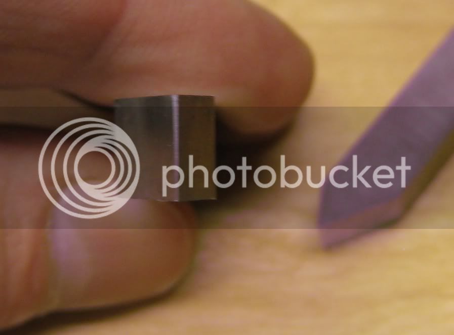
ThreadingTools007.jpg


Flat closer view.
ThreadingTools008.jpg


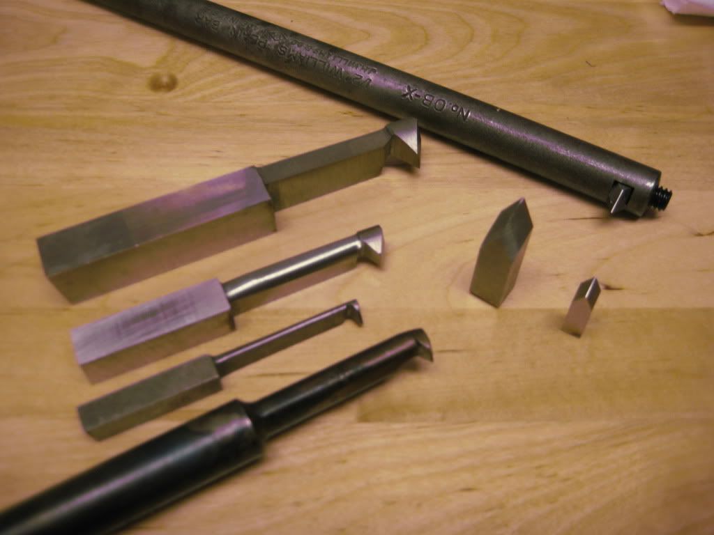
Internal Threading tools.
Bottom view
ThreadingTools004.jpg

Bottom view.
ThreadingTools003.jpg

Top view.
ThreadingTools002.jpg

Top view.
ThreadingTools001.jpg


The round shank tool on the bottom that is discolored was made out of drill rod or silver steel and then heat treated in the shop. It was made to thread up to a shoulder in a blind hole. I roughed it out in the lathe by eccentric turning in a four-jaw chuck and finished it by milling and finally filing prior to heat treatment. It worked great and I have used this technique for making several other threading and grooving tools. Works great for ACME threading tools. As long as you remember it is plain carbon tool steel and use the appropriate cutting speed, they hold up well.

I found out taking pictures of HSS tools is not easy. I hope you can see some of the detail.

I am pushing my luck here as far as timing out, so look these over and maybe it will give you some ideas.

Regards,
Mike
 
Hi MIke

A picture is worth a thousand words, many thanks.

Cheers

Rich
 
firebird said:
Here's another question. I have a good stock of triangular TCT bits. Can I use those to cut 60 degree threads? or are thread cutting tips a special form. I could soon knock up a couple of holders for them.
Rich

The point radius is way to large for a threading tool. The relief angle is too small, The edges are honed not sharp. Nope, not a good idea to use those laydown turning bits. There are carbide threading bits that work great, partial profile, full profile, on edge type. For general use the on edge type type is the best, full profile is pitch specific, so a set is needed to cut the usual sizes. More $$$ and generaly negative rake, which would not suit a Myford. With my bad eyes I use solid carbide pre-ground bits for my threading, as I'm unable to grind my own.

 
Hi Mike

I copied all the thread documents and looked true them. Read them back and forth. Ben cutting threads on the lathe for a wail.
On thing I never figured out
Why is the Pitch Diam. always in there?
It seems to me that all the other measurements could be taken from the Minor and Major Diameters. What is it used for?
I am not demeaning your prints I mean in general, it always comes up. In all the thread discussions and so. I must be missing something because I just don't get it.
Hilmar
 
Hello Hilmar,

The Basic Pitch Diameter is an imaginary cylinder which passes through the thread at a point halfway between the crest and root. It is equal to the Major Diameter of the thread minus a single thread depth. It is the principle bearing point of the thread. Tolerances and allowances are applied to the Basic Pitch Diameter to enable interchangeable parts and to determine the various classes of fit.

I understand that in making one-off parts like we do in modelmaking, some will think that talking about pitch diameter is a waste of time. For 99% of the threads that most machinists are asked to turn on a manual engine lathe or program on a CNC turning or machining center, you can just look up the high and low limits for the class of fit required in Machinery's Handbook or a similar reference book. However, there are times when a thread comes along that isn't a standard size and you can't just look it up. At those times if you are equipped with the formulas and the knowledge you can get your tail out of a crack and look like a star in the eyes of your employer. I was taught these same formulas in school almost 25 years ago now and they have served me well, so I pass them on to my students.

As a machinist and toolmaker, they have come in handy many times over the years. One shop that I worked in did work for Leica or the old American Optical Company. There were a number of times that the thread on the print was a special one that was not in the handbooks and the 10 or 1000 parts that were to be made had to be to print. The production machinist and QC department needed tolerances to work to and it was a simple matter to just plug the numbers into the formulas and have the limits that everyone needed to make sure the parts were to print and we were going to get paid for our work. If anyone is interested, I can attach the formulas for calculating the tolerances for the American National and Unified Thread series.

In a job type machine shop you just never know what is going to come through the door. I prefer to have the numbers to work to because it saves time and makes my life easier. Like they say, "Knowledge is power". This piece of knowledge got me a raise the first time this came up in that shop.

Hope this will help someone else.

Regards,
Mike
 
Hi

Thanks again for all the info Mike

Tonight I just couldn't resist 'having a go'. I have a pair of thread cutting tools, internal and external @ 55°. I cut a piece of steel to 24mm and cut the external 32tpi thread.


Then bored a piece of steel to .914 inch and cut the internal thread.


What do you know they screw together woohoo1 woohoo1


Cheers

Rich
 
Hi Rich,

Nice one.

A few suggestions that can make single point threading on the lathe a bit easier:

When you are preparing your work for single point threading, it is good machining practice to turn a chamfer on the external thread's major diameter @ 45 degrees to just under the minor diameter. This will get rid of that sharp corner which will throw up a nice big burr and will help to ease the threading tool into the work. Same goes for the internal thread, just turn a 45 degree chamfer so that the large diameter is slightly over the major diameter. This will minimize the burr generated after each pass which will now just need a quick pass with a fine file to remove before you check the fit with the mating part. The burr can be deceptive and cause the mating part to not even start onto the part even though the thread may be undersize. This is a common mistake my students would make.

The other area that can cause trouble is a huge dig-in at the end of the thread if you pull the tool out too late. In this case, the tool runs into the full depth of cut that has been fed in so far and this can cause the tool point to break off or the tool to shift in the holder, which usually results in the thread being wiped out on the next pass due to loss of synchronization. If your design will permit it, you can machine a thread run-out groove at the termination point. This type of groove is necessary on blind holes when internal threading and for external left-hand threads where the tool starts on the left and feeds toward the tailstock. The minimum dimensions of the groove are 1 to 1-1/2 times the thread pitch for width and to the minor diameter for the depth.

A spindle driving handle is a wonderful tool to have for precise control of the spindle when threading and works great for form tools and other operations that tend to produce chatter like finishing a large radius on a small light weight lathe like the Myford. There is a drawing for one for the Myford lathe in George Thomas' "The Model Engineers Workshop Manual".


Great start so far. The more you practice, the easier single point threading will become until it is just another routine lathe operation.

Kind regards,
Mike
 
Hi Mike

Thanks for the tips, they are duly noted.

cheers

Rich
 
Back
Top