Aluminum sand casting for Chenery Gnome Rotary

Home Model Engine Machinist Forum

Help Support Home Model Engine Machinist Forum:

This site may earn a commission from merchant affiliate links, including eBay, Amazon, and others.
I don't have an expertise in threading holes like that, but I can say that 356 aluminum that has gone through the 2-step T-6 tempering process is much harder and easier to drill/tap without loading up the bit.
Hopefully you can work out a solution.
.
 
I don't have an expertise in threading holes like that, but I can say that 356 aluminum that has gone through the 2-step T-6 tempering process is much harder and easier to drill/tap without loading up the bit.
Hopefully you can work out a solution.
.
Thank you Twin
 
If you can sort out your rubbing threading tool then I would cut that one oversize, not really critical what the diameter is as the mating cylinder sleeve will have to be single poinyt cut to match, just thread until you have a full depth form. If the thread has cut out of line with the hole then it will also not be true to the top face of the boss so you are not going to get a good fixing as it is.

Regarding the liner threads, using a die is not going to get you close to the shoulder ( no big undercut like the crankcase end) so it would be better to single point them to the sizes given on the drawings as going larger will affect the fin depth on the cylinder and will probably need the lower part of the cylinder increasing in diameter to accommodate the larger thread if you use that. Again a tap won't get you close enough to the shoulder inside the cylinder so it needs single pointing.

When it comes to the bottom end of the liner I would still suggest you single point it to say 80% thread depth and then run your die down it to get the final profile. This will ensure the thread is concentric and square to the liner. A thread that size in a tailstock die holder or worse a handheld diestock is unlikely to cut 100% true.

This is a cylinder that has been turned, bored and threaded all at one setting so everything is true and concentric and is the best way to get an accurate part which should lead to a running engine.


15b4926b-53de-4771-b371-3be286820821.jpg
 
If you can sort out your rubbing threading tool then I would cut that one oversize, not really critical what the diameter is as the mating cylinder sleeve will have to be single poinyt cut to match, just thread until you have a full depth form. If the thread has cut out of line with the hole then it will also not be true to the top face of the boss so you are not going to get a good fixing as it is.

Regarding the liner threads, using a die is not going to get you close to the shoulder ( no big undercut like the crankcase end) so it would be better to single point them to the sizes given on the drawings as going larger will affect the fin depth on the cylinder and will probably need the lower part of the cylinder increasing in diameter to accommodate the larger thread if you use that. Again a tap won't get you close enough to the shoulder inside the cylinder so it needs single pointing.

When it comes to the bottom end of the liner I would still suggest you single point it to say 80% thread depth and then run your die down it to get the final profile. This will ensure the thread is concentric and square to the liner. A thread that size in a tailstock die holder or worse a handheld diestock is unlikely to cut 100% true.

This is a cylinder that has been turned, bored and threaded all at one setting so everything is true and concentric and is the best way to get an accurate part which should lead to a running engine.


15b4926b-53de-4771-b371-3be286820821.jpg
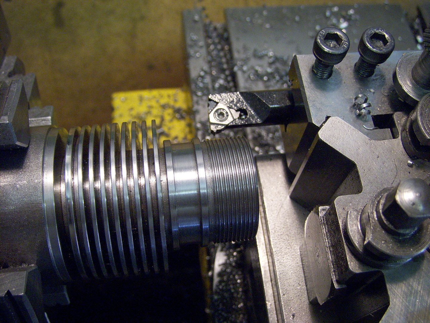
Thank you Jason. This is what I needed to know. Curious: in your photo, did you ‘single point’ thread here in Reverse? How many tpi is this? Looks extremely clean!
 
Yes I run the lathe in reverse which means you can go at several 100rpm and not have to react quickly to stop the feed. Best with a bolt on chuck rather than a screw on.

Pitch is 0.75mm x 21mm diameter so not far off your 32tpi. in free cutting steel.

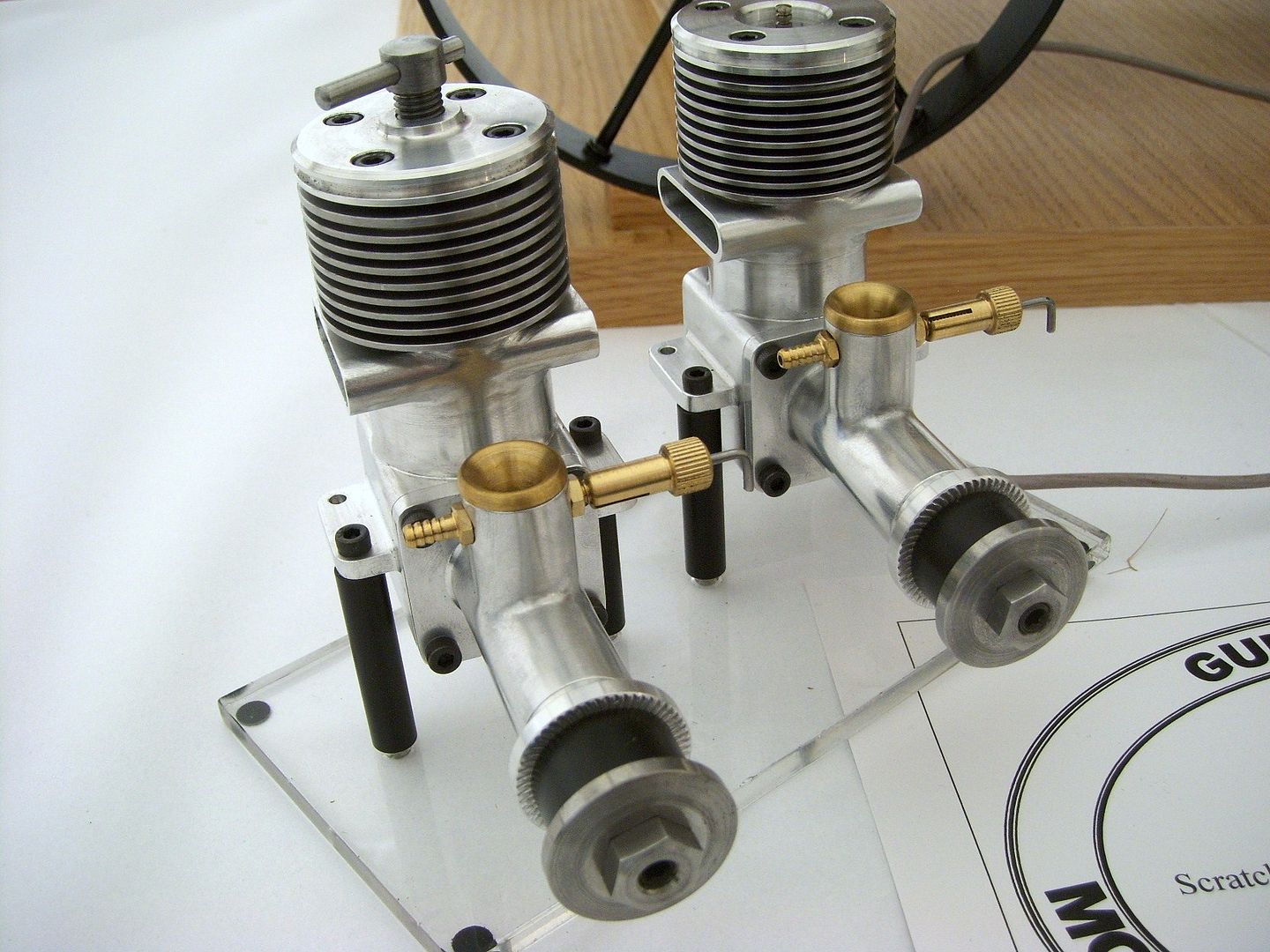
It's one of two engines Glow & diesel scaled up from 3.5cc drawings to 5cc, crankcases and front ends cut from solid, saves all that mucking about with castings :p

57ecdf50-d68e-4d3a-923a-d0c1f1cf9ce5.jpg
 
I finished machining the threaded cylinder bosses on my 1/5 scale Chenery, Gnome Mono Rotary engine, cast Aluminum crankcase. The threads are good and everything is true and concentric. This was accomplished using my second, back up casting. The first casting is a near perfect aluminum (shiny, no porosities), but not 100% true and two threaded bosses are deficient ( but can / will be re-threaded with a 1-1/16”- 28 Die). I am glad this is done as the casting has a limited availability.
Next I will start the steel cylinder liners need to somehow make these fit into these finished aluminum bosses…. Merry Christmas to everyone.
 

Attachments

  • IMG_9521.jpeg
    IMG_9521.jpeg
    1.8 MB
  • IMG_9520.jpeg
    IMG_9520.jpeg
    2 MB
I finished machining the threaded cylinder bosses on my 1/5 scale Chenery, Gnome Mono Rotary engine, cast Aluminum crankcase. The threads are good and everything is true and concentric. This was accomplished using my second, back up casting. The first casting is a near perfect aluminum (shiny, no porosities), but not 100% true and two threaded bosses are deficient ( but can / will be re-threaded with a 1-1/16”- 28 Die). I am glad this is done as the casting has a limited availability.
Next I will start the steel cylinder liners need to somehow make these fit into these finished aluminum bosses…. Merry Christmas to everyone.
Looking for advice on how to drill holes, 20, #57 intake holes perpendicular to the threads , on steel cyl. liners. I have a small Harbor Freight mini lathe (7” x 12”), and mini Mill machine and a large ( too large?) indexing head…. The holes would have to be close to perforating the threads; no? (The threads are not made yet…).
 

Attachments

  • IMG_9458.png
    IMG_9458.png
    4.8 MB
  • IMG_9316.png
    IMG_9316.png
    4.8 MB
  • IMG_9060.png
    IMG_9060.png
    3.6 MB
Looking for advice on how to drill holes, 20, #57 intake holes perpendicular to the threads , on steel cyl. liners. I have a small Harbor Freight mini lathe (7” x 12”), and mini Mill machine and a large ( too large?) indexing head…. The holes would have to be close to perforating the threads; no? (The threads are not made yet…).
 

Attachments

  • IMG_9574.png
    IMG_9574.png
    2 MB
My setup is a Myford dividing head on a Myford Super7 and setting the drill bit very carefully to just touch the outer diameter of the cylinder. Keeping everything rigid helps to keep the holes from breaking into the thread and to make sure you don’t break too many drill bits. I have made a special chuck which fits the Myford spindle and allows the cylinder to screw in head down so that the bottom end is presented to the drill correctly.
 
If your indexer is too big use it to make a fixture. One central hole and 20 around the edge. Mount on the mill so it can pivot around the central hole and have a way to index the 20 other holes then you can drill on the mill.

Or work out the co-ordinates for the 20 positions and just ctr up the part and drill using co-ordinates assuming you don't have a DRO that can do them for you.
Thank you. ‘Mount on the mill’ would be the trick. I might be able to mount the indexing table onto the Mill machine but there is currently no provision for mounting a chuck to grab the piece or a fixture. But I will go back to the Mill machine mindset… can’t wait to see these tiny, #57, drill bit(s), go through this steel…!
 
Thank you. ‘Mount on the mill’ would be the trick. I might be able to mount the indexing table onto the Mill machine but there is currently no provision for mounting a chuck to grab the piece or a fixture. But I will go back to the Mill machine mindset… can’t wait to see these tiny, #57, drill bit(s), go through this steel…!
Humm, thinking about it a bit more, if drilling the 20 holes from a counterclockwise rotation of the piece, I only need to rotate one spot to the left 18° and drill then repeat…
 
No.57 isn't tiny it's over a millimetre in diameter! Tiny drills are for really small holes, like tapping UNM 0.30 threads which uses a 0.0104 drill (0.26mm). Not a job I'd like to tackle though.
True; I’ve tapped 00-90 (Walthers brass), but not through 1/2” of steel. I still haven’t done this yet. I’ve been unable to get into my shop for a few days now. Maybe you blessing your disguise; I spend a decent amount of time thinking about the next couple of procedures, dealing with the steel cylinder sleeves, etc. Thank you for the help; I do need all the help I can get. I’ve kind of bit off more than I can chew but then again that’s my nature…
 

Latest posts

Back
Top