A Visit to Ford's First ("1893 Kitchen Sink Engine")

Home Model Engine Machinist Forum

Help Support Home Model Engine Machinist Forum:

This site may earn a commission from merchant affiliate links, including eBay, Amazon, and others.
An excellent write up indeed! However, and this is just my opinion based upon my observations regarding your photos, I believe Mr. Ford modified his original ignition system to make it a more consistent and reliable concept engine at a later date y adding a spark plug. The protuberance on the combustion chamber that you mention appears to be nothing more that a plugged hole, probably the original location for the make and break ignition. Its position would be more conducive to ignition in an after top dead center make and break.

Additionally, the pice you refer to as a gas igniter is indeed a spark plug of the 1915ish (?) vintage and appears (if my theorizing is correct) to have been added later to support that more reliable ignition and running with a buzz coil or something similar.

spark-plug-sale-1917.jpg


Additionally, the contact ground wire hitting the cam at just after tdc is a unique way to ensure that the ignition system is energized on a 4 to 1 ratio. Simplicity at its finest!

Another interesting point regarding the combustion chamber is the apparent offset of the intake versus exhaust ports. Once again, as Henry was a steam plant engineer, he understood the importance of valve timing in the cutoff principle, and with the intake port all but closed off by the forward movement of the piston in the exhaust stroke, there would be absolutely no exhaust pressure against the intake system, thereby ensuring that the waiting fuel charge would not be blown back out of the mixing chamber by the leakage of high temp gases at the swing valve.

Having never been in close proximity to the original engine, but after studying your exhaustive photographic records, that is just my two cents worth, and since I will probably never get the access you have had, I can draw no further conclusions than what I’ve included.

Thank you again for this excellent treatise on this valuable bit of engineering. I am considering a build of a replica myself, and I’ll most certainly use your very extensive volume of work as a backbone to my build!

John W
 
John W - great observations and comments!

Also - thanks for the picture; I was looking through old publications trying to find a picture of a spark plug but did not have any luck. Can you tell me where that picture came from?

The official drawing of the engine shows the contact igniter in the current position of the plug, but here are a couple of reasons why you might be right:
  • The drawing was created many years after the engine was built and contains at least one clear error (an incorrect length measurement). There may be other errors or inaccuracies.
  • We have no way of knowing whether all of the parts now on the engine are original, or whether some work was done to make it "presentable" for showing at state fairs and such.
Also, I got the impression while reviewing my photos that Ford may have made a few changes to the engine as he went along, to improve or fine tune the design. Your idea that he took the trouble to replace the original contact igniter with a spark plug is an intriguing one. I was under the impression (with absolutely no evidence to back it up!) that once Ford got the engine working, he more or less put it on the shelf and moved on to other things. On the other hand, if he wanted to use it to demonstrate his knowledge and abilities to other people, he may well have had good reason to make improvements. Or maybe he just wanted to learn more about ignition systems . . .

An alternative theory is that he took an off the shelf spark plug and modified it into a contact igniter.

On a related note, I found a reference on contact igniters which talks about the use of a "self-induction coil." This is basically just a wire coil on an iron rod, which would have been much easier to make than a buzz coil.

Also, take a look at this drawing (https://www.thehenryford.org/collections-and-research/digital-collections/artifact/361250) which shows the igniter farther back on the cylinder as you suggest, and no coil in the circuit.

It's fun to speculate on these issues, but I think it is also useful as well as your comment made me take a fresh look at the ignition drawing and notice a detail I had not paid attention to before.

I'll be updating my web page with the results of my research, and I will add to it if I come up with further information. Thanks again for taking the time to comment.

Interesting stuff for sure, and as you stated, the engine may have been improved and/or changed experimentally, or like the rest of us nuts, just for the simple enjoyment of watching one of our creations run!

I found the old ad on this website:

https://oldautonews.com/first-spark-plugs/

I very much enjoyed your work on this, and my conjecture is merely speculative, as Henry is no longer around to quiz on the subject, and it looks like he wrote very little about the construction of the original at the time of building. This leaves LOTS of holes for us reverse engineers to fill in.

Once again, thanks for all the hard work, and I look forward to any further additions in the future!

John W
 
One more thought and then I’ll leave you alone with your own thoughts. What if the combustion chamber were not made from an angle valve, but instead from a cast iron pressure relief valve? It would explain the adjustable nut and stem on top, and if tightened to the max, would provide enough resistance against this low compression engine, while reducing the combustion chamber size, or at the very least, allowing for an adjustment to the compression ratio.

I found a picture of a similar looking antique pressure relief valve, and it looks remarkably similar. Unfortunately, I am unable to link to the picture or paste it here.

John W
 
JS sent me an email with some interesting comments, which he has given me permission to share here:

Great write up on your visit and the engine. In looking at your photos in more detail, there is a gap between the ground spring and the cam. The Ford archives ignition sequence drawing shows the following:
  1. Piston electrode contacts ignition plug, spring not contacting cam
  2. Piston electrode contact overtravels ignition plug opening circuit, spring contacts cam.
  3. Piston electrode contacts ignition plug and spring in contact with cam. This produces a momentary short circuit.
  4. Piston electrode breaks contact with ignition plug drawing a spark.
  5. (Not shown on drawing) Spring breaks contact with cam giving a double break to the circuit ensuring spark goes out.
This is consistent with my knowledge of DC applications. I’m a retired electrical engineer who worked for Westinghouse and have experience with industrial DC systems. It can be difficult to break a DC arc. It is common to use two breaks in order to do so. It is much easier to interrupt an AC arc since it does so 120 times a second without any external help.

This system is very crude and timing is critical. The Ford archives drawing shows a cutaway of the piston in the cylinder. The cutaway shows a 90-degree bent electrode that will contact the ignition plug. The piston electrode, ignition plug electrode, or both would need to be flexible. Otherwise, the adjustment of the wiping action would be extremely critical. It takes 30,000 volts to jump 1 cm at normal atmospheric temperature and pressure. A 110VDC potential needs a gap of less than .037 mm to arc under the same conditions. I doubt much of a change at the compression ratio this device has. I admire anyone who can get this original ignition system to work reliably. A spark plug and induction coil would be incredibly easier.
The drawing he was referring to is here:

I was grateful to JS for reminding me of that drawing, as he noted a detail I had completely missed: the circuit is broken twice, once at the cam and once at the plug. This completely explains why the ground is not just connected to the frame. However, if you look at the spring contact closely, you can see that one leg is above the cam, and the other leg is contacting the base of the frame. The second leg would have completed the circuit continuously; perhaps there was insulation under this originally, which has since been lost.
 
John W - great observations and comments!

Also - thanks for the picture; I was looking through old publications trying to find a picture of a spark plug but did not have any luck. Can you tell me where that picture came from?

The official drawing of the engine shows the contact igniter in the current position of the plug, but here are a couple of reasons why you might be right:
  • The drawing was created many years after the engine was built and contains at least one clear error (an incorrect length measurement). There may be other errors or inaccuracies.
  • We have no way of knowing whether all of the parts now on the engine are original, or whether some work was done to make it "presentable" for showing at state fairs and such.
Also, I got the impression while reviewing my photos that Ford may have made a few changes to the engine as he went along, to improve or fine tune the design. Your idea that he took the trouble to replace the original contact igniter with a spark plug is an intriguing one. I was under the impression (with absolutely no evidence to back it up!) that once Ford got the engine working, he more or less put it on the shelf and moved on to other things. On the other hand, if he wanted to use it to demonstrate his knowledge and abilities to other people, he may well have had good reason to make improvements. Or maybe he just wanted to learn more about ignition systems . . .

An alternative theory is that he took an off the shelf spark plug and modified it into a contact igniter.

On a related note, I found a reference on contact igniters which talks about the use of a "self-induction coil." This is basically just a wire coil on an iron rod, which would have been much easier to make than a buzz coil.

Also, take a look at this drawing (https://www.thehenryford.org/collections-and-research/digital-collections/artifact/361250) which shows the igniter farther back on the cylinder as you suggest, and no coil in the circuit.

It's fun to speculate on these issues, but I think it is also useful as well as your comment made me take a fresh look at the ignition drawing and notice a detail I had not paid attention to before.

I'll be updating my web page with the results of my research, and I will add to it if I come up with further information. Thanks again for taking the time to comment.

Well, thanks to your historical research, I’ve decided to build a copy of Henry's engine. I’ve purchased the plans set and parts from Mr. Ridenour and gathered the rest of the materials for the build. I have decided to deviate from Mr. Ridenour's plans in order to be more historically accurate thanks to your research and excellent photos.

Of course, finding parts from 1893 are pretty much out of the question, which is too bad because I believe I’ve determined how he may have fabricated his make and break ignition, but if I can get my proof of concept engine running, I will dive into attempting the pressure relief valve system he employed for his combustion chamber at a later date.

Thanks again for all the leg work on this. As I’m in Arizona, the Henry Ford Museum isn’t just around the corner, and even if it was, getting access to the engine at the level you received might be damn near impossible! I have visited the museum several times in the past while visiting my in-laws in Northeast Ohio, but as they are now deceased, I can think of better vacation locations!

I probably won’t document my build, but I promise to share links to pictures and video of the running engine when completed.

John W
 
John -

Good luck on your build, I look forward to hearing more about it.

Getting the plans from Leon Ridenour is a good start; I think he did a great job of adapting the original design to "modern" parts (which if you think about it is very much in the spirit of the original engine). I have had the pleasure of speaking with Mr. Ridenour over the phone, and he was also kind enough to send me some email comments recently (some of which I will share on my web site, with his permission).

I spent a few hours looking through old (circa 1900) catalogs online to see if I could find listings for the original parts, but without success. On the other hand,some parts like the globe valve are still available and made pretty much in the same way as the Ford parts. I really need to make a trip to the Detroit Public Library, which has a tremendous collection of early automotive documents.
From watching his dvd and seeing the personalized notes he’s included in his plans, I get the impression that he’s a damn nice guy that has a genuine desire to help with any problems that arise! I don’t want to publish my build simply because I’d have to make parts of his plans available, and that’d be a real slap in the face to a guy selling his knowledge and skills at a most reasonable price. My first iteration will follow his plans almost to the T (pun intended) so I can get a handle on the basics before moving forward.

Since that angle pressure relief valve appears to be in very short supply (composed of unobtanium I believe!), I am considering turning one from common materials and building internals to closely mimic what I believe Henry utilized in his make and break system. We shall see how well my guesstimation works out...

Anyway, I’ve finally gathered all the necessary materials with the exception of a large handwheel, and have completed the “carburetor” and intake system. Slow going as my workshop isn’t cooled and the summer heat here has been hovering right at 107 degrees Fahrenheit. On to the combustion chamber and cylinder!
 
I thought people interested in this post would also be interested in what I think is a very interesting discovery thanks to the sharp eyes of my acquaintance "WH." There is a photo in the book Ford Methods and Ford Shops which includes the Ford's first engine in the picture (taken 1914 at the Ford Highland Park plant?).

See comment 4 in this link for my thoughts on the picture, and a bit more background.

For more on the book (and a link to a free download) see this link.

Here's the photo for those who just want a quick look.

_0kPmqZvFidZYDxAHGbJXjNaI6j7Et0AbBVOPG7H4oRVpzbE9Zp0DIuzlSNGoKjdpxb2J6VqAir4-cXllijaFYNxBXZxI-3LL7HA-M3JP32Cyka0JcaoE9nzp0IPAF1QkoTZ6h1EFudhBMh1OfWJQgCRnGqAJ4N5zO40oj1xEd73M4NAyYotppwJRQwfu9WBou-Fek6RJBbRDiHli6ZRT0Z2pVNmJpHPeAOOMxIa0FxxntjoiycL7sOiC8ZpRWKui0RaC4DKa9Ocnkbl46zGzfGuq6egyOLSq2_EmjFr_XnC9bMbXlxWNxUqEgkpLOZudvZDBDfMGnwCQ4gal9JKGOW9cB6PXZoxEd_9SisK1AfABADIjS3b09MES3AFdOB7Hh2KnK9h_cwbKvz_ERtgnfi5_4EYPNF5801nPPg_hrmf_qWaLsqmTxfzkUz783v1Md8UGIqXZMhLGBxGBJwWJ5b7HsiVMaLTTPY_F7VgGLfcDWx06uBfG42OPJA-Y0oyMclup-vmK-uY_74KoHEJkY4AqMNZDtJjhJqlqzEvMwrYMkU0RBrrd88rIEaaPwP-a-YVdqNKC5A8vxGBZJGD4b8AdSRv-F8JIXKp2GsenkpaKMtD99ABZyvO6hk5-M8HvDRSsN6zn5NhTTonyQh_q6_YfVKFaa9BZrojBAsjTH609Qf4NbdJXrhy=w1122-h865-no
 
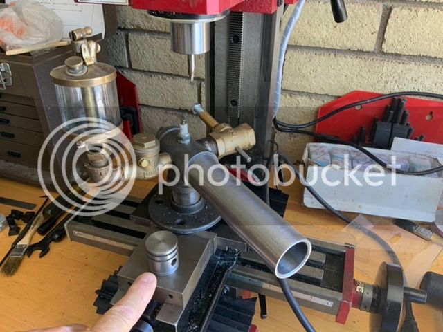
Here’s where I am in completing my Ridenour build. It’s been slow going doing the work on a mini mill, but slow and steady wins the race!

I put my finger in the picture as scale reference next to the piston.
A5661387-69A9-41FA-A11A-5E50C33AF227_zpsmbuv4z1x.jpeg.html
 
Does Ford's Kitchen Sink Engine have plans out there to follow and build one. I see a lot of people making one. Do we have to look at pictures and figure it out on our own? Or does someone have a blueprint sheet of how to build one? Are there plans for purchase somewhere?
Grasshopper
 

Latest posts

Back
Top