A V8 Maybe

Home Model Engine Machinist Forum

Help Support Home Model Engine Machinist Forum:

This site may earn a commission from merchant affiliate links, including eBay, Amazon, and others.
Hi, I couldn't respond any sooner having replace 4 computers putting the set up back in full working order was a bit of work.
Back to your card info as "gbritnell" says there is a few thing to take care of with these carb, but when all done properly they work like
a charm. the main thing is NEVER to use one with a Bubble (primer) these are garbage. As for the size of venturi size I dont think
it's an issu with what your building. If your planning to use the original carb pump all you need to do is use the positive pulse from your
crank case " were your burp tube goes " and that is more then enought. This pprincipal is beeing use on any 4 stroke using a fuel pump.
For the metering side "adjustement" to calibrate your spring tension on your fullcrum use a vacuum gauge, spin your motor over with your starter and register your vacum, ste the spring tention to this minimum value and your up and running. I did so many of these cards in lumber jack events and theyve all been sucess, you can run, nythro, methanol, in these with miner drilling. If you decide ti go this route, try finding the smallest one you can and that was use with read valve motor. The hole for the main jet is not locate at the same place in the venturi making it even better when use as a down draft carb. Hope this help, I'll try to find some pictures and post them

keep up the good work

Luc
 
HI Danny
That Mill is pretty much the same as mine Andy, so should do the job no worries :)
As you know, Im not an expert by any means and have only done half a dozen pours so far but am starting to get an idea on the simple paterns.
Im planing to pour the Valley cover on Sunday if you would like to join me? I Watched Bez do a few pours before I jumped in with the V8 Block;D

Pete

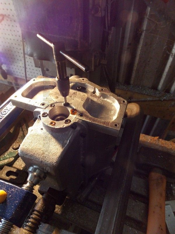
Yeah I liked the mill Pete, it lacks the power everything that yours has but mine has auto tapping which I thought was a nice touch ... ;D

I will eventually add a DRO and power feed (X-Axis) but it will have to do for now. :)

Sorry, no can do Sunday, I'm busy with chores ... dammit! I would have liked to see you pour and get some more details about your burner etc... I will try to get up there soon though.
 
Hi Pete,
The accelerator pump is just there for looks, along with the automatic choke housing. The needle valve is hidden underneath it.
I found the drawings for the carb. If you have some way of reading .dwg files I can send them to you. There's too much on one layer to send you a PDF file. It would get terribly confusing. As far as the distributor I don't have a completed drawing. I made sketches using the original distributor that had points in it and changed it over to a Hall effect type. I could send you the drawing that I supply with the prints for my 4 cylinder OHV engine. This would give you an idea of how it's built. You could add your own dimensions to it. All of my Hall distributors are built pretty much the same way. I have one fixed magnet mounted on an angular base inside the the distributor. The Hall is mounted to an aluminum plate on the outside. Inside there is a steel, and it has to be steel, disc which has windows in it. As it rotates the windows turn the magnetic field on and off to trigger the Hall sensor.
gbritnell

OHV distributor.jpg
 
Hi Luc
I notice that one of my collection has a much smaller venturi hole then the others although at at this time I don't have a pair and found 4 with the primer bulb which Ive striped and put in the pot ready to cast the valley cover.
No Worries Andy, give me a yell when your ready :)
Hi George
Yes please send both the Carby and Dizzy drawings, I'm very very keen to see how you have done both.
My Email is
[email protected]
or skype
metalmad11
I have never used the Hall effect type and am a little scared of them:hDe:
George, is that a mechanical advance I see hooked to the accelerator rod?
That I have To see!!
I have done a little more on the Valley cover today and will mount a flat plate on top to bolt on the Roots type Super charger if and when I get one made.
Pete
DSCN0414.jpg
 
Here have a look at this video and it should build faith in your project
[ame]http://www.youtube.com/watch?v=zIZudHqtEmY[/ame]

cheers
Luc:)
 
Thanks Luc
I have seen this before and the later videos are even better.
The one that started this project for me was a run with the blower that sent chills down my spine.
Its interesting to note the rocker gear on the Black widow seems to run on a rod and the rockers in what I have are stud mounted.
I can not account for the many differences and contradictions on my partial plan set, but The Blown Video had such a huge impact on me I had to try and make something of what I have. As a result my Engine is inspired by the Black Widow, yes but I simply don't have enough information to build that Engine and am just winging it and hoping it works :fan:
Pete
 
Hi Pete,
As far as the rockers go, over here GM was the first to go with individual rocker arms. Ford had rocker shafts up until the 260 V-8 around 1962. Although my 302 should have individual rocker arms to be prototypically correct I went with rocker shaft for lubrication. Individual rocker arms are lubricated by oil going through the hollow pushrods which would be almost impossible to recreate while the shaft can be fed by an oil line taken from an internal oil passage in the block. My engine has the same lubrication system as the full sized engine. It has a geared pump driven off of the distributor shaft which feeds oil to the filter, to the oil passages in the block and then through the crank to the rods. I originally tore the engine down several times for leaking head gaskets but never for oil related problems.
gbritnell

302 d.jpg


302 f.jpg
 
Hi George
Whenever I look at the factory like detail on your Engines im inspired even more.
I have so many exciting things to build on this project, I hardly know where to turn. Perhaps its not such a bad thing that there is so much missing from my plan set as its testing my limits a little.:fan:
I have so much to do its not funny, ive started work on a steel mold and core for the pistons and am ready to cast the manifold.
Your dizzy cap has given me an idea of turning up the cap in parts, drilling and then pressing in the 8 outside cyl wiring holders as incerts that id like to try, I just gotta find some plastic.
I also think I can adapt your dizzy to fit so thats another headache solved Thm:
The head gaskets I intend to trial thin lead sheeting.
Pete
DSCN0415.jpg
 
Delran is easy to work with for your distributor.
Why don't you use modeling clay for the mold .. woudnt that be easier?????
 
Hi Luc
I have a little left over from the Wallaby dizzy cap and that machined real nice, so if there is enough ill use that.
The piston mold I'm toying with is basically a bit of pipe with an internal taper, a 5 piece core sits inside that and my hope is that if I disassemble as soon as the alli freezes but before it cools, I maybe able to make easy and reliable internal piston shapes for example the internal boss etc.
The piston could then be put on a mandrel and the outside turned, if this is successful this mold would see service in many of my other engines as well.
I wish I had thought of this before as I melted 5 mini bike pistons to make my heads but would have preferred to save those for casting my own pistons rather then use for instance material from an old intake or head.
Pete
 
Hi Rob
Happy new Year!
 
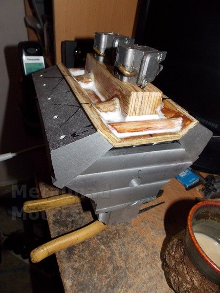
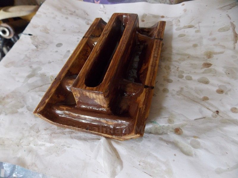
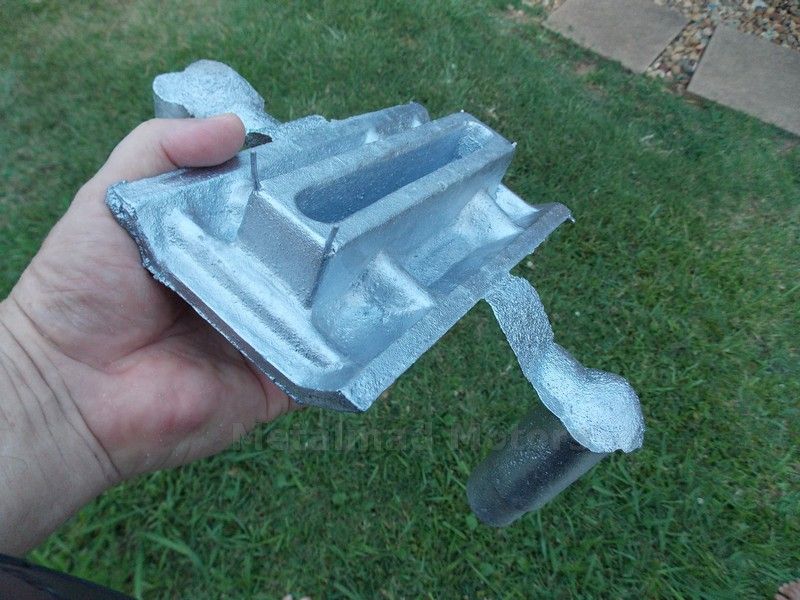
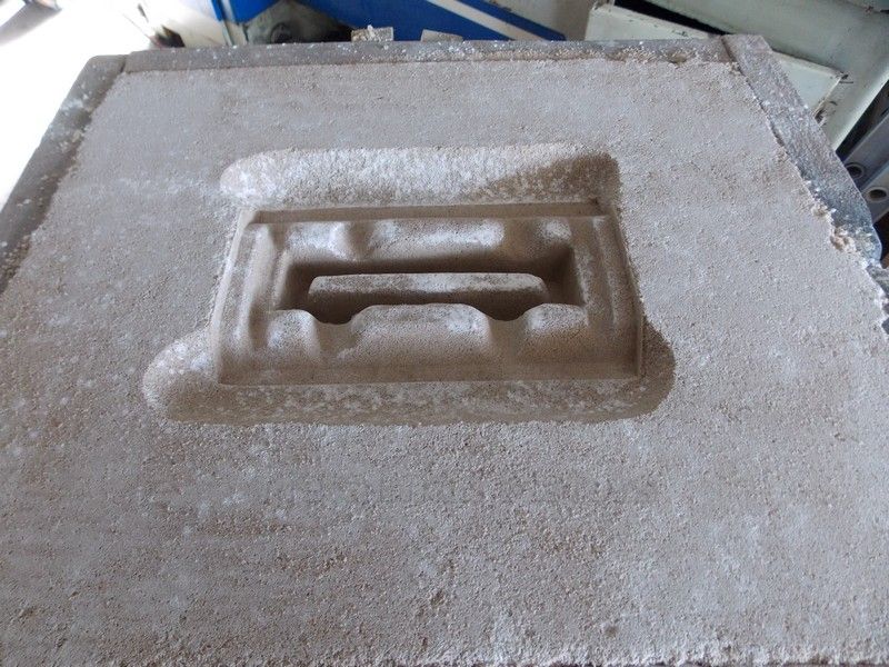
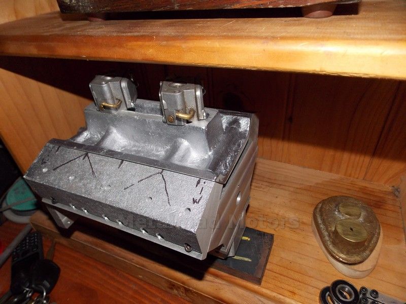
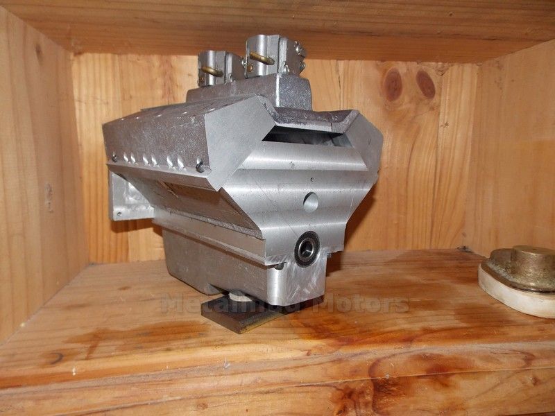
I had a bit of a fail today on my first attempt at the intake manifold,
I used a spoon to carve out the area under the sides of the manifold but did not leave any way for the metal to get into the mold, as soon as I started to pour I knew I had a mispour, The second attempt went very well indeed and I must say I surprised myself with how good it came out:D
Pete
DSCN0422.jpg


DSCN0419.jpg

DSCN0417.jpg
 
Heres a pic after a go on the linisher.
just for kicks!
Pete
DSCN0425.jpg
 
Hi Brian
Thanks buddy
A linisher is just a belt sander.
I picked up a second hand one and really use it a lot now making my patterns as well as cleaning flashing of castings etc, mine has a disc on the side as well as the belt and I wonder how I ever got on without it ;D
Pete
 
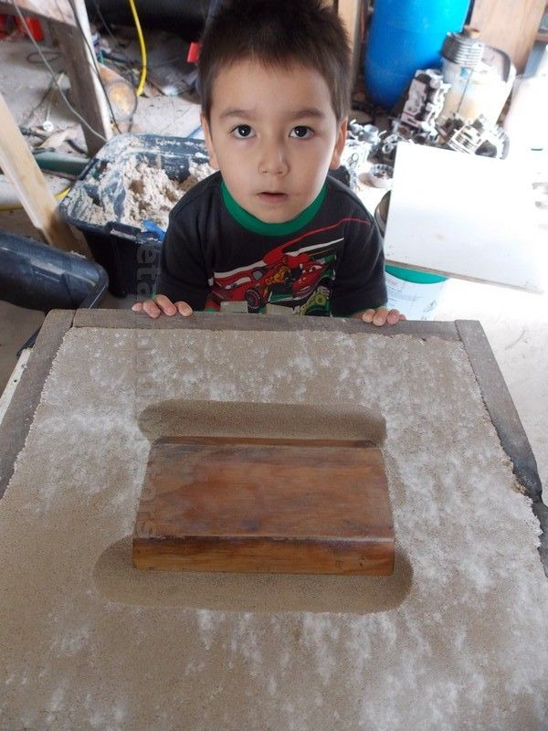
Pete, looking real good, who is the helper you have there in the photo. Good luck with the distributor cap and piston.

Happy New Year
 
Hi Danny
Thats my son Kevin, Hope he still looks up at me like that when he's 15 ;D
He just loves the sandbox, who knows maybe I can get him interested.
Happy new year
Pete
 
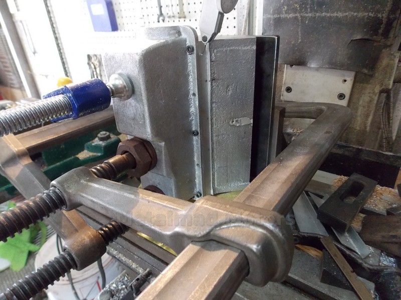
Hi Guys Spent a bit of time on the V8 today and bored out the big end on the Mill.
Forgot to take pictures but here is a pic of the set up and end bearings installed.
I need to get a Crank happening soon.
Pete
DSCN0429.jpg


DSCN0427.jpg
 
Hi Guys
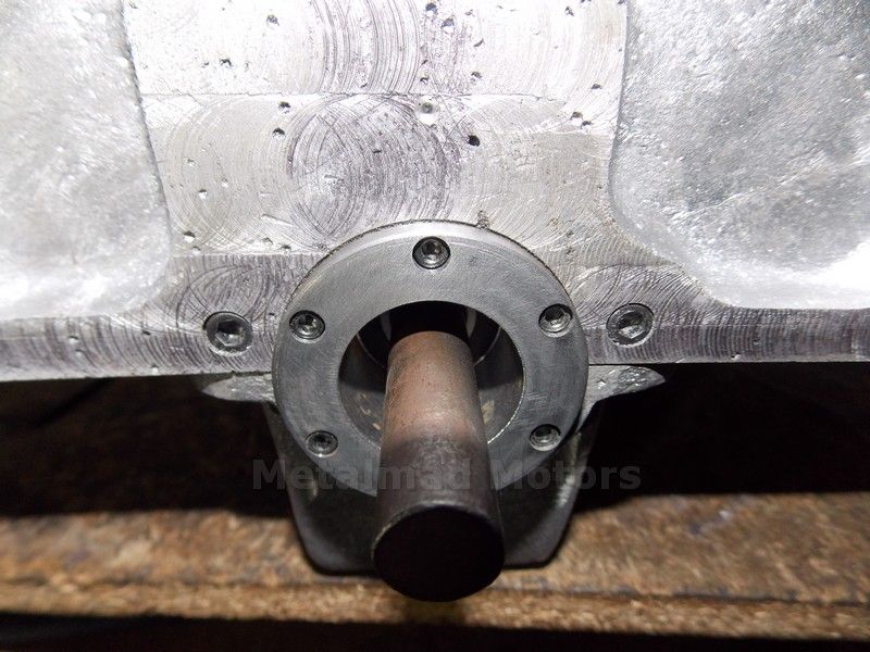
I made up the rear end plate today and bolted it on but have left it a little long so I can set up the endplay once the Crank is made.
The bit of half inch round is just for show :)
Pete
DSCN0431.jpg


DSCN0430.jpg


DSCN0433.jpg
 
Back
Top