A small steamboat powered by my Wiggins/Coles S.T. engine

Home Model Engine Machinist Forum

Help Support Home Model Engine Machinist Forum:

This site may earn a commission from merchant affiliate links, including eBay, Amazon, and others.

Kaleb

Senior Member
Joined
Jan 3, 2010
Messages
272
Reaction score
27
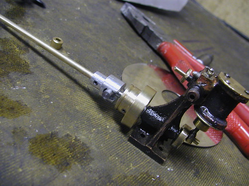
Now I've got my Wiggins/Coles S.T. running, I have decided to start work on a little steamboat powered by it.


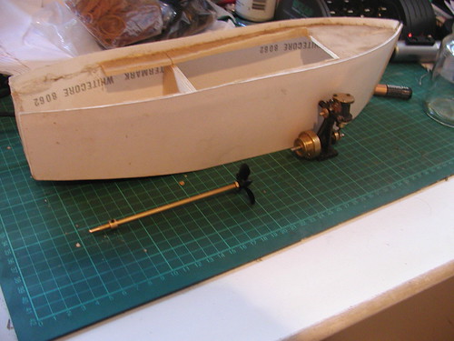
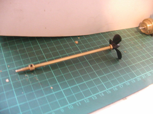
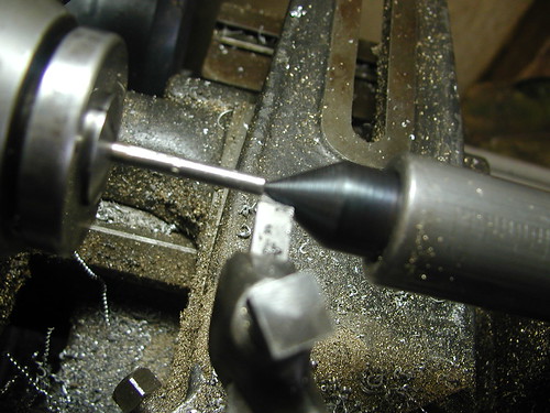
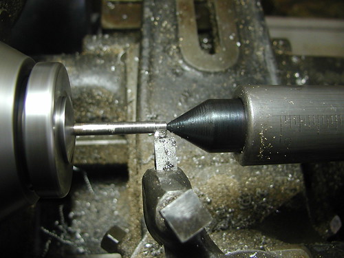
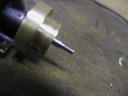
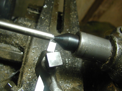
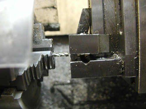
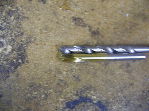
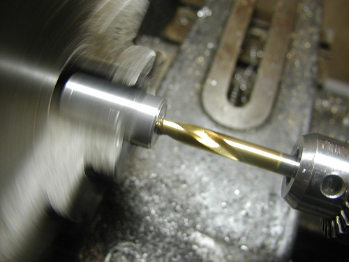
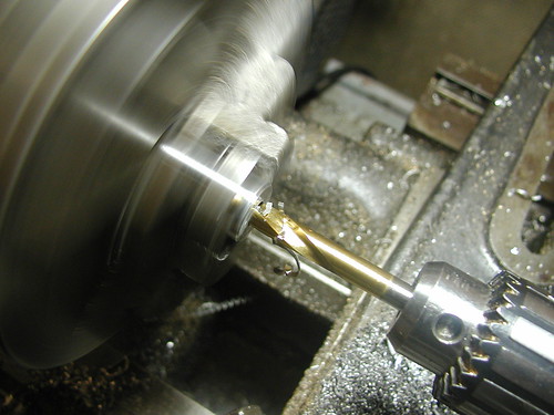
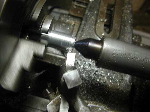
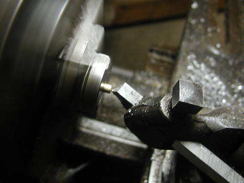
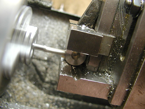
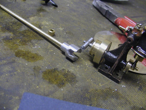
My next door neighbour gave me this part finished hull and prop shaft to use as the basis for the build. The hull will need some work to get it watertight, but the prop shaft is good to go. I'll also be building the boiler. I'm thinking of using a flexible coupling between the engine and prop shaft to give a bit more leeway when it comes to mounting the engine. I'm currently thinking of using either a universal joint or a beam coupling, but I'm not sure which would be best. I know of the method of using a piece of silicone tubing, but I think it would be better to use a proper coupling.
 
Will it be radio controlled? Looking forward to following this build. Especially the boiler
 
Looks like an interesting project. I'll be following with interest.

Chuck
 
I've made a start over the last week or so on a few smaller details.

The first thing I did was to caulk up all potential leaks in the hull. I did this with waterproof silicone caulk meant for use in aquariums, which I bought at Bunnings some time ago (Bunnings is a big hardware store chain in Australia and N.Z. for those who haven't heard of it.) I didn't get any photos of this, but the caulk has set, so the hull should be watertight. However, I will still need to dope the hull since it's made of balsa wood and cardboard.

I asked John Buckley for advice on what sort of coupling to use, and he told me a much simpler option, which I have termed a drive pin or Buckley coupling. It consists of a drive pin on the engine's crankshaft and a slotted bushing on the prop shaft.


First, I needed to thread the end of the crankshaft. I decided to machine it down to take an M3x0.5 thread, so I set it up in a 5/32" collet on the Hercus like so.


Turning down to take the thread.


Here's how it looks after threading, ready to take the drive pin.


Machining the drive pin.


Set up for milling a flat to go against the shoulder on the crankshaft, and to aid drilling.


Turning the female part of the coupling from some aluminium.


Now, a hole must be drilled right through the piece of stock, but first the hole must be started on centre. Above is a regular drill bit, which has a tendency to wander off centre unless there is something to guide it. Below is a spotting drill, which has a sharper taper on its end. This is used for making a divot to start the hole, and because of the sharper angle, a regular bit will always go to the centre of that, even if it's a different size.


Here's the spotting drill in use.


Drilling for the prop shaft.


The spotting drill is then used to increase the diameter of the hole at one end to allow plenty of clearence.


Turning down the end which will face the prop.


Drilling a hole for a grubscrew.


I decided to cut a small diameter section off the prop shaft and face it to get better clearence in the coupling.


Milling the slots for the drive pin.


The finished coupling. I'm very happy with the way it turned out. It runs very freely even when at an angle, and allows the engine to be quickly removed if needed.

Anyway, that's all for the moment.
 

Latest posts

Back
Top