No, you don't have to sign up to get the download. Select the "slow download" option---it isn't slow.---Brian
You are using an out of date browser. It may not display this or other websites correctly.
You should upgrade or use an alternative browser.
You should upgrade or use an alternative browser.
A new engine for fall---
- Thread starter Brian Rupnow
- Start date

Help Support Home Model Engine Machinist Forum:
This site may earn a commission from merchant affiliate
links, including eBay, Amazon, and others.
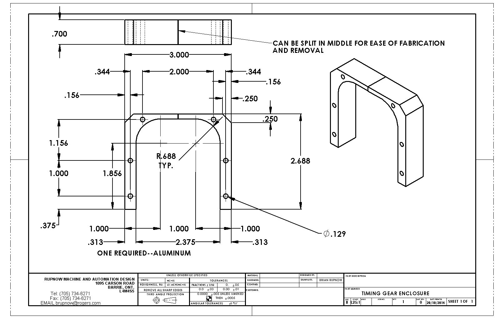
The engine runs well, but the gears are---ahh----noisy. I knew that they would be. They mesh well, and operate very smoothly now that I have an hours running on the engine. However, experience with other engines I have built sort of forewarned me that the open gearing would make a fairly noticeable "whirring" noise as the machine ran. That is why I made provision for an enclosure to go around the gears. An enclosure will cut down the noise quite a bit, will act as a containment for grease around the gears, and will provide some measure of safety (although I doubt I would have stuck my fingers in there anyways.)

- Joined
- Sep 2, 2011
- Messages
- 1,396
- Reaction score
- 387
Congratulations, its a beauty. nice sound and nice to watch.
Great Job / Work.
Bryan
Great Job / Work.
Bryan
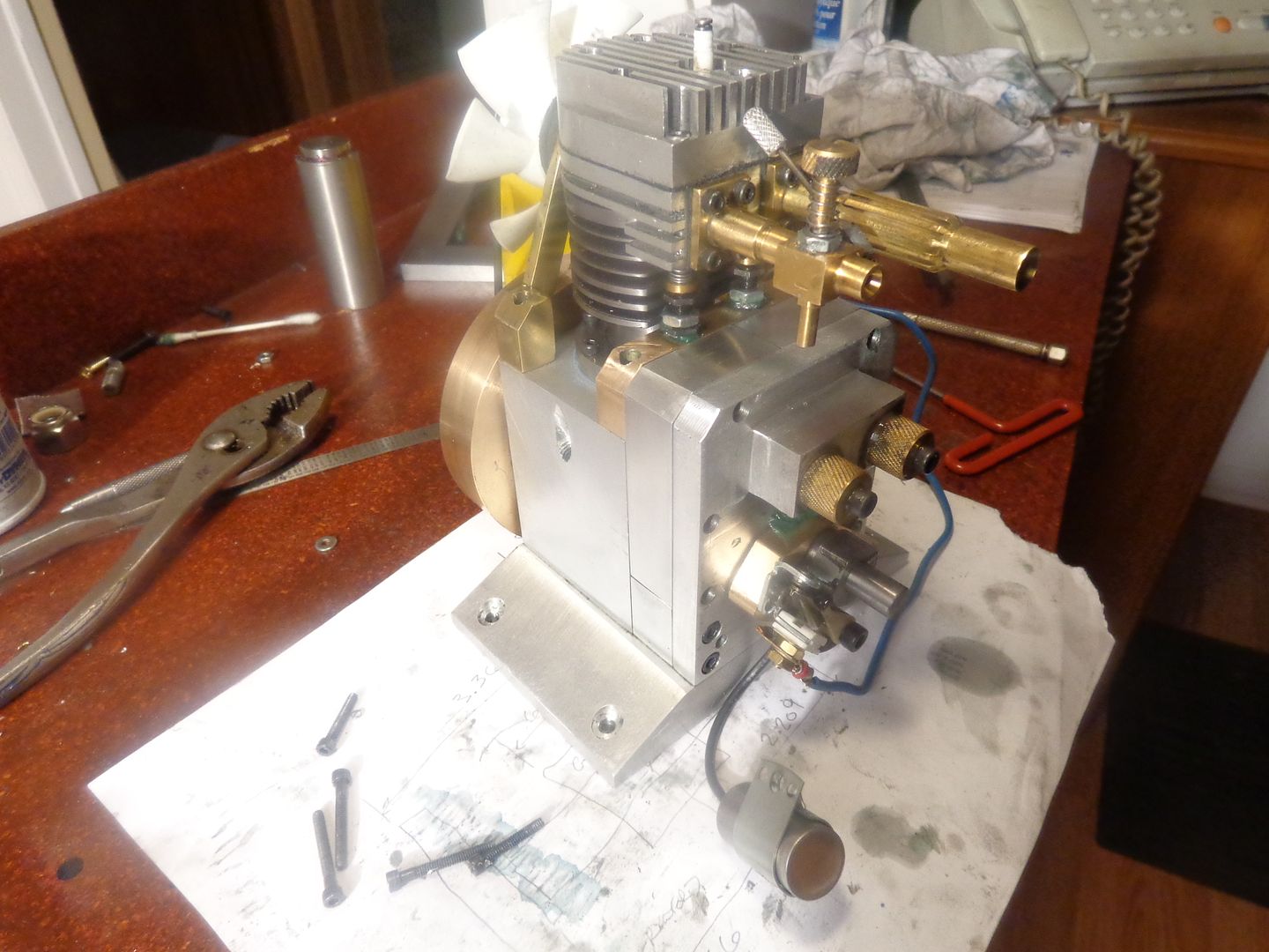
Thanks Bryan--Fabrication of the timing gear enclosure went very quickly with no problems. i did have to split it to get it on, as I had indicated on the drawing. The only problem I ran into is that I don't have any bolts long enough to bolt things together. I had to order a minimum quantity of one hundred #5-40 socket head cap screws x 1 1/4" long to get the 6 I need. That will probably last me for the rest of my natural life!!!

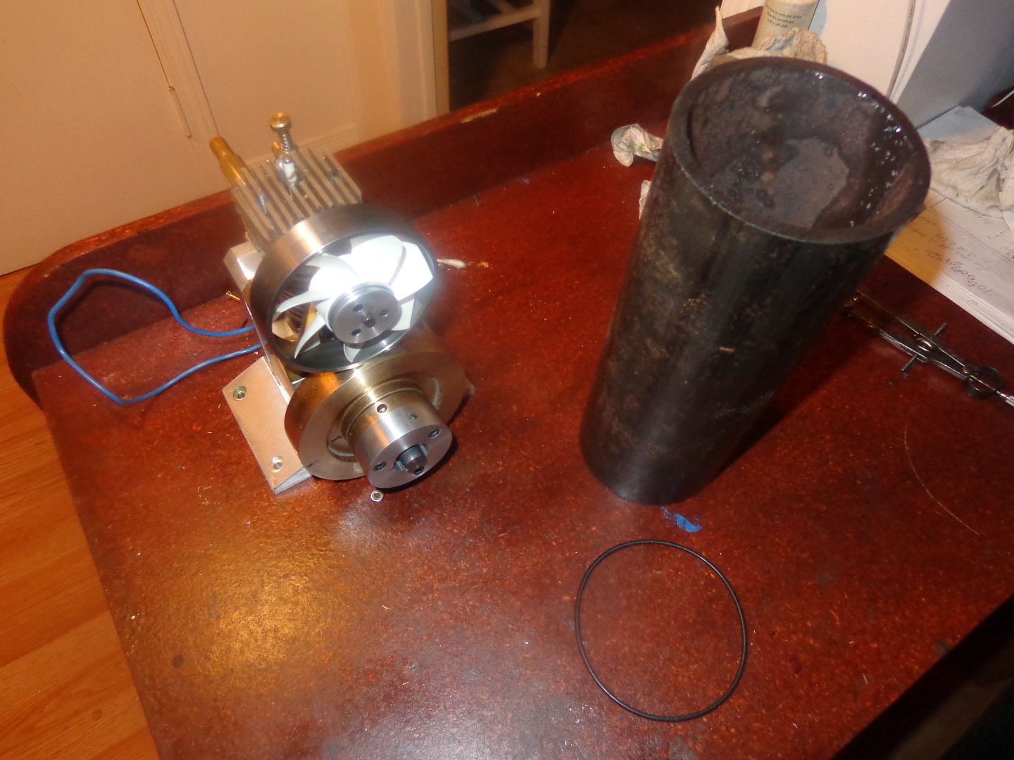
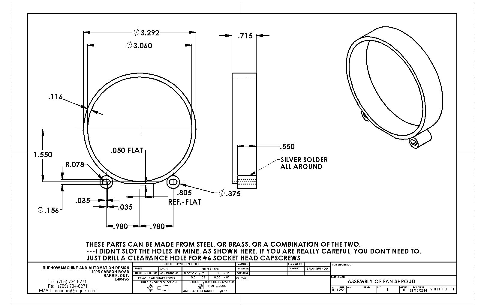
When Ringo sang the song "It don't come easy" I'm sure he must have been thinking about something like this fan shroud!!! The only tube/pipe I could find slightly larger than my 3" diameter fan was a piece of schedule #40 3" nominal diameter steel pipe. It has a 3 1/16" inside diameter. I don't like working with pipe in the lathe.--It's nasty stuff to hold if you don't have a bull nose live center for the tailstock (I don't) and it has a propensity for jumping out of a 3 jaw chuck and rocketing around the room. This forced me to take .002" deep very light cuts until I had things close to the outside diameter that I wanted to end up with. The wall is still a little thicker than I would have liked, but it was just getting too scary. I have had a slight change of plan----I was going to silver solder it to the fan support bracket but that would have given me no adjustability at all. I have come up with a rather novel solution for bolting it to the fan bracket instead, giving me a bit of wiggle room if it ends up interfering with the tips of the fan blade anywhere.

- Joined
- Oct 1, 2010
- Messages
- 1,408
- Reaction score
- 435
Brian,
I know, it's done. What is the O.D. of your fan? Could you use a piece of propane cylinder? (As in hand-held torch.)
--ShopShoe
I know, it's done. What is the O.D. of your fan? Could you use a piece of propane cylinder? (As in hand-held torch.)
--ShopShoe

$25.34
$34.99
Bowl Sander Tool Kit w/Dual Bearing Head & Hardwood Handle | 42PC Wood Sander Set | 2" Hook & Loop Sanding Disc Sandpaper Assortment | 1/4" Mandrel Bowl Sander for Woodturning | Wood Lathe Tools
Peachtree Woodworking Supply Inc
![DreamPlan Home Design and Landscaping Software Free for Windows [PC Download]](https://m.media-amazon.com/images/I/51kvZH2dVLL._SL500_.jpg)
$0.00
DreamPlan Home Design and Landscaping Software Free for Windows [PC Download]
Amazon.com Services LLC

$29.95
Competition Engine Building: Advanced Engine Design and Assembly Techniques (Pro Series)
Amazon.com Services LLC

$99.99
AHS Outdoor Wood Boiler Yearly Maintenance Kit with Water Treatment - ProTech 300 & Test Kit
Alternative Heating & Supplies

$519.19
$699.00
FoxAlien Masuter Pro CNC Router Machine, Upgraded 3-Axis Engraving All-Metal Milling Machine for Wood Acrylic MDF Nylon Carving Cutting
FoxAlien Official

$89.99
Outdoor Wood Boiler Water Treatment Rust Inhibitor- AmTech 300 & Test Kit
Alternative Heating & Supplies

$39.99
$49.99
Sunnytech Low Temperature Stirling Engine Motor Steam Heat Education Model Toy Kit For mechanical skills (LT001)
stirlingtechonline

$45.99
Sunnytech Mini Hot Air Stirling Engine Motor Model Educational Toy Kits Electricity HA001
stirlingtechonline

$94.99
$109.99
AHS Woodmaster 4400 Maintenance Kit for Outdoor Wood Boiler Treatment
Alternative Heating & Supplies

$180.50
$190.00
Genmitsu CNC 3018-PRO Router Kit GRBL Control 3 Axis Plastic Acrylic PCB PVC Wood Carving Milling Engraving Machine, XYZ Working Area 300x180x45mm
SainSmart Official

$39.58
$49.99
Becker CAD 12 3D - professional CAD software for 2D + 3D design and modelling - for 3 PCs - 100% compatible with AutoCAD
momox Shop

$17.90
$24.95
Backyard Building: Treehouses, Sheds, Arbors, Gates, and Other Garden Projects (Countryman Know How)
Amazon.com
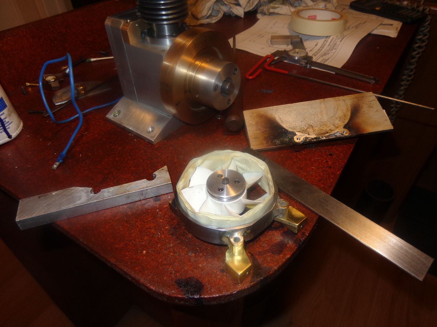
Going boldly where no man has gone be----Well, you get the idea.--Fan shroud is coming together nicely. At the last minute I decided to make the small pieces silver soldered to the steel hoop from brass. My reasoning--If I have to slot the holes with an end mill to move things around for fan clearance, the brass cuts easier. As you can see in the picture, the soldering job called for a couple of strange little "fixtures" to ensure that everything ended up where I wanted it to be. Now to ensure that the steel hoop will be concentric and clear the tips of the fan blades, I wrapped the fan with masking tape until I had .030" thickness of masking tape. Slid the hoop over that (snug fit) and will mark thru the brass ferrules welded to the hoop with a transfer punch to locate the holes I will tap in the fan stand.


Last edited:
Shopshoe--there are probably about a hundred different things that I COULD have done. The pipe solution came to mind because I knew that the i.d. of that size of pipe was 3 1/16" and wouldn't need any machining inside.
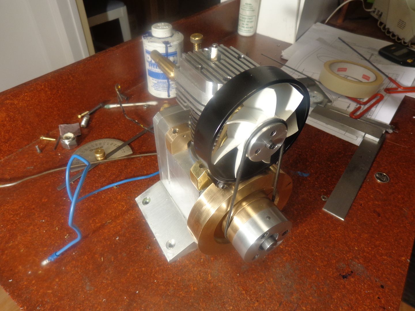
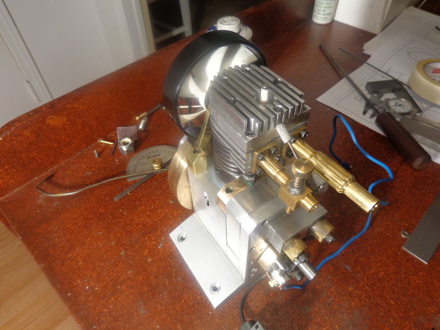
So, there we are!! Painted up pretty and done like dinner!! Nothing rubs nor scrubs, nor interferes, but a business card won't fit into the gap between the flywheel and the bottom of the fan shroud.--But it does clear. And that, my friends, was the very last part I had to build for this engine. I have to wait a couple of days for my long bolts to come in that hold the timing gear covers in place, but that's it. I will post one more video before I'm done, showing the engine running at its slowest and fastest speeds because someone has requested it, but other than that, I'm finished. This has been a long thread, as I knew it would become when I started it in July, but it's been fun and interesting. I encourage anyone out there who has at least a couple of i.c. engines "under their belt" to build this engine. ---Brian


Swifty
Well-Known Member
Thanks very much for all the posts Brian, it's a great looking engine.
Paul.
Paul.
Thanks so much for your hard work and the drawings for your latest engine !
Brian
Brian
- Joined
- Dec 31, 2010
- Messages
- 820
- Reaction score
- 220
A wonderful looking and running engine. I like the looks better when the gears are enclosed even though it hides the interesting bits. Makes the engine look like it's ready to install in something.
Fantastic work.
Thanks Brian
Sage
Fantastic work.
Thanks Brian
Sage
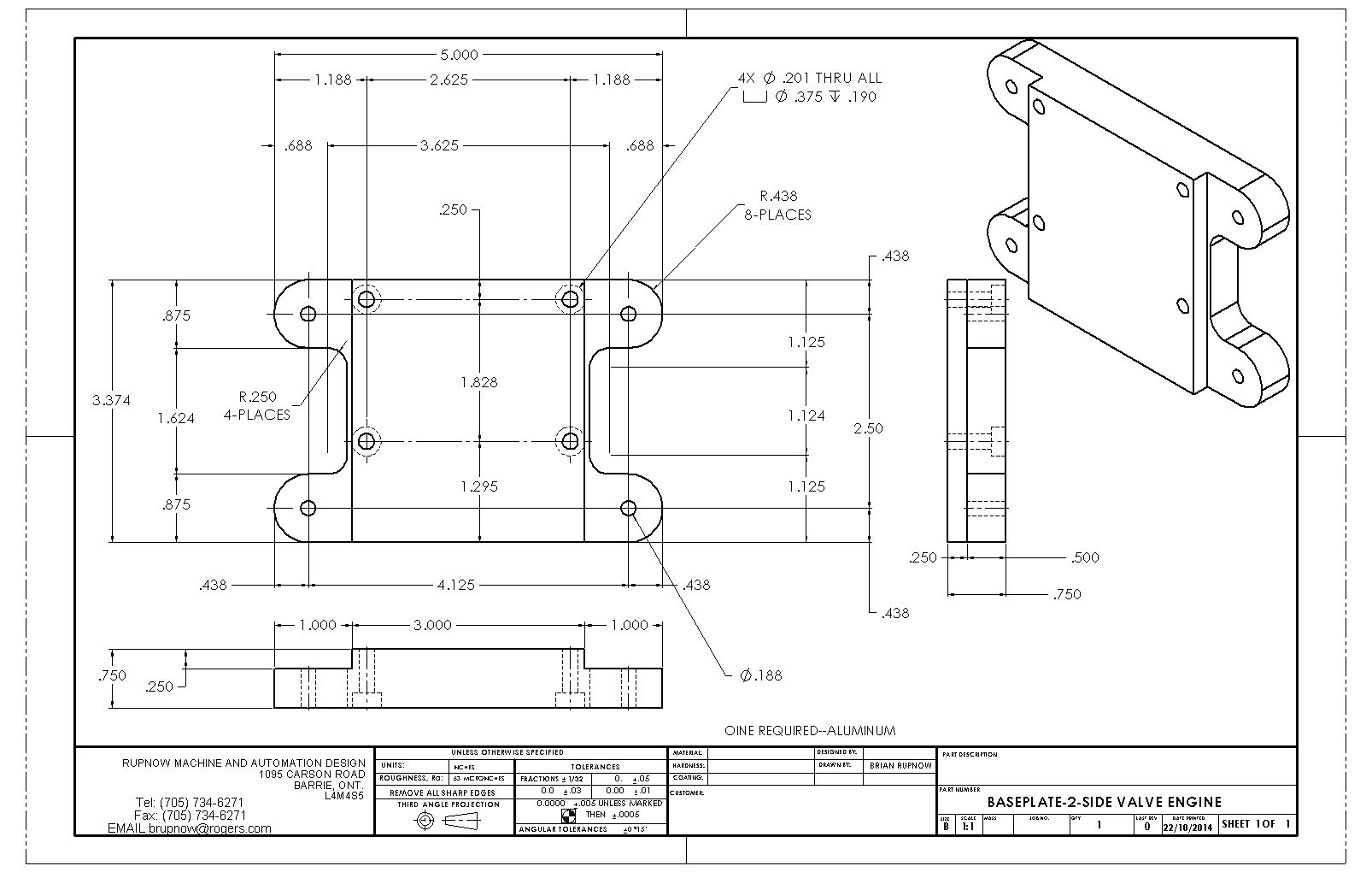
Liar Liar--Pants on fire---I said I wasn't going to post anymore but---I have never really liked the base I made for this engine. Oh, it was a lot better than the long angles that I had first proposed, but somehow it never looked--uhh---industrial enough for me. so--Today being free time, and having a bit of 3/4" aluminum left over, I made a new base. I like it much better.
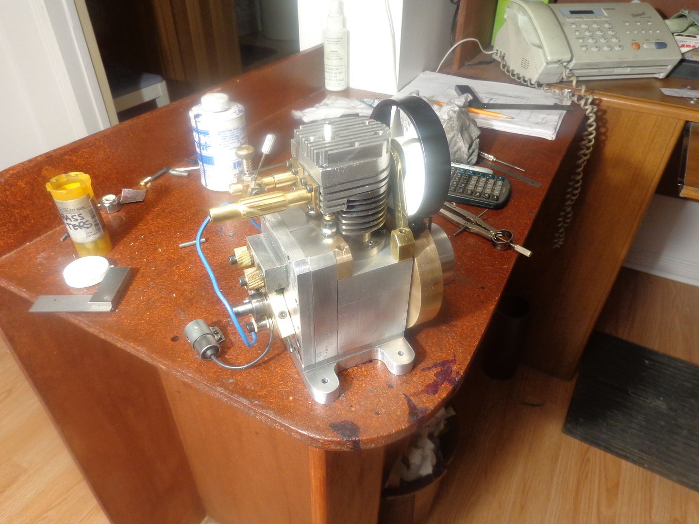


As Bugs Bunny would have said----That's all folks. Thanks for following.---Brian
[ame]https://www.youtube.com/watch?v=6mQeqhapvJo&feature=youtu.be[/ame]
[ame]https://www.youtube.com/watch?v=6mQeqhapvJo&feature=youtu.be[/ame]
- Joined
- Oct 1, 2010
- Messages
- 1,408
- Reaction score
- 435
Brian,
That's great and sounds great. It looks like the Chuck Fellows Carb. is working very well with excellent control. I like steady running at about the speed you're running: Don't like high-revvers so much.
Thanks for sharing your work all the way through. I have followed it every day.
--ShopShoe
That's great and sounds great. It looks like the Chuck Fellows Carb. is working very well with excellent control. I like steady running at about the speed you're running: Don't like high-revvers so much.
Thanks for sharing your work all the way through. I have followed it every day.
--ShopShoe
Shopshoe--Thank you for being a loyal follower. Pat--I haven't heard from you in ages. Did you ever finish your build of the original Rupnow engine?---Brian
Brian ...
Unfortunately, I'm stalled and haven't done anything on it since my last update.
It's just that I'm so busy with customers that by the time I get a break I'm beat and or have family obligations. I even hired a part time helper to do some of the work. Every time I think I going to be able to slow down someone needs something yesterday.
Although this is a good thing it is taking a toll on this old body.

But the Rupnow engine is on the shelf in sight as a reminder that as soon as I can I will get back to it and get her done.
Later,
Pat H
Unfortunately, I'm stalled and haven't done anything on it since my last update.
It's just that I'm so busy with customers that by the time I get a break I'm beat and or have family obligations. I even hired a part time helper to do some of the work. Every time I think I going to be able to slow down someone needs something yesterday.
Although this is a good thing it is taking a toll on this old body.
But the Rupnow engine is on the shelf in sight as a reminder that as soon as I can I will get back to it and get her done.
Later,
Pat H
Judging by the number of downloads I have had for the plans of this engine, someone, somewhere , is going to build it. I am going ahead with a gas tank bracket and gas tank for it, so will post them as "supplementary drawings" to the main download package. The bracket is located right in the center of the engine block, and the underside of the bracket is 1" below the top of the block. This will place the top of the tank about 1/8" below the center of the carburetor.
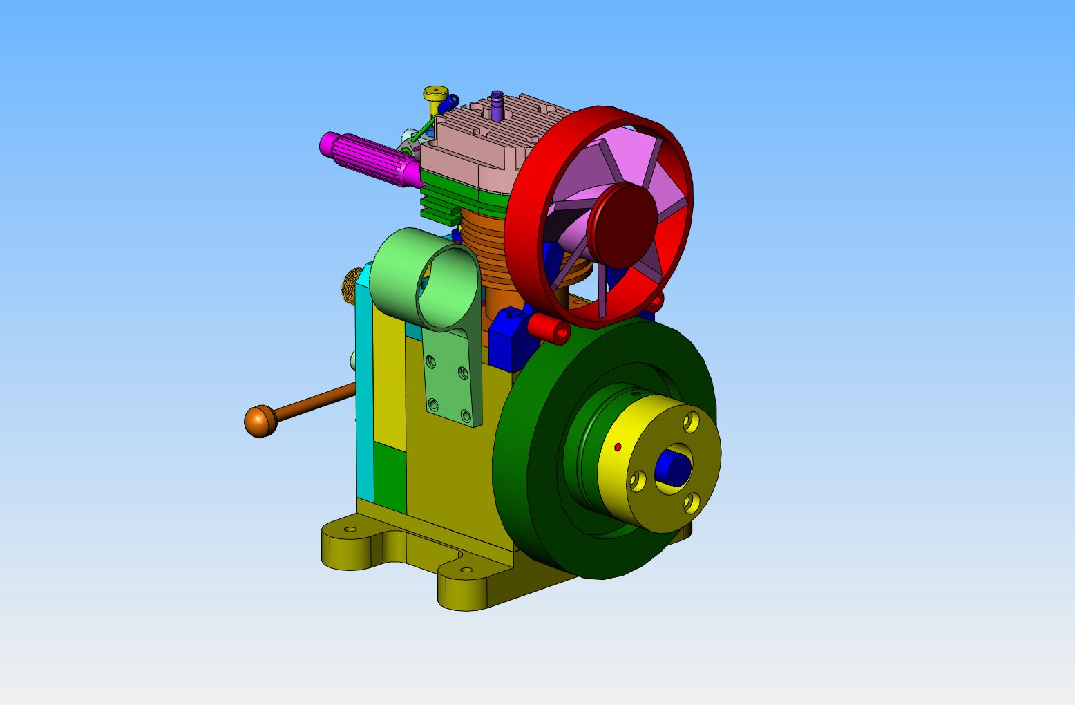
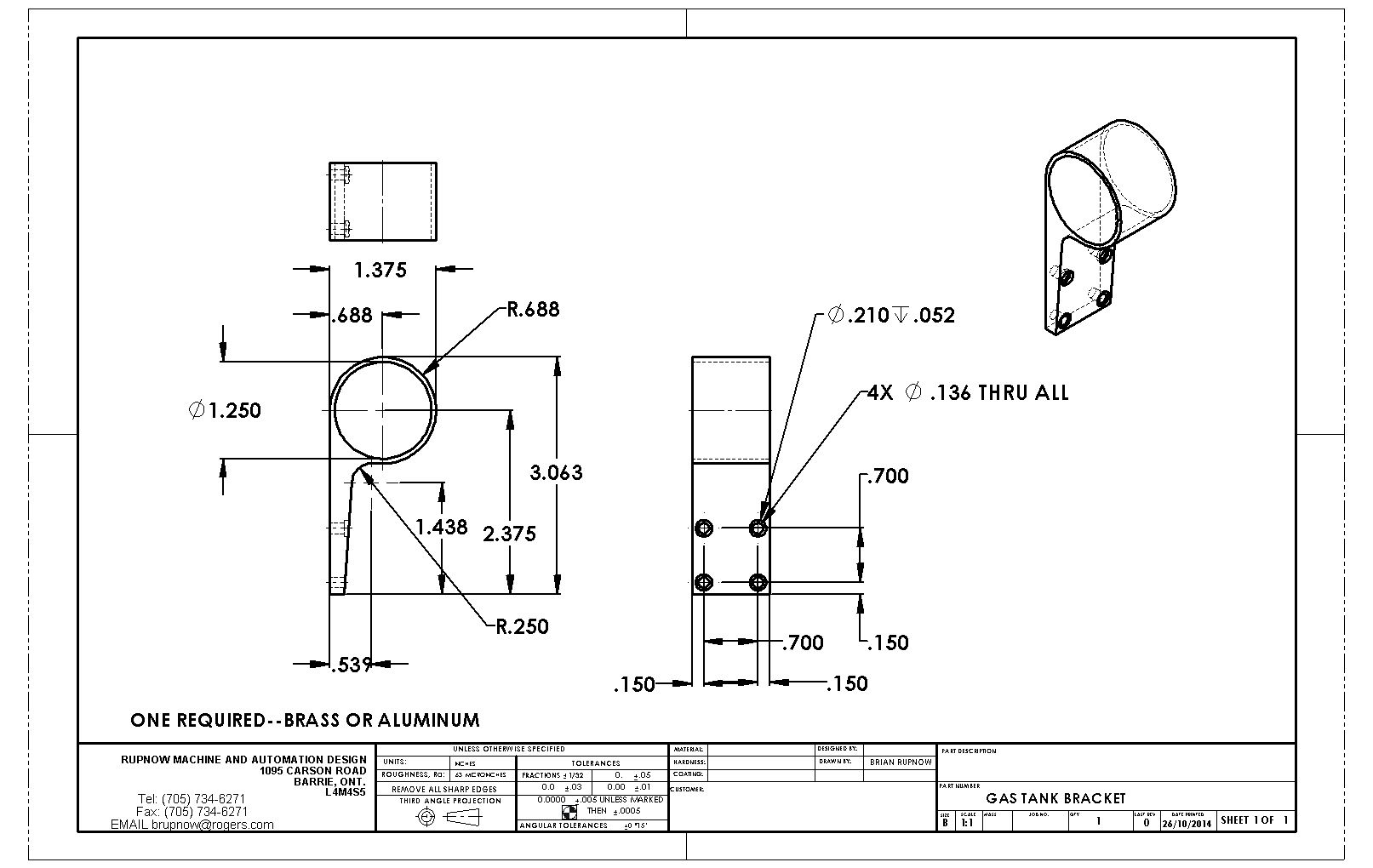


I spent all of yesterday fighting "gas tank wars". What should have been a very simple and straightforeward silver soldering job left me frustrated. All of the joints looked good, but when I put a rubber tube on the outlet spigot, then put the tank underwater and blew into the tube, I got a stream of bubbles coming out of the one end. I resoldered it twice, with the same result each time. Finally I set the whole tank up in the lathe and drilled/bored the leaking end completely away, made a new brass end insert and silver soldered it again before I went to bed. As of right now it doesn't leak, as per the "blow test" but I haven't filed away the excess silver solder either. I am waiting for my wife to get up before I start any power equipment in my shop, but I sincerely hope that when I get my last solder joint "cosmeticized" that I don't see any more bubbles!!
Similar threads
- Replies
- 95
- Views
- 12K
- Replies
- 22
- Views
- 2K


