A new attempt at making piston rings

Home Model Engine Machinist Forum

Help Support Home Model Engine Machinist Forum:

This site may earn a commission from merchant affiliate links, including eBay, Amazon, and others.

Brian Rupnow

Design Engineer
Project of the Month Winner
Joined
May 23, 2008
Messages
15,251
Reaction score
8,533
Location
Barrie, Ontario, Canada
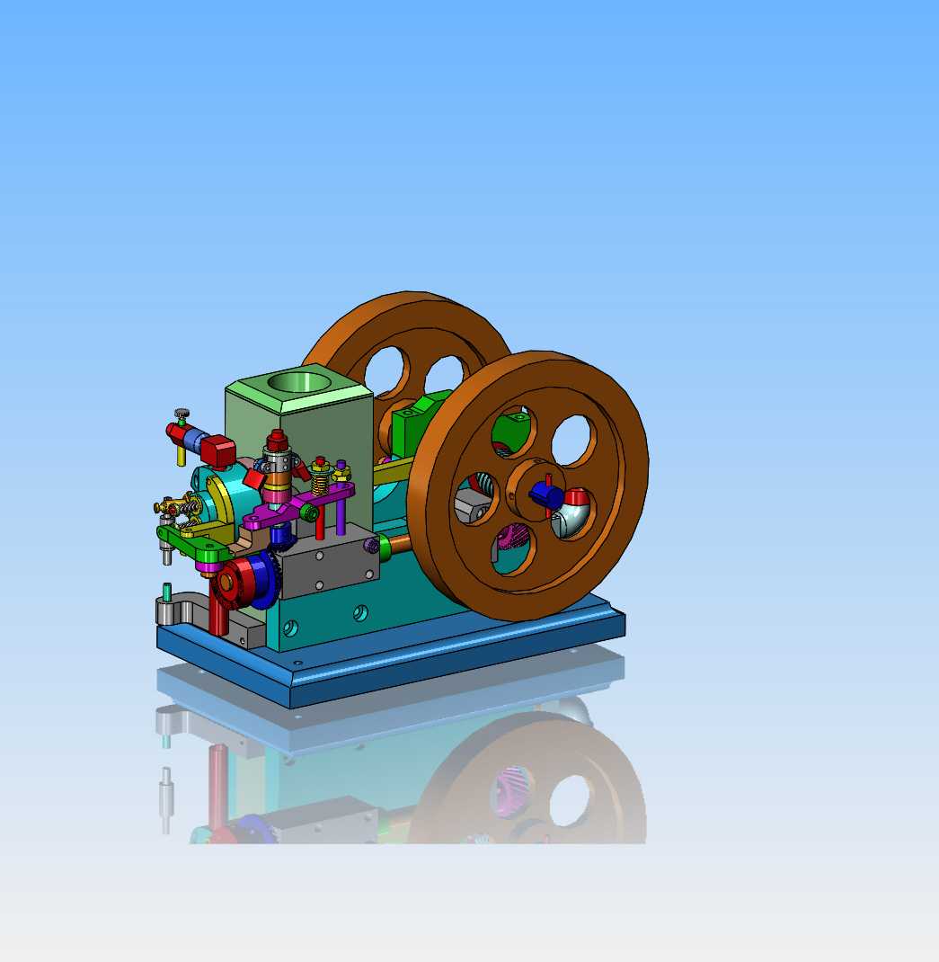
Let me start out by saying that I have made my own piston rings in the past---and failed dismally. I was so disheartened by my failed attempt that I went to Viton o-rings and never looked back. Now I have ten or twelve years engine building experience, and I am going to try again. I have a 1" bore side shaft engine which I built a few years ago with a Viton ring, and it runs very good, and has incredible compression. I have chosen this engine because I can undo the con-rod bolts and remove the piston without disturbing any of the other engine settings. This will require that I machine a new piston and two rings.
SY2gPr.jpg
 
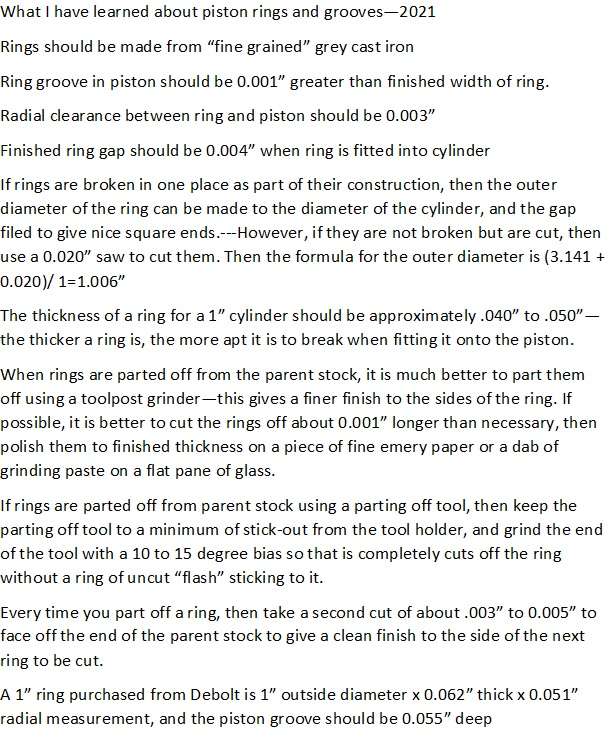
After considerable reading of books by Malcolm Stride, Philip Duclos, L.C. Mason and various posts by George Britnell, I have compiled this list of things related to ring making. This information is not "absolute", as some of the information given by one author tends to disagree with information given by a different author.
vdjzBR.jpg
 
Last edited:
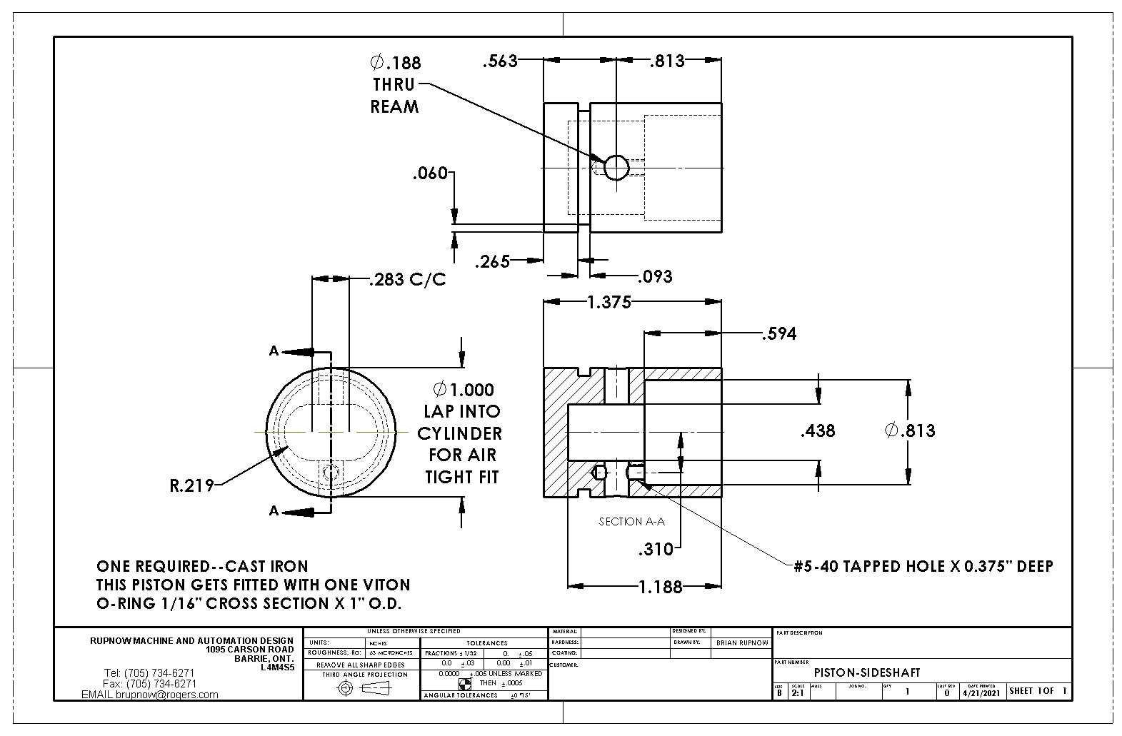
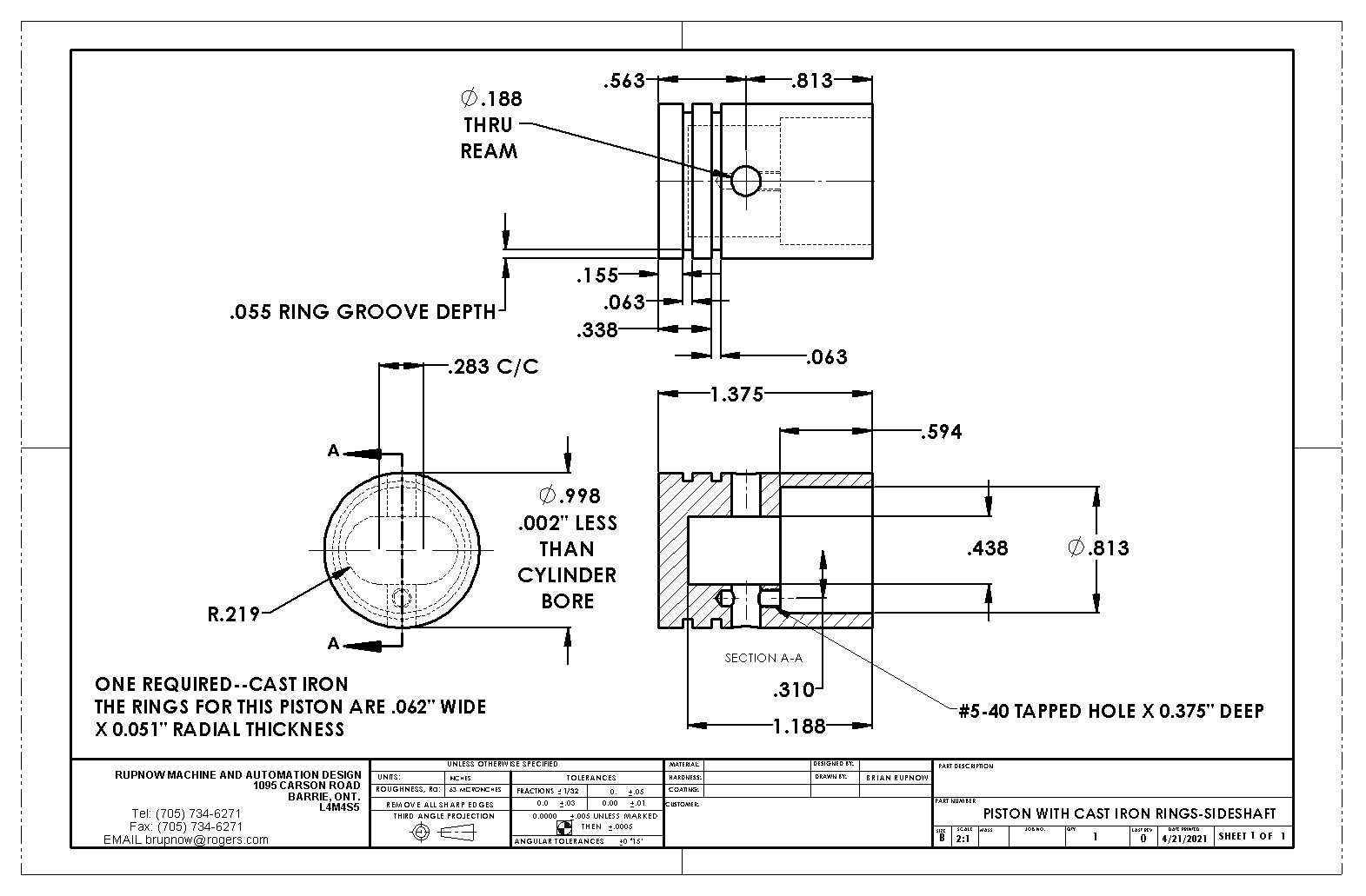
The drawings below show the piston "as built" for one 1/16" cross section Viton o-ring, and the same piston redrawn for a piston that accepts two cast iron o-rings to match the rings supplied by Debolt. (I will be making these rings to the same dimensions as two rings purchased from Debolt for my Vertical i.c. engine-2021). Note that nothing on the piston changes except the information relating to ring width, depth, and location.
0GDWMc.jpg

1o5kQA.jpg
 
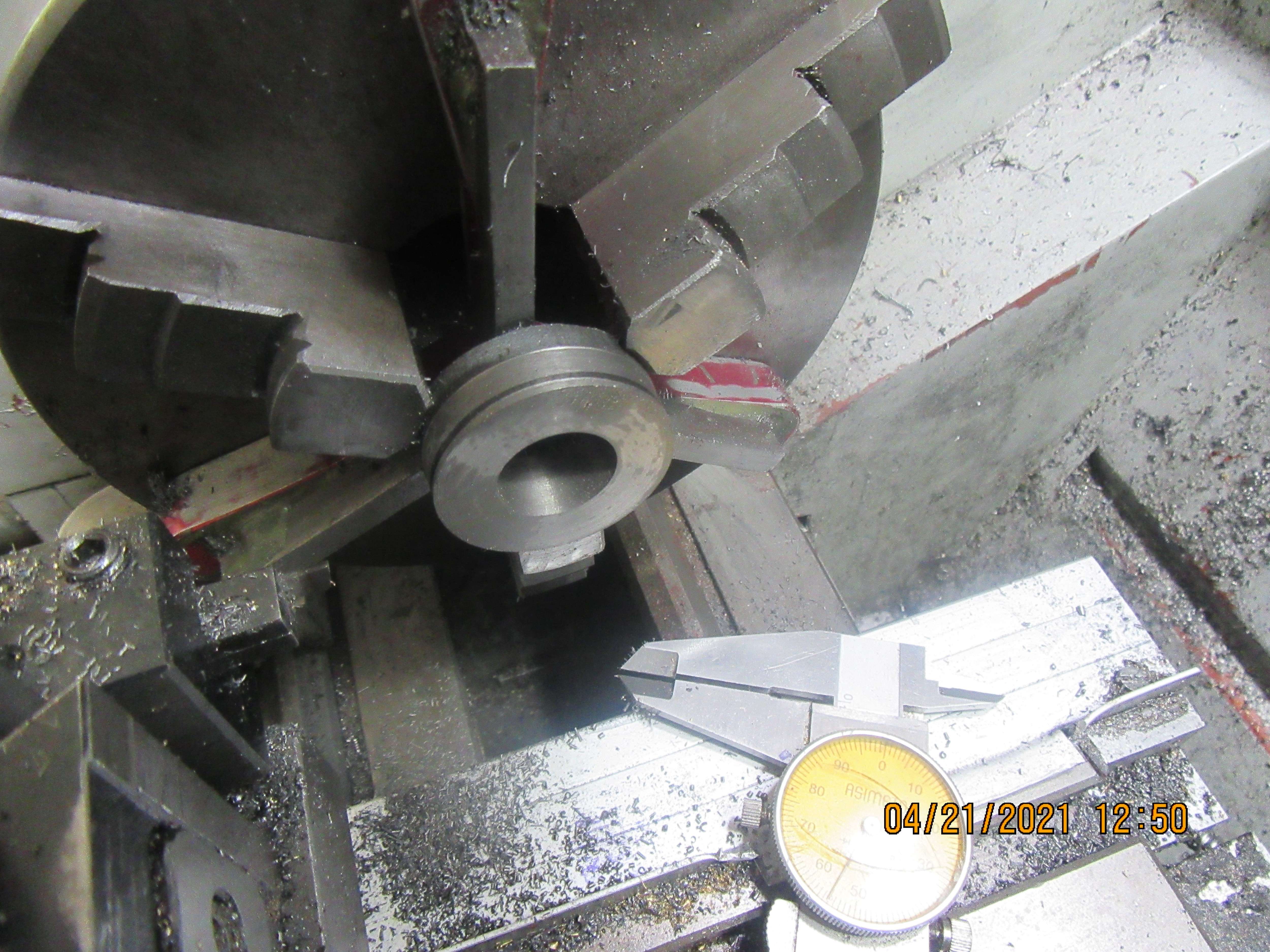
The first thing I wanted to check was---Does my .062 wide cutting tool cut an .062" groove in cast iron on a straight in plunge cut. Apparently not. The cutting tool does actually mike at .062 wide", but the slot it cuts in cast iron on a straight in plunge measures 0.057" wide. The top of my cutting tool has a strange shape to it (as bought) so next thing I'll try is grinding it flat and then do this test again.
XzocbJ.jpg
 
Okay--After a regrind of the top surface of my parting off tool so that it is absolutely flat and a second groove cut in cast iron, the groove is still measuring .057" wide. That's okay. As long as I know, then I can live with that. I could regrind an hss toolbit to give me an exact .062" groove, but I don't really want to have to do that.
 
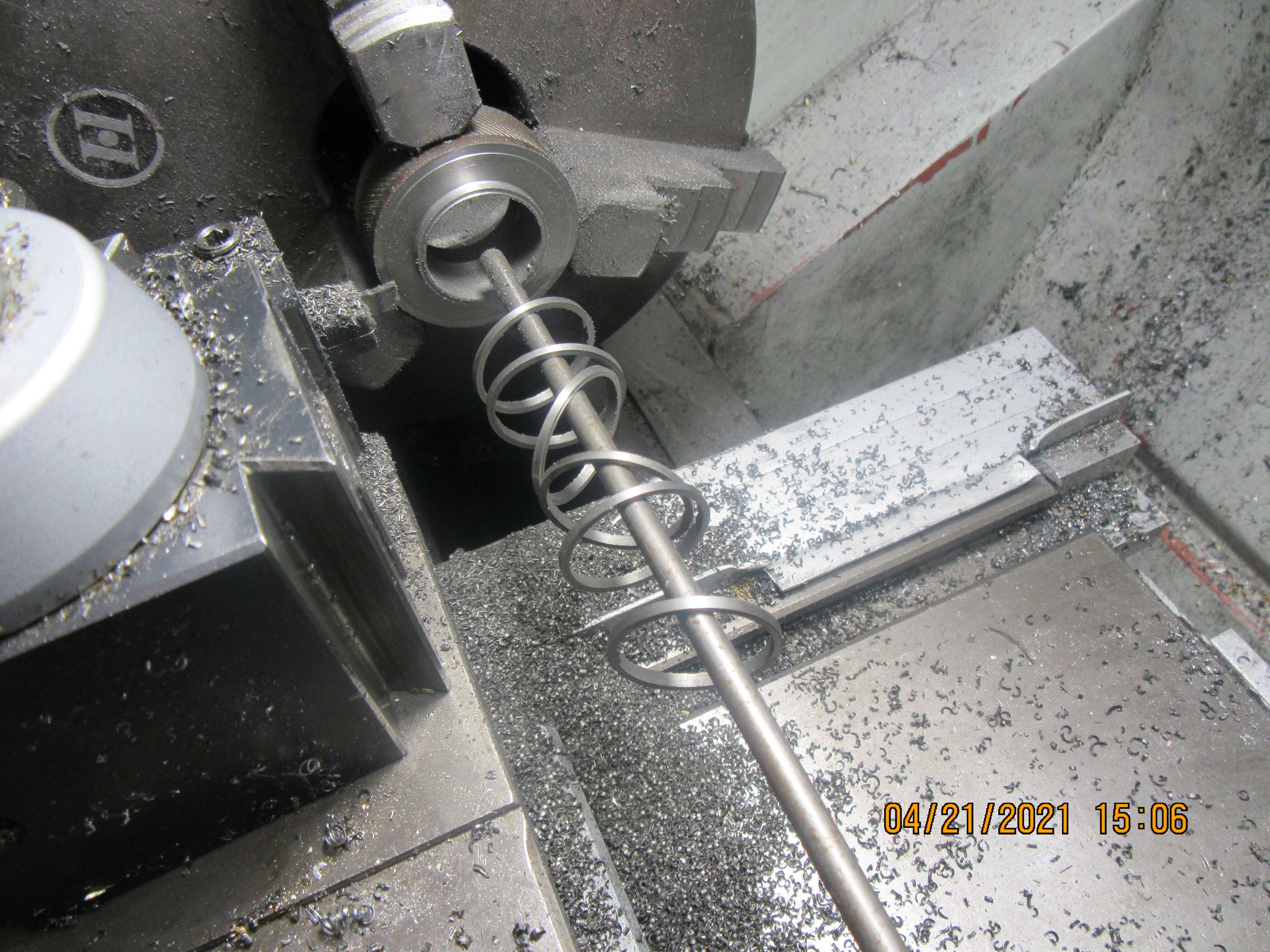
I was able to part off 6 rings with no problem. The math is a little weird, and I don't really know why. The ring closest to the right side of the page is 0.070" wide, but was supposed to be .062" wide. I set my parting tool against the end of the piece in the lathe, then using my DRO I moved it 0.125" towards the headstock. In theory that should have taken a cut .0625" wide and left a ring .0625" wide. After cutting and measuring the first ring, I moved the cutting tool 0.005" towards the headstock and took another cut to clean up the end of the stock. All subsequent moves were limited to 0.115" and that yielded rings approx. 0.065" wide. That should be about right because the rings still have to be cleaned up on both sides with some fine emery paper.
pxRFJz.jpg
 
If that first ring had been 0.068 it would make sense -- 0.125 - 0.057 = 0.068. Maybe it's 0.068 with .002" worth of roughness or tilt screwing up the measurement?
 
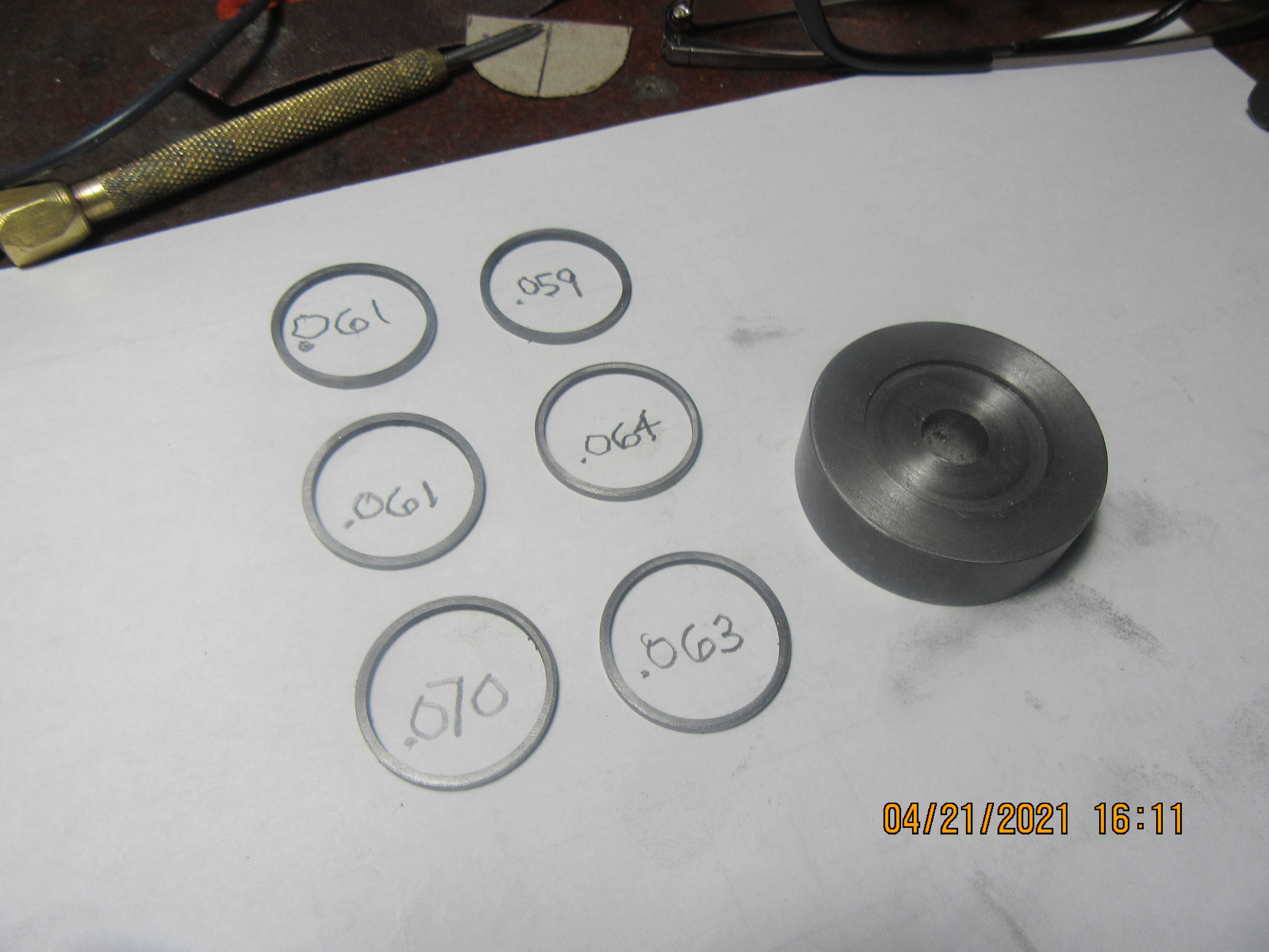
Here we have the six rings, polished on both sides with 150 grit, then 600 grit emery paper on a flat cast iron surface with some wd40. The thickness of each ring is printed inside the ring. I will lap that 0.064" ring a bit more and bring it down to 0.061" thickness.
I don't know if I can bring the 0.070" ring down in thickness by lapping, but I will find out. The recessed fixture that I held the rings with while lapping them is in the picture, with an 0.040" recess in the face, but it doesn't show up very well. One of the websites I looked at before undertaking the making of these rings suggested deburring the inside corners/edges with a circular porcelain stone. I don't have such a thing, but will call around to my tooling suppliers in Barrie and see if I can buy one.
kmveQS.jpg
 
The two rings that were "overthick" both came down to 0.061" with a bit more lapping. I've read so much about making rings in so many different places, I can't remember where I read about the porcelain sharpening stone that was used to deburr the inside edges of the rings. Maybe I had it wrong. Maybe it was "ceramic" sharpening stone. It looked to be about 3/8" diameter x 4" or 6" long, and would have to be a reasonably fine grit. If anybody knows where I can buy such a thing in Ontario, Canada, please let me know.---Brian
 
I have made dozens of rings from 3/4" - 1-1/4" adhering closely to the Trimble method published in Strictly IC. They work great and I don't think I have ever broken one. I parted them using a ThinBit carbide grooving tool. No toolpost grinder here.
 
I'm late to the party Brian, but Mr Crispin on YouTube did a couple of videos on making piston rings. He also covers breaking and heat treating the rings.

Might be worth a look:

Part 1:
Part 2:
 
Due to Covid shutdowns and my own impatience, I will wrap a piece of 220 grit emery cloth around a wooden dowel and use that to deburr the inside/edges of my rings. Someday, when this damned plague is over, my wife and I will drive down to Vaughn and pick up one of these tools from Lee Valley Tools.
 
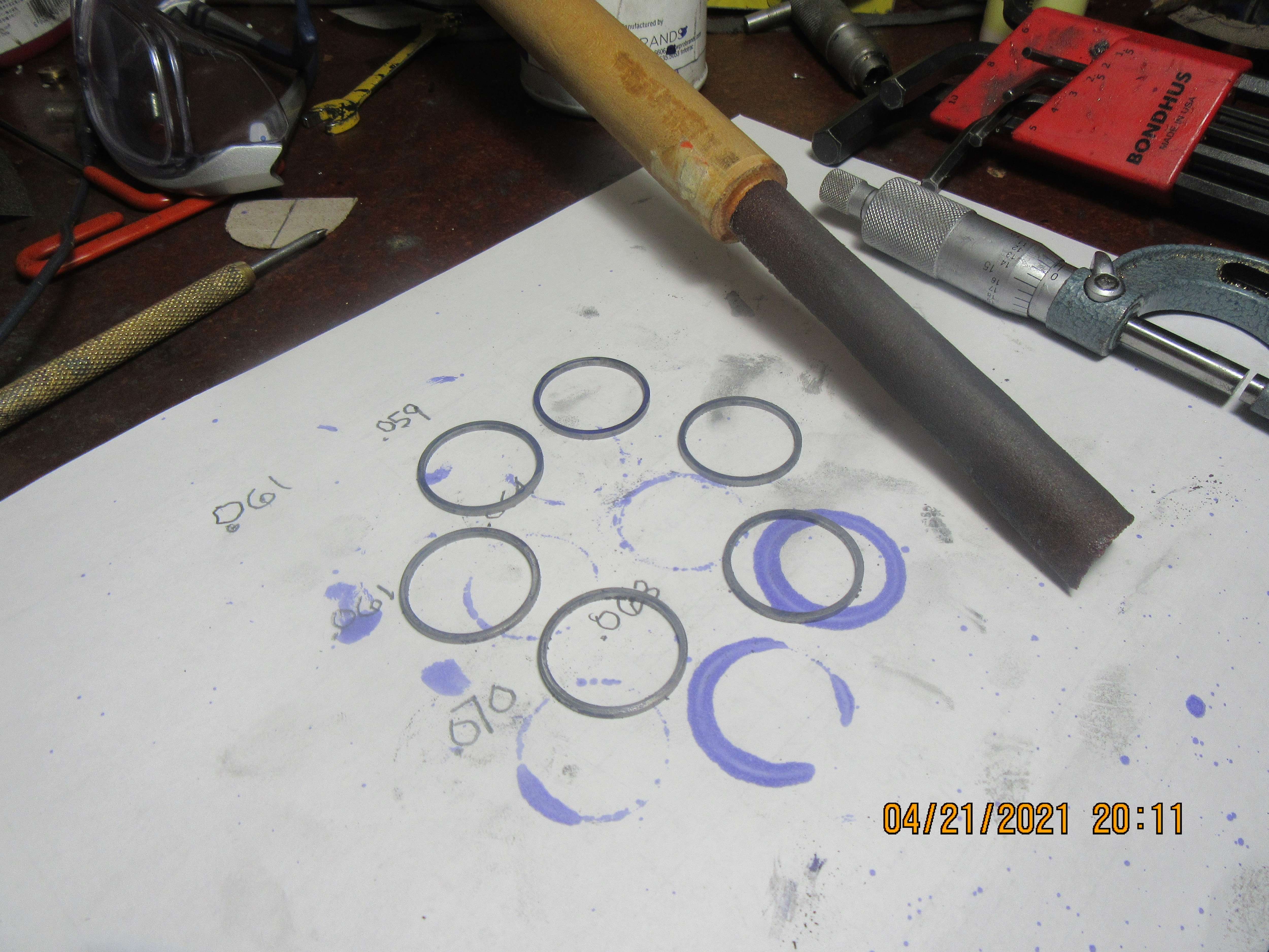
And here we have a quick and nasty round ceramic file (220 grit emery paper glued around a turned broom handle), and my rings are all deburred on the inside/edges. Tomorrow I will break them in a vice, file the ends, try them for size in a cylinder, and then heat treat them.
0VjSZz.jpg
 
And here we have a quick and nasty round ceramic file (220 grit emery paper glued around a turned broom handle), and my rings are all deburred on the inside/edges. Tomorrow I will break them in a vice, file the ends, try them for size in a cylinder, and then heat treat them.
0VjSZz.jpg
Liking your mini series on rings I to have struggled in the past. Will be interested in the final results, keep up the good work.
 
Hi Brian, from my limited (industrial) knowledge, care keeping the top and bottom faces parallel is paramount. Industry uses a surface grinder and is incredibly precise on ring thickness and parallel faces. Not tooling in the hobby workshop. The fine linishing you are doing is excellent - the finer finish the better! I suggest the groove in your tool should be the target depth of the thickness of your rings? Do you work the whole in circular or figure of 8 patterns on the linishing paper? Avoid straight back and fro motion when doing this. I would suggest a rotation of the ring holder of between 50 and 70 degrees after maybe every 5 figure of eights? I am sure you are well experienced doing this, but I have learned by getting it wrong!
Well done for another excellent tutorial.
K2
 
Just a couple of questions / observations.
How did you measure the width of the ring groove to cut in the piston? I'm perplexed by how it came out narrower than the width of the parting tool. Try some feeler gauges in the slot for an accurate measurement.

If you are lapping the rings to thickness then be careful that the two sides are parallel by measuring them in various places around the ring. I've found that even using the tool you mentioned to hold them, hand pressure can result in unevenness. Rotating the ring periodically can help.

Finally DO NOT follow the instructions by Mr. Crispin. He made all the classic mistakes and many people pointed them out in the comments in his first video. So much so that he made a second video where he made new rings, correcting some of the issues but still made mistakes. In the end he admitted they where "Good enough" and moved on. They might be good enough for his steam engine.
 
Last edited:
BTW. One more thing. Your solution to use the stick and emery cloth was sufficient to knock off the burr on the inner edges. No need to purchase a special ceramic stone. You're not trying to round the edges. Just a light touch to be sure they are not razor sharp.

Good stuff. Looking forward to your results.
 
The drawings below show the piston "as built" for one 1/16" cross section Viton o-ring, and the same piston redrawn for a piston that accepts two cast iron o-rings to match the rings supplied by Debolt. (I will be making these rings to the same dimensions as two rings purchased from Debolt for my Vertical i.c. engine-2021). Note that nothing on the piston changes except the information relating to ring width, depth, and location.
0GDWMc.jpg

1o5kQA.jpg
Hi Brian
I have been through the same ups an downs with the cast or "O" ring piston seals. I had much trouble getting the O rings in the bore using the dimensions form charts seems had to keep changing the width but once the O ring just touches is all you need. Suspect the charts dimensions are in general for a different applications. The compression seems a bet more with the O rings at lest in one of my engines. Big + is no risk in put them on the piston an once some lube they are good to go for extended run times with just some lube for the piston. Would be interested to hear if you were successful using the charts grove values.
Harvey
 

Latest posts

Back
Top