- Joined
- Jul 16, 2007
- Messages
- 3,025
- Reaction score
- 1,109
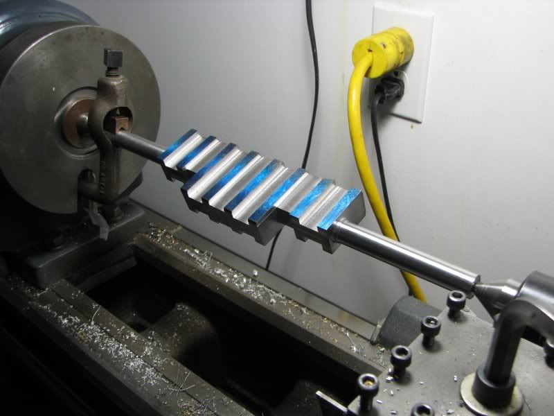
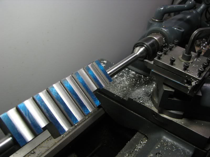
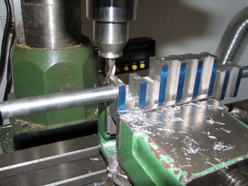
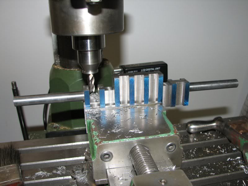
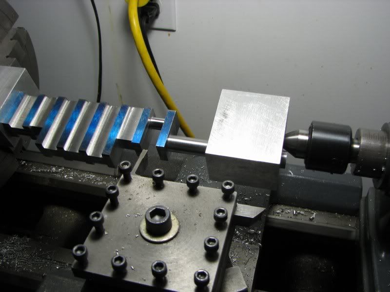
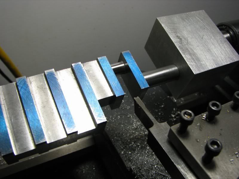
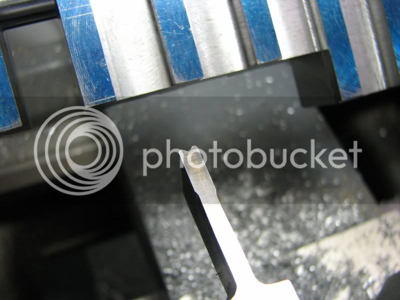
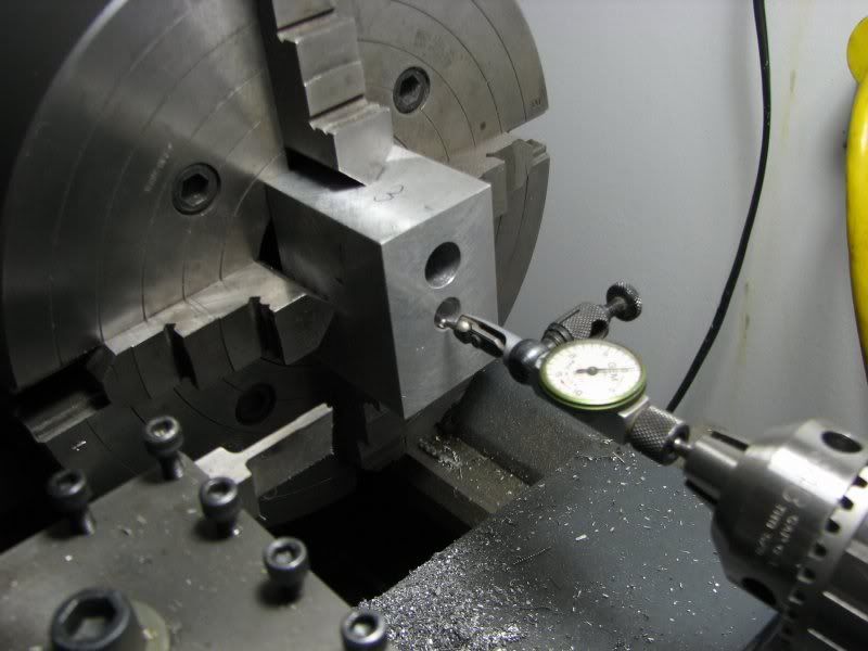
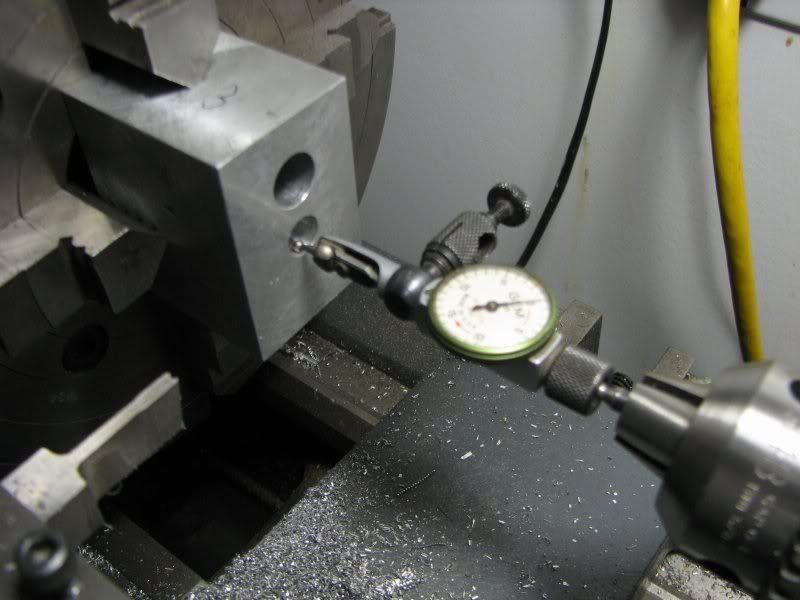
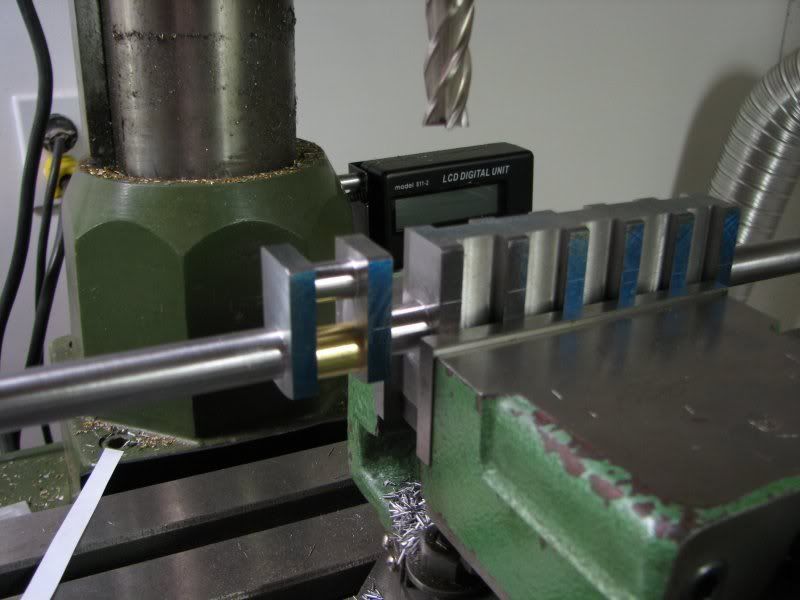
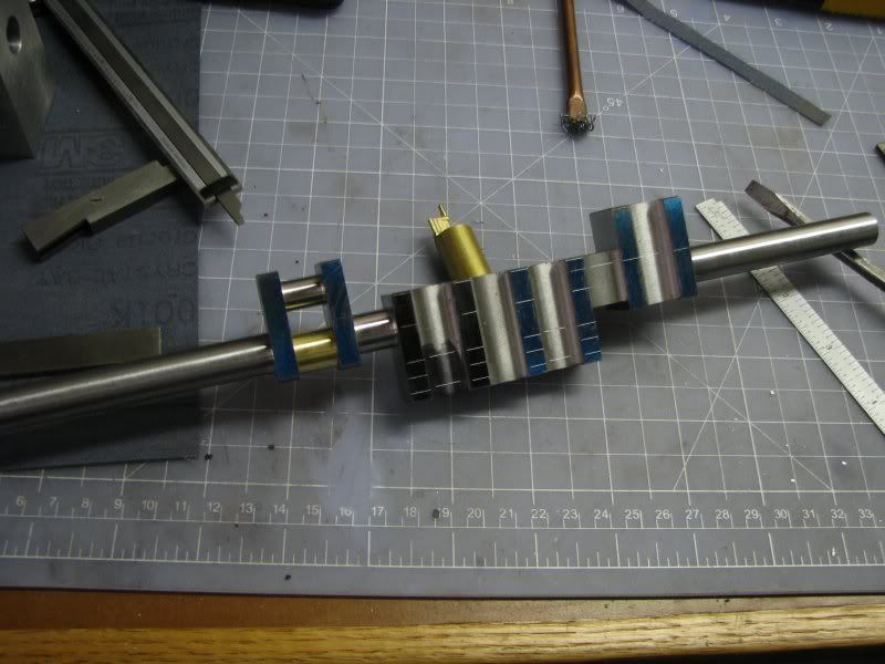
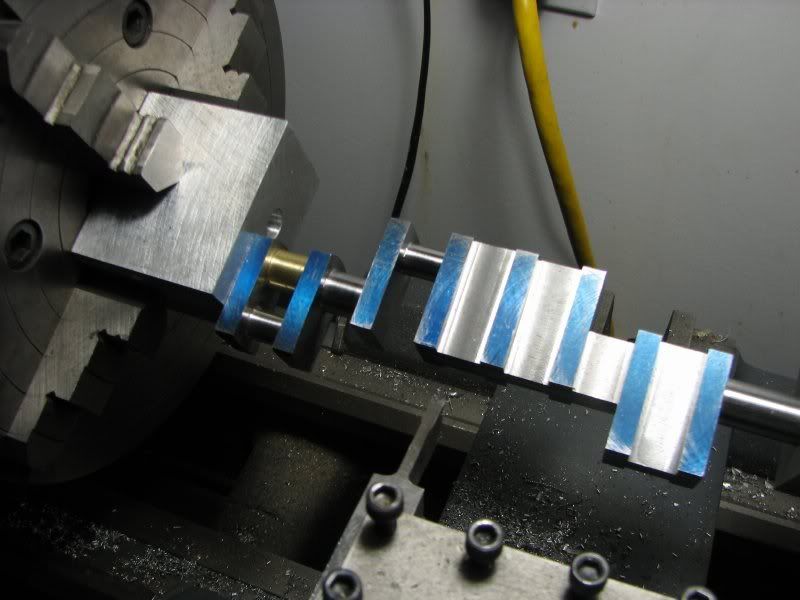
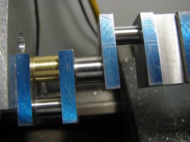
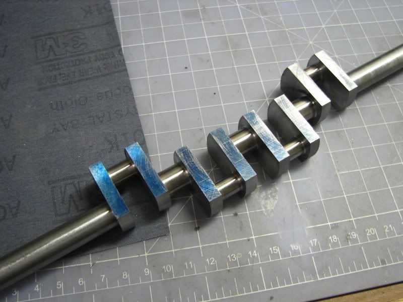
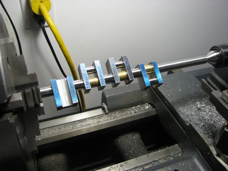
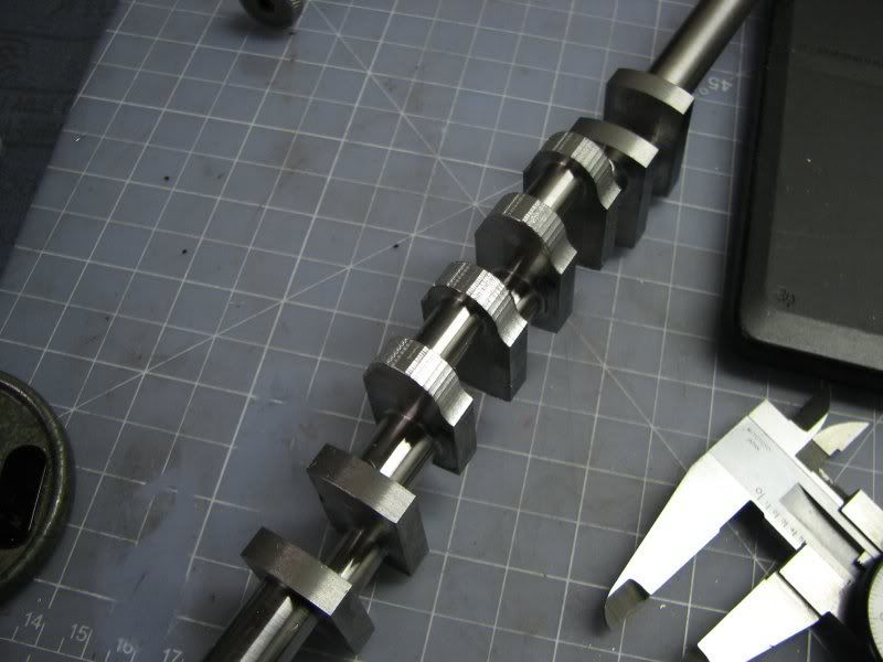
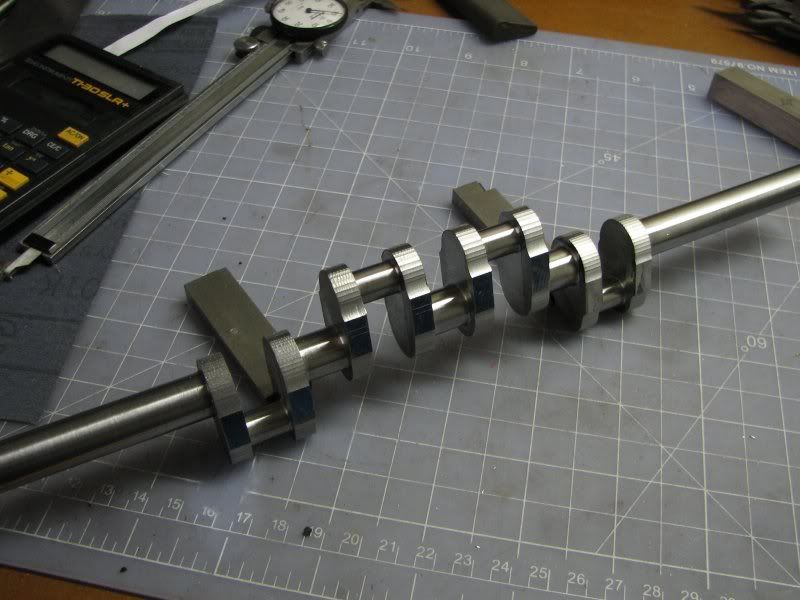
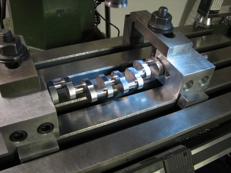
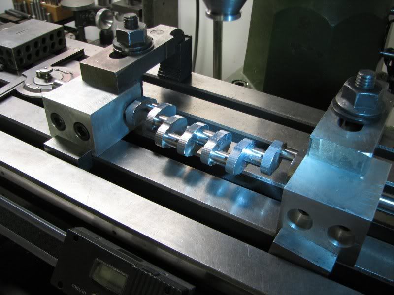
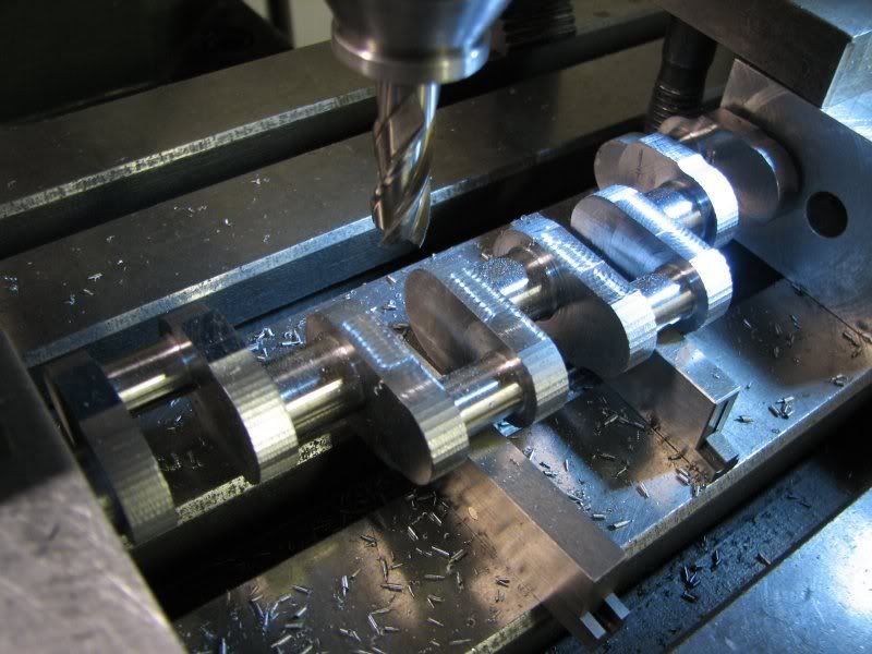
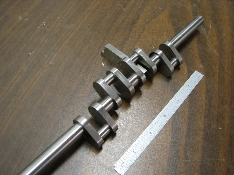
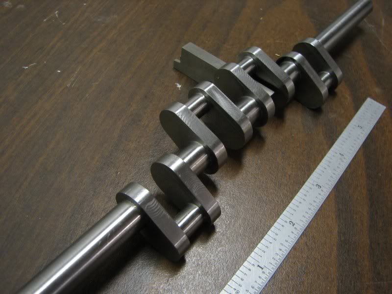
Gentlemen, the following will be a tutorial on machining a multi-cylinder crankshaft. In this case it's the crankshaft for my Holt tractor engine. I feel when making this type of crankshaft the most important factor is the machineablility of the steel. Although everyone has their favorite material, partly based on the equipment you have available, I now use 1144. I have made cranks from 1018, 12L14 and cast iron. I guess if a person had the right equipment 4140 would make a nice part. 1018 steel which is a common CRS is available as a flat rolled stock which expedites machining because you don't have to take a piece of round bar and machine it down to a rectangular shape. The problem with this material is that with cold rolling it builds up internal stress and when machined it likes to warp. Sometimes when you get the bulk of the material chopped off it stablilizes to some degree. 1144, commonly refered to as 'stressproof' is great stuff to work with. It has a higher machineability rating than 1018 ( 83% vs. 78%) and one of it's most endearing features is that it doesn't warp, or at least it's negligible. The bad thing is they don't make flat stock so you have to cut a piece of round down if that's your starting point. Most everyone here knows the virtues of 12L14 (leaded free machining steel) with a machineablility rating of 193%. I have made a couple of cranks from this steel with no adverse affects. The tensile strength ranges from 78,000 for 12L14 to 115,00 for 1144. What that all means to us as modelers I can't say. Our cranks are generally small and don't have great torsional loads put on them so the tensile strength is probably not as important as how well you can machine it. I don't know of anyone who has run their engine for a long period of time and then torn the engine down to check and see if the crank throws are still in the proper radial postion as when it was machined. That's not saying that nobody has, I just haven't heard anyone say they have. OK, enough with all this and on to the build. I started out by making a piece of rectangular stock to suit my requirements. I layed out the shapes on the stock and then started cutting. I first chuck the stock up close in my 4 jaw chuck, indicating it close and center drilling each end. After this I extend the stock far enough to cut one mainshaft. I leave a little material on it for the final setup. I then turn it around and do the other end. After this I mount the stock between centers and finish the main journals to size. I might add at this point that the procedures I use for this crank could be somewhat different depending on what size crank you're making and how ridgid it is. The first couple of pictures show the machining of the mains. I didn't take pictures of the center drilling as my explanation should suffice.
