You are using an out of date browser. It may not display this or other websites correctly.
You should upgrade or use an alternative browser.
You should upgrade or use an alternative browser.
A Compound steam engine idea
- Thread starter Maryak
- Start date

Help Support Home Model Engine Machinist Forum:
This site may earn a commission from merchant affiliate
links, including eBay, Amazon, and others.
J
JorgensenSteam
Guest
Bob-
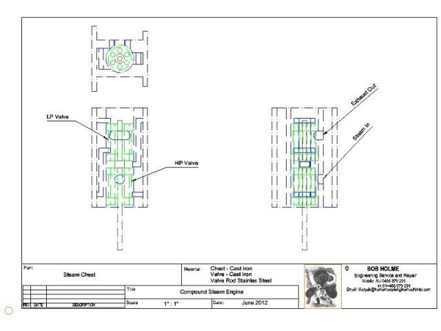
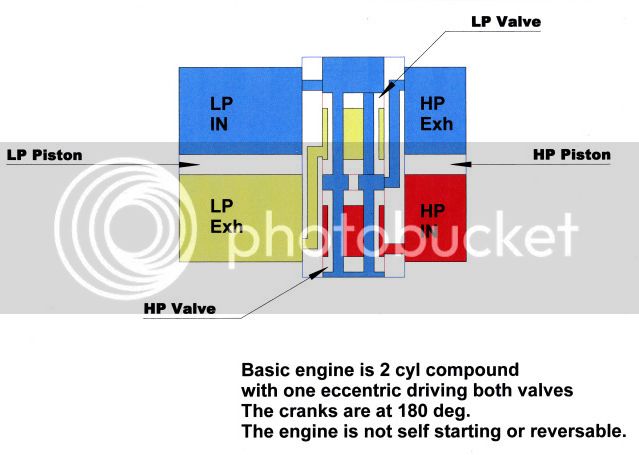
I am sure it is just me, but I can't follow the diagram at all.
Sounds like an interesting idea though.
I am sure it is just me, but I can't follow the diagram at all.
Sounds like an interesting idea though.
I got it, albeit the internals of the hollow spool valve are drawn in a misleading way.
The steam pipe enters in the red area while the exhaust exits in the yellow area
ignore the apparent mixing of receiver and boiler steam.
Tbe hollow spool has two or more ports drilled axially that meet near the center port
This valve will offer some heat to the receiver steam which should be helpful
Dave
Maryak
Well-Known Member
- Joined
- Sep 12, 2008
- Messages
- 4,990
- Reaction score
- 77
Dave,
Exhaust to atmosphere/back pressure system.
Dan and Pat,
Sorry my diagram is confusing. Now that I have the basics I will try and draw something more readily understood. Meanwhile try looking up Bellis and Morcomb engines as some of these used this system as well as the conventional two valves/eccentrics.
Best Regards
Bob

$59.99
Sunnytech Hot Air Stirling Engine Motor Model Educational Toy Electricity Generator Colorful LED (SC001)
stirlingtechonline
![DreamPlan Home Design and Landscaping Software Free for Windows [PC Download]](https://m.media-amazon.com/images/I/51kvZH2dVLL._SL500_.jpg)
$0.00
DreamPlan Home Design and Landscaping Software Free for Windows [PC Download]
Amazon.com Services LLC

$94.99
$109.99
AHS Woodmaster 4400 Maintenance Kit for Outdoor Wood Boiler Treatment
Alternative Heating & Supplies

$426.53
DM14 Engine Build Kit, Metal Engine Build Model Great Metal Material for Engineer for Factory
Easoger Official

$649.00
$699.00
FoxAlien Masuter Pro CNC Router Machine, Upgraded 3-Axis Engraving All-Metal Milling Machine for Wood Acrylic MDF Nylon Carving Cutting
FoxAlien Official

$188.98
TM NEXDYNAMI RE41157 Water Pump Compatible With/Replacement For/John Deere 6200 7400 6300 6600 6500 6400 7220 7600 7200 RE41157
VIVID MARKET CORPORATION

$160.35 ($1.43 / oz)
Replacement Combustion Chamber Kit, Burnham V8 and V8H, 1-6 Sec, 108136-01, 1129
Plumbing Planet

$99.99
AHS Outdoor Wood Boiler Yearly Maintenance Kit with Water Treatment - ProTech 300 & Test Kit
Alternative Heating & Supplies

$39.99
$49.99
Sunnytech Low Temperature Stirling Engine Motor Steam Heat Education Model Toy Kit For mechanical skills (LT001)
stirlingtechonline

$443.98
TM NEXDYNAMI AT29618 Water Pump Compatible With/Replacement For John Deere 1020 1520 2020 300 301 400 401 440 440A 480 AT29618
VIVID MARKET CORPORATION

$40.02
$49.99
Becker CAD 12 3D - professional CAD software for 2D + 3D design and modelling - for 3 PCs - 100% compatible with AutoCAD
momox Shop

$109.99
AmTech300 - Boiler Treatment Professional Strength (Rust Inhibitor For Outdoor Wood Boilers)
Alternative Heating & Supplies
J
JorgensenSteam
Guest
Ok, I am beginning to see it.
It is a section of a vertical twin engine.
The piston rods go out the bottom to the crank.
The pistons are shown in section as white rectangles.
My tired little brain is having to work on this one.
It is a section of a vertical twin engine.
The piston rods go out the bottom to the crank.
The pistons are shown in section as white rectangles.
My tired little brain is having to work on this one.
J
JorgensenSteam
Guest
Ok, here is my slant #2 on the "mystery compound" as I hereby dub this engine.
Picture a twin cylinder compound vertical engine with crank pins 180 degrees apart.
So when one piston moves up, the other moves down.
Now use two standard piston valves between the cylinders, and mount the valve stems to a common yoke that is operated from one eccentric only.
The valve on the right is inside admission.
The valve on the left can also I think be inside admission, and you need passages from the outside of the right valve to the inside of the left valve.
Since the pistons act opposite each other, then valve action can be mirrored (sort of), and operated off of one eccentric. If the engine did not have crank pins at 180 degrees, then you would need two eccentrics to time the valves correctly.
So in order to get the arrangement that Bob has above, stack the two piston valves in a common sleeve, make them into a single valve, and allow exhaust to run inside of it in a hollow space inside the thimble.
That is going to be a long valve, and the only way to change the timing is to make a new valve.
Makes for some unequal passage lengths, but certainly would be a functional engine.
That's my guess. (Wow, I am only 7.5 hrs behind steamer dave. Pretty good in my book, if I am right that is.)
Maryak
Well-Known Member
- Joined
- Sep 12, 2008
- Messages
- 4,990
- Reaction score
- 77
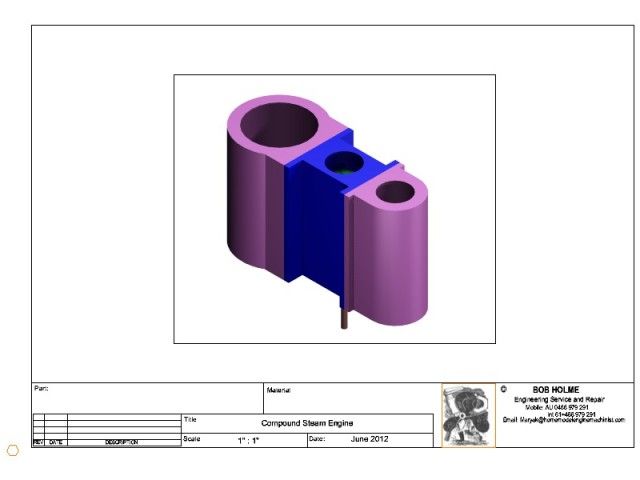
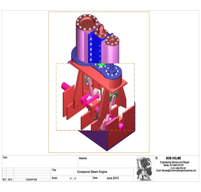
ironman said:OK Bob, now we need a nice 3D rendering of this engine. ;D
Ray
I hear you, like Xmas it's coming ;D


Dave,
Hope you can find some pictures of the Vulcan.
UNIcastings said:So in order to get the arrangement that Bob has above, stack the two piston valves in a common sleeve, make them into a single valve, and allow exhaust to run inside of it in a hollow space inside the thimble.
That is going to be a long valve, and the only way to change the timing is to make a new valve.
That's my guess. (Wow, I am only 7.5 hrs behind steamer dave. Pretty good in my book, if I am right that is.)
Close Pat,
You make two valves not one, that way they are independently adjustable using spacers on the central collar of the valve rod, just like the real thing.
Best Regards
Bob
J
JorgensenSteam
Guest
Ahhhhhh..........so very clever, those designers of old.
Dan Rowe
Well-Known Member
- Joined
- Feb 12, 2010
- Messages
- 594
- Reaction score
- 18
Bob and Dave,
I was looking for something else when I stumbled on the wiki entry for Vauclain compound.
The article has a link to the US Patent drawings.
http://en.wikipedia.org/wiki/Vauclain_compound
Dan
I was looking for something else when I stumbled on the wiki entry for Vauclain compound.
The article has a link to the US Patent drawings.
http://en.wikipedia.org/wiki/Vauclain_compound
Dan
Similar threads
- Replies
- 0
- Views
- 769
- Replies
- 5
- Views
- 755


![MeshMagic 3D Free 3D Modeling Software [Download]](https://m.media-amazon.com/images/I/B1U+p8ewjGS._SL500_.png)


