36x60x54 Twin Tandem Mill Engine

Home Model Engine Machinist Forum

Help Support Home Model Engine Machinist Forum:

This site may earn a commission from merchant affiliate links, including eBay, Amazon, and others.

Kawka777

Active Member
Joined
Mar 20, 2015
Messages
44
Reaction score
16
IMG_2337.jpeg
Hi All,

I am lucky enough to have a full set of original drawings for a Southwark 36x60x54 Twin Tandem Compound Engine. This engine was made for a 44” Reversing blooming mill that was in service from 1914-1924 before it was scrapped to be replaced by a DC motor.

I have all the detail drawings but I do not have any GA assemblies or anything to know how this engine should go together. I will be posting some sketches of the configuration shortly.

I am considering modeling the engine full scale to later scale it down. Do you all think that is worth doing or rather just scale it down off the bat??

I know there’s little to no plans out there for mill type engines, so I would be happy to share my scaled down models once I get there. I will definitely need your help in piecing this together, especially the steam valves and starter engine.

I will keep this thread going on piecing this engine together with 84 drawings!

Mike
 
I prefer to 3D model engines at full scale, and then create a model at some scale factor.
Easier for me to keep up with things that way.

If you have detailed drawings of parts, then we can figure out how they go together.

Here are a few prints that I have from old books.
Some are similar to your layout.

.

Fehrenbatch-22.jpg
Fehrenbatch-15.jpg
Walker-03.jpg
Unwin-09.jpg
Thurston-29.jpg
Snow-2j.jpg
 
I always design my models at the size they will be built. Although you can apply a scaling factor to a full size design you will then have to spend a lot of extra time going through it again to alter things such as stock sizes for piston and valve rods and all fixings will need adjusting for nearest common threads. Also you design needs to reflect the way you will be making it, no point in drawing the original casting if you are going to have to fabricate from several parts, even if you do cast will it be practical to cast all the detail that the original had? If not little point in wasting time drawing it at full size.

Then there is the simple fact that what is possible at 12" to the Foot becomes impractical at 1/2" to the foot which is the biggest likely sort of scale you will be building at eg 1/24th scale.

You would do well to look a the various forums for build threads of the Southworth tandem compounds which were available in several conforurations from casting sets. There are several build son MEM forum. Also I think Julius De Waal has his version of this engine drawn up for barstock.

https://www.modelenginemaker.com/index.php/topic,7688.0.html

https://www.modelenginemaker.com/index.php/topic,9540.0.html

If you search for Porter & Allen engines then you should get an idea of what they looke dlike as they were built by Southwark
 
Last edited:
I guess it depends on what you are trying to achieve (how you initially model it).

If you are trying to rigidly adhere to the look/feel of the original engine, then you may want to model it full size and then adjust things internally, without changing the exterior of the engine.

If you want a free-lance sort of build, then just model it as something that looks approximately like the original, at the scale that it will be built.

I would say in general the larger the original engine, the more difficult it is to built a scale model, since many parts get too small/thin.

Some folks build static display models/dioramas, and they want the scaled model to look exactly like the original, and so they use full sized dimensions.

There is a bit of an art to scaling an engine and making a functional model, while maintaining most/all of the original engine features.

A balance must be struck between time available for the design/build, and trading off complex features for something that is easier and more practical to build.

In the old days of hand-made wood patterns, it would have been tedious to include a lot of fine detail.
With modern 3D modeling programs, and 3D printers, one does not really need to trade off much from the original design.
It is pretty easy these days to get away from the sometimes old-days traditional "lumps of metal" castings, and cast a lot more detail, with castings that are not oblong/egg shaped, and are at near net size.
.
 
Last edited:
Before you do anything you need to think about the following

Scale
As I mentioned above with an engine this size you are likely to be looking at 1/24th scale but 1/32nd would also be worth considering and may be easier for calculations when reducing full size down to model

Practicality
This relates to scale in many ways. You need to consider what are parctical sizes for you to machine, often the swing of your lathe dictates the size of the flywheel and everything else has to relate to that. However on engine slike this you need to think about displaying, storage and transport. At a minimum you are gouing to end up with a base of something like 2ft x 3ft and of quite a weight. And at the other extream, what is the smallest thread you want to use. At 1/32nd scale those 2" studs and nuts holding on the cylinder covers suddenly become #0-80 (won't suit Pat)

Construction methods
The main two choices are to make patterns and have castings done or cast your own. The other is to use a mix of cutting from slide and fabricating. The design will need to take this into account for example you can model the exterior exactly to replicate the original but you would be wasting time modeling all the cored in passages when you will be milling and/or drilling them if not using castings. Even then it may not be practical to cast some of these internal feature seven if you do opt for castings due to the fact you are making a much reduced model rather than something like a 1/2 or 1/3rd scale hit and miss engine.

Ability & Resources
Have you designed a model before? if not it may be better to start out with something simpler as there are a lot of design decisions that need to be made that only experience of designing and for that matter making other models will have given you. Do you have the workshop eqipment and tooling to actually make what you design. Can you afford to get bogged down in making tooling, getting old machines up and running, learning to cast, etc if that is going to be needed to make the model

Time
How much do you have? Building a model of this engine is going to need a big commitmentthe to time both in the workshop and also at teh design stage. This is one reason I suggested designing straight off at model size as you will not be doing a lot of the work twice

Design Method
Your pencil sketch of the layout suggests you may not have 3D or 2D CAD which will be a disadvantage, and certainly will if you design full size first as unlike CAD which can scale at the click of a button you will have to draw it all again.
 
Thanks JasonB for the realistic project grounding!

The goal for me in this project is piecing this engine together to understand how it works in the form of a scale plan that I can build in the future. Right now, I do not have the skill to physically build this engine and I am pretty new to the model engineering world. I was more into building jet engines until recent. I definitely want to start machining on a PM research or Stuart casting kit get to get my feet wet.

I work at a steel mill that still uses an original William Todd 1000T Steam Shear, which i am involved with almost on the daily, so hence the new obsession with steam started lol.

I built my jet engines on a 10” atlas lathe and learned a ton, so I can hold my own there. I have a Burke No3 mill that I have not had a good excuse to learn how to use yet. I definitely have a ton to learn about machining before embarking on this project.

As far as modeling, I am fluent in Fusion360, Inventor, and most other 3D modeling softwares, so drawing this will not be an issue. I have the free version of Fusion360 at home, but this has limitations on producing drawings and sharing them. Do you all use anything else?

Time for me is the issue. I have a ton of projects but I am generally good at finishing them. I will be done with my kitchen remodel in a month, so i am excited to get back to doing what i really enjoy. Working on designing this engine is more of a "I do not feel like actually standing and working on something" project that I can turn back to in the evenings. I try to do stuff like this rather than watching TV. As much as i want to model this full scale, i know it will take me ages just to model the castings, and for what purpose other than having to redo it later to scale it down. Those old drafters made beautiful drawings, but they are definitely not user friendly.

I have not designed an engine before, but I am the type of person that only learns by diving in head first on a hard project lol. Once huge bright side for me, a beginner, is this engine uses sliding spool valves rather than the Corliss valve gear. I do not think i would go after this engine if it had Corliss valves like the ones GreenTwin shared above.

Making this engine to scale from the start makes sense to me, with the goal of making it as close to original looking as I can.

The foot print of this engine is 54' and width is about 20', not including the gear train to the pinion stand for the mill.
1/24 scale puts me at 27"x10" with a 1.5" HP piston and 2.5" LP piston.
1/32 scale puts me at 20"x7.5" and a HP piston of 1.125" and LP piston of 1.875".

Mike
 
I worked on making a 3D model for the steam ship Mississippi, and there were 50 (+) original drawings from 1840.
I think the cylinder bore is 120".

Old drawings can be difficult to use, due to light lineweights, bad condition, wrinkled/warped pages, missing pages, etc., but they give a very accurate model if you use them carefully, and weed out errors as you go.

It is important to start with one part at a time, and verify all the dimensions for it; then find the mating part, and be sure that model mates perfectly with the previous model, etc. One has to be very methodical.

I use Solidworks.
Alibre is more than capable though, as JasonB has mentioned in other threads.

In Solidworks, I mate each part, and verify correct rotation before I proceed to the next part.
If the part does not fit in SW, it will sieze and not rotate.

Image24 (12).jpg


Image20 (2).jpg


Image43 (5).jpg


Image6 (16).jpg


Image22.jpg


Image49 (4).jpg


Image61 (5).jpg


Image81 (2).jpg


Image88 (3).jpg


Image90 (2).jpg


LOWER-CYLINDER-04.jpg
 
Last edited:
Greentwin,
Very impressive model. It makes sense to build the assembly on the fly to check the parts.

Do you use a license version of SW? I see you can get a free version but I fear it will have the same limitations as Fusion360 and Free Inventor.

If you use a free version, do you get the fastener databases? Thats another downside of autodesk free.

I never heard of Alibre until now. I just watched some videos on it and it seems promising, especially for $200 lifetime purchase.

Mike
 
I have a licensed version of Solidworks, 2011, perpetual license.
One problem with SW and perhaps some other software is version compatibility, but I can exchange blocks (non-editable) via one of several file exchange formats.

I purchased SW due for work, and since it did not have an annual fee.

As I understand it, Alibre has improved a lot since it was introduced, and it seems to be a good choice for hobby work.
I have not seen SW do anything that Alibre can't do, and you may actually get more features in Alibre.

I am not sure if Alibre has "Motion Study" in the base package, but SW does.
SW does not have "Render" in the base package, and so I don't render my models.

I learned the hard way that if you don't verify the fit/movement of each 3D part as you create it, then it becomes a needle in a haystack affair trying to figure out why the engine won't run in simulation.

It is pretty cool that an engine from the 1840's can be brought back to life using these programs, and then modeled.

.
 
You can download fasteners and other parts from the McMaster-Carr website.

I download basic fasteners in 3D, and then modify the head to look like old-style fasteners.

.
 
On a model like that you are not going to be wanting to use much in the way of stock UNC and UNF fasteners so better to create your own using the smaller hex size model engineering fasteners which is likely to just be a range of nuts as they would have been using studs and nuts. Apart from looks on the 3D model there is not really much need to include all the nuts and studs just align the holes in the assembly and it won't slow things down like having a couple of 100 nuts and studs will. It can be useful to add the odd one just to check they clear adjacent edges etc, I have a folder where I have modeled all the common ones I use and just insert them if needed.

https://godshallscustommachining.com/collections/frontpage/products/model-hex-nuts

You don't have to assemble each part as you model it as any assembly problems will show when the part is added to the assembly and show up at that stage. I tend to draw a related group of parts and then add them to the assembly though it is also good practice to have sub assemblies and then bring them together as one main assembly

The ability to view sections of an assembly is very useful as you can watch all the parts as they move and check things like the piston does not hit the cylinder end covers or the conrod does not hit a crankcase or crosshead guide.

I have used Alibre for many years and pay to get the regular updates.
 

Attachments

  • fixings.JPG
    fixings.JPG
    76.4 KB
  • Rocker 2.jpg
    Rocker 2.jpg
    327.7 KB
  • Rocker 1.jpg
    Rocker 1.jpg
    316.6 KB
  • DSC03967.JPG
    DSC03967.JPG
    3.2 MB
The problem with not checking each part in the assembly as it is created is that if you have a dimensional error in one part, then that error may propagate/domino across multiple other parts, in which case you will then be revising multiple parts instead of just one once the error shows up in assembly.
.
 
It works for me and I get the designs complete and the engines made.

Your unusual method of using 2D drawing from one program and importing to the 3D model also means you can't make full use of Parametrics where the sizes /features of one part can be related to another so change one and they also change on the related parts.

There is also the fact that of several parts modelled at the same time only one or two may have something that affects the motion of the assembly so no need to keep going back and forth for each one
 
Last edited:
The complexity of the design may affect the approach too.

I don't like to get too carried away with parametric linking, because again you can automatically propagate errors across multiple parts, instead of compartmentalizing the error to a single component.
I prefer firewalls, so to speak.

There is more than one way to approach/do a 3D design, and we all have our favorite methods, as you can tell from these discussions.
You have a buffet of ideas/approaches presented here to choose from.

As JasonB alludes to, tailor your approach to what best suits the design you plan to build, using the methods that best suit you.
We can only describe how we do it individually.

I really enjoy the power that 3D modeling has added to the hobby, especially when you couple that with either 3D printing or CNC machining patterns.
3D modeling has really taken this hobby to a new and exciting level.
.
 
Last edited:
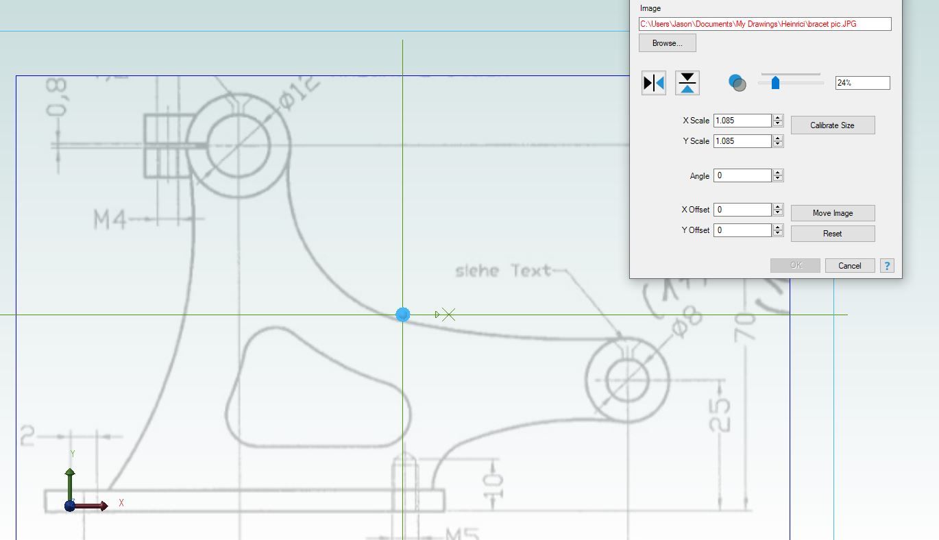
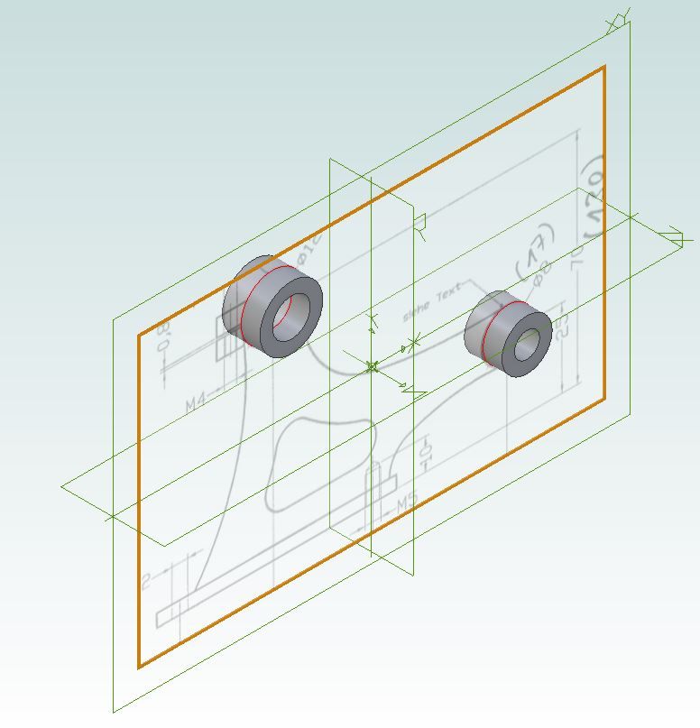
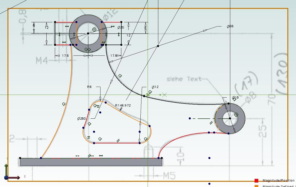
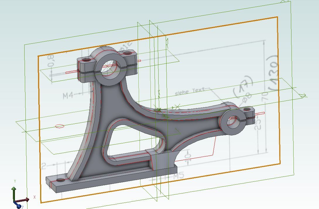
Another useful feature which Alibre has, others may too is the ability to import an image be that a photo, patent drawing or in your case a scan of part of the drawings. This is very useful when replicating castings as most drawings will only dimension the machined surfaces so it is left to you to work out the cast surfaces.

This example shows the drawing
pdf1.JPG


I then drew the two bosses, positioned to the drawing dimensions, ID as dims but OD just what overlaid the lines
pdf2.JPG


I then drew the cast outline to best overlay the lines on the imported print
pdf3.JPG


Each feature was done in a similar way to build up the "casting"
pdf4.JPG


Came out OK on the model, all fabrication or cut from solid


DSC04081.JPG
 
That is a nice feature !
I have never been able to do that in SW.

I use that frequently in AutoCad for 2D work.

As JasonB mentioned, I often draw a 2D sketch in Autocad, and then import that sketch into Solidworks.
I much prefer doing 2D work in Autocad than SW.
For me, complex sketches are infinitely easier to create in Autocad.

Some folks have told me they prefer sketching in SW.
It is a matter of what works best for you.
There are many ways to leverage the features/power of today's 3D programs.
.
 
Last edited:
That is a nice feature !
I have never been able to do that in SW.

I use that frequently in AutoCad for 2D work.

As JasonB mentioned, I often draw a 2D sketch in Autocad, and then import that sketch into Solidworks.
I much prefer doing 2D work in Autocad than SW.
For me, complex sketches are infinitely easier to create in Autocad.

Some folks have told me they prefer sketching in SW.
It is a matter of what works best for you.
There are many ways to leverage the features/power of today's 3D programs.
.
I am definitely one of those people. I learned on autocad in high school but once I learned inventor and creo in college, I never went back to autocad.

I am going to give Alibre a shot for this. I use the autodesk suite professionally at work but the free versions are limiting at best. I have been hoping for a good alternative and maybe $200 for Alibre is the option. I am not sure if it has motion assemblies, but if I really want to go down that road, I can import the models into fusion360. If I was going to model for the sake of making the 3D model, I would animate, but since I’ll scale it down to build, I should be able to work with the sections as JasonB does.

I am actually in the process of animating the steam shear I mentioned before. The throttle valve and steam cut off valve is insanely complicated to explain to people, so an animation of the cut cycle would be gold.

Greentwin, i totally understand the “isolation” you do with your parts. Sometimes I design using constraints from assemblies for new parts, and often I find something wrong and have to go back and figure out what part I am driving the design off of.

I’ll download Alibri tonight and start playing with it.

I think I have a good “foundation” to start with. Studying the detail drawings, I have the bed plates, cylinders, cross slides, connecting rods, crank, and mains all put into a GA hand sketch.
I bot Alibre a couple years ago. I went from ACAD 2000i Architectural, which does mechanical just fine, to Alibre. At first I was confused--it seemed difficult, only because I had used ACAD for about 25 years. My biggest problem, now seeming trivial, was that to start a drawing one has to clik on the 2D plane you wish to start on in order to start your drawing. I use Alibre almost exclusively now.
 
You can get all the parts in an assembly to move easy enough in alibre.

 
You mentioned that this engine has a barring (or starting) engine. That would be a good starting point if you can make a model of that then you are likely to be able to make the rest.

This is another thread from MEM forum, although 1/16th scale the original has 18" and 33" cylinder so about half the size of your project, about half way in he shows the barring engine being made which ends up about 3" tall. Worth noting how he dealt with the steam passages ( post #127) which illustrates what I said about designing it to be made not designing as per original and hoping it can still be made at 1/24th or smaller.

https://www.modelenginemaker.com/index.php/topic,2154.0.html

The amount done over the time span of the thread is another example of what time it can take. Also don't put it off as a retirement project as you may never get to do it. I know someone who could not wait to take early retirement and they built up an extensive workshop and stash of casting sets in advance only for health issues to get in the way. Over the last two years all they have been able to do is what I could have done in a weekend and they are not even 60.
 

Latest posts

Back
Top