260 Brass Metal Spinning Project

Home Model Engine Machinist Forum

Help Support Home Model Engine Machinist Forum:

This site may earn a commission from merchant affiliate links, including eBay, Amazon, and others.

sunworksco

Rocket Man
Joined
Nov 20, 2010
Messages
242
Reaction score
13
I need help in how to go about having some 260 brass that is 1/8" thickness x 1/4" width flat rings cut from a 12" x 12" plate.
The rings will be 10-1/4" OD and progressively smaller.
I am metal spinning a torpedo hull that is 47" length and will have 5 sections.
The rings are for sectioning the hull together in one piece by silver-soldering the rings in between the sections.
Is it possible to machine the outer edge of the brass rings as to create a shoulder to create a bridge between the spun brass sections? This could index the sections together for better alignment.
Regards,
Giovanni
Hull-Final-Arc-outline.jpg
 
As the rings won't be seen you could mark out your rings and then drill a few holes into them in non critical areas. Mount a piece of MDF or ply onto your faceplate and then use the holes to hold the brass to the board. You can then turn the OD complete with any steps required and then trepan the ring off the main sheet, keep working like this with each ring getting smaller.

If your lathe cannot swing that big it should also be possible to fit the MDF/ply onto a rotary table and use a milling cutter to make the rings and shoulder cuts.

You will need to rough cut the plate into a circle to start with using a bandsaw, jigsaw or even just knock the corners off with a hacksaw.

Make sure you have holding screws in both the ring and the central part of the plate so the work won't fly off when separated.

Jason
 
Thanks Jason,
How thin can I machine the "Tee" section on the outer edge of the rings, without ruining it ?
Regards,
Giovanni
 
1/16" would be easy and have plenty of strength and I should think 1/32" quite possible.

Jason
 
Maybe of interest to you.

I have a customer who welds aluminium road tankers (for gasoline) out of 5mm plate by the same method of using a joining "T" which he rolls into rings from extruded stock.
.
The whole assembly is tacked together on a jig and then the entire tank (±1.6m x 1.4m elipse x 12m long) is loaded between faceplates and robotically MIG welded

FYI

Ken
 
That sounds very smart.
If I can roll some 1/4" 260 brass tee, that would be the greatest!
Maybe use some scale model train brass rails?
Thanks,
Giovanni
 
That sounds like an interesting project. What will the thickness of the shell be where the rings are placed? If you want to roll them it would be easier if you can manipulate the aspect ratio of the part between the shell plates so that it gets bent the "easy" way rather than the "hard" way. A flat, stubby T rather than a tall skinny one. Also you may want to ask if the inner part of the ring needs to be continuous. I'm thinking a narrow strip with slices part way across the narrow dimension and the bent alternately right or left. If the height of the resulting upright web is lower than its thickness (Or nearly so) it would be easy to bend into a round shape. It would not offer the stiffness you may be looking for from the machined pieces untill soldered together. I think it's going to be challenging to keep everything on axis without some kind of really stiff tube down the middle to hold everything in place. Maybe it should be made in two halfs like a clamshell. Make one half fixed to a flat surface and then a second one and the bring the halfs together along a longitudinal seam around the mid line either side to side or top and bottom. Guessing that this is going to be some kind of vessel, that might make getting into the works easier too.
 
The submarine shell will be 3/32" thickness.
I think that if I cut the tee section down to a tall enough measurement, just slightly shorter than the shell thickness, as to allow indexing in-between the hull sections that it will provide enough strength. I'm thinking that I can mill a 180 degree radius slot in a block of steel to bend 180 degree brass train rail and then solder those in-between the hull sections.
The metal spun sections and indexing rings will be clamped on a hemispherical jig for hard silver soldering.
Thanks,
Giovanni
 
I would shoot to make the rail pieces stand proud of the outer skin and then dress them back to flush after soldering. Otherwise you will end up with a lot of places that will be lower than the skin surface and it will be tedious to fill them in. I think I would try bending the rail on a wood form. Easier to make and should be up to the task unless you are making a fleet of something. Also the brass rail will be pretty work hardened from the forming process, so you will be needing to figure out how much spring back you get and adjust the form accordingly. You might want to consider annealing the rail material before you bend it. That will reduce the springback a lot. You also might want to look at some kind of three roll ring roller that allows you to adjust the position of one of the rolls to get to the size you want. Harbor freight has a couple (big and small) and some slip roll setups have groove for rolling rings although you might have to make some mods for the odd cross section of the rail.
 
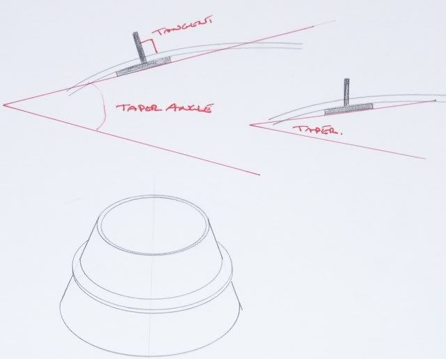
If you do go for rolling you will need a set of rolls that can do tapers, you may well be hard pushed to get enough taper for the rings towards the ends.

Jason
 
Jason,
I'm not understanding the taper meaning.
Maybe I should just use a 12" x 12" x 1/8" 260 brass plate and mill the rings?
Regards,
Giovanni
 
If you just rolled (or machined) a flat tee ring then it would not fit the curve of your torpedo.

The top left shows how you would need to roll the section, this gives a tangental leg, the sketch on the right shows how it could be turned to put the leg at right angles to the central axis of the torp' The cone shape at the bottom is an exagerated view of what a complete ring would be like.

PICT0202.jpg


Jason
 
In my head, the "T" sections are as you show at the upper left. It would be a real PITA to do the lower right picture and, since the protuding flange will, I presume, be removed it's probably not worth the trouble. I agree with your observation about the "T" section not perfectly fitting the curve of the plates and if we were talking about a full size submarine with 6" thick plates the "gaposis" at the joints might considerable. With plates that are only 3/32 thick, I think the "gaposis" will be lost amid the other interesting stack-ups that will occur. BTW the HF geared ring roller is about $70 and LOOKS like it would be pretty easy to mke "T" section rollers for it. One potential advantage of machining the rings out of plate might be that you could leave the center of the plate just barely attached to the ring and then remove it after soldering. Of course getting the last one out would be interesting since you (or someone) will have to be inside to get at it. Don't forget the door!!!
 
Going a little crazy, here!LOL! :big:
Now I understand the tapered ring thing.
Maybe I am going down the wrong path?
The steel spinning mandrels are very precise for spinning the 260 brass blanks so the hull section butt joints should mate up perfectly.
What if I just butt-joint silver solder the hull sections together?
I am building an RC 1/12Th Scale USS Holland submarine and the interior hull is flooded. A water-tight compartment pipe will protect the electronics in the hull interior.
Regards,
Giovanni
 
You could just use some short bits of flat brass say 1/2" square, 1/16" thick, fix about 8 of these around the joint held in place with small brass screws - 10BA, you would need to drill and tap them. This would hold the sections in place as you solder them, the screw heads could also be soldered in and filed flush on completion.

I don't think you will just be able to butt joint and hope to solder, the metal will move about as you solder it due to expansion so you need something to keep it aligned.

J
 
Jasonb beat me to it I was about to suggest the same thing - but I was going to suggest you spin a conical ring to place on the inside.

Use brass cheesehead screws to loosely hold the parts - these will become soldered in and can be dressed off later.

I am also concerned about the amount of distortion that might come about if you try to work around the seam - as one side cools it pulls the other side open.

I would suggest you mount the (fluxed) assembled sections like a spitroast and rotate (have someone do it for you) apply a large flame to one side and when up to temperature you apply the solder on the opposite side with a smaller flame. Rotate rapidly during heating (to get it evenly heated) and obviously slow down to as fast as you can perform the soldering once it reaches temperature.

At this point it might be an idea to remove the large burner and have a (third) person silver solder the opposite side - it will go twice as quick and minimise the scope for distortion.

You may also need to cover the shell - other than the seam - with an insulating blanket (ceramic fibre mat or similar) otherwise you are going to have a massive heat sink - it will also be unpleasant working close to it as well.

Personally I might consider doing this in TIG welded stainless or aluminium.

Ken
 
Yes to the comments above. I think you are going to need some axis around which to assemble the sections and something to keep the spun sections in the proper location relative to that axis. Thermal distortion while brazing is a real important consideration. If you have steel spinning mandrels, this is not a low budget exercise so you might want to explore furnace brazing the whole thing at once through a commercial brazing service. This would require some fixturing to hold everything together during the process. Alignment tabs or rings as you originally thought would be good. I don't think there's any future in assembling it it free space w/o some fixturing to hold things in line.
 
cut the ends of the tube sections so each fits into the next one. a skim cut on one end of the inside of the tube, and a matching cut on the outside of the mating piece should allow them to fit together with no seam.
 
Kermit said:
cut the ends of the tube sections so each fits into the next one. a skim cut on one end of the inside of the tube, and a matching cut on the outside of the mating piece should allow them to fit together with no seam.
Kermit & Friends,
I like the skim-cut edges of the sections best.
This would allow me to do my own silver soldering and not use a commercial oven, although a commercial oven would be fool-proof.
The tricky part is chucking up the sections on the lathe to get a precise and uniform fit.
Thanks,
Giovanni
 
If you do decide to go the commercial route I would suggest you find someone with induction heating facilities.

Typically you (they) would make a heating coil of two turns of 1/4" or 3/8" copper tube - this is placed over the part which has been prefluxed and a snap ring of silver solder rod placed on the joint.

The tubular induction ring is water cooled and is generally connected to the induction supply with standard compression fittings.

The part is rotated for even heating - the heating is localised and depending on power available takes a few seconds.

This is typically how production brazing / soldering is performed.

This will require a 20 - 40 kW low frequency (10-20kHz) supply.

If you can locate a supplier / manufacturer / owner of induction heating equipment near you you might be able to persuade them to do the job as a demo / advertising / sponsor - whatever.

P.S. - Kermit - great idea.

I love seeing the solutions that turn up from "brain-storming" on the forum.

Ken
 

Latest posts

Back
Top