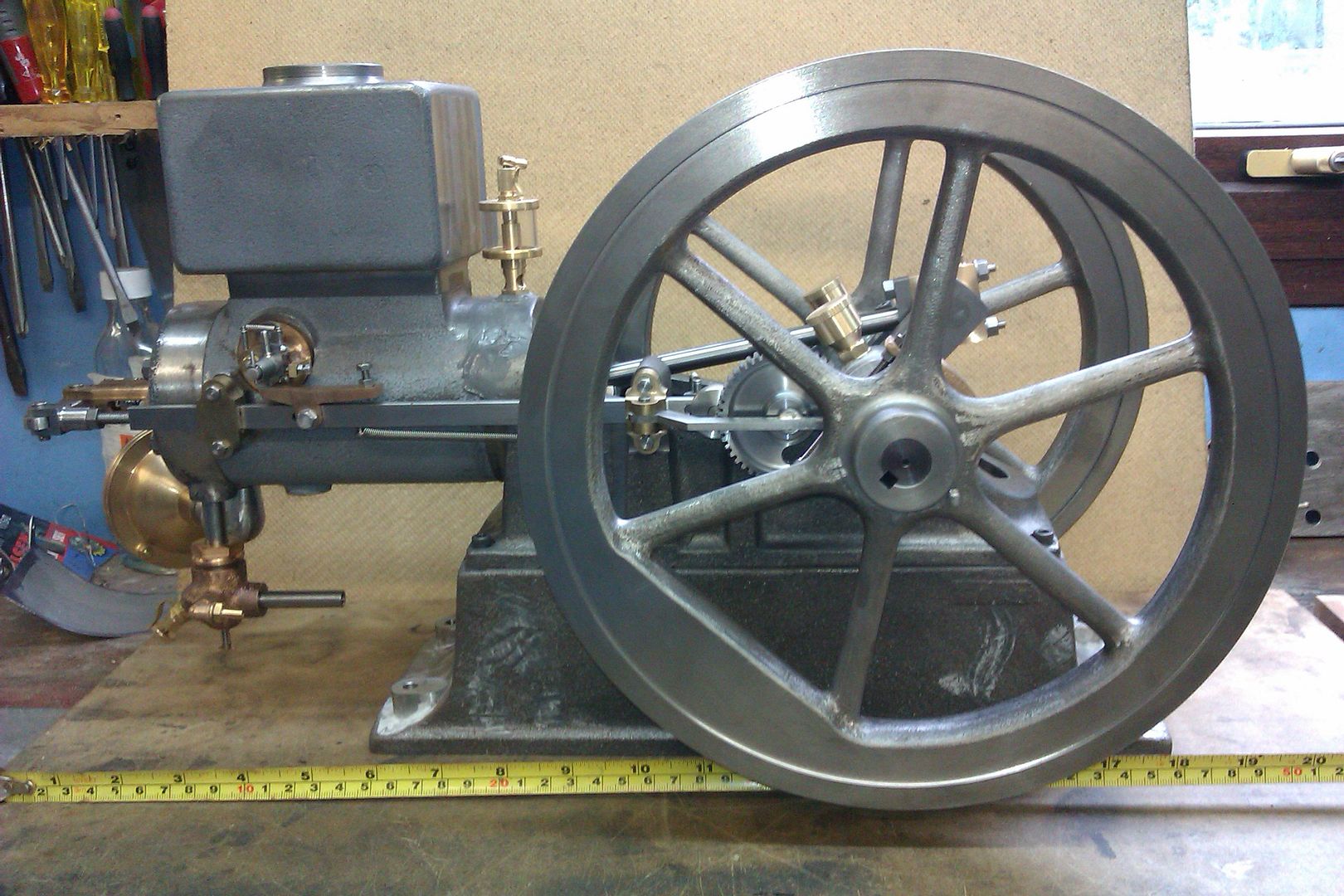
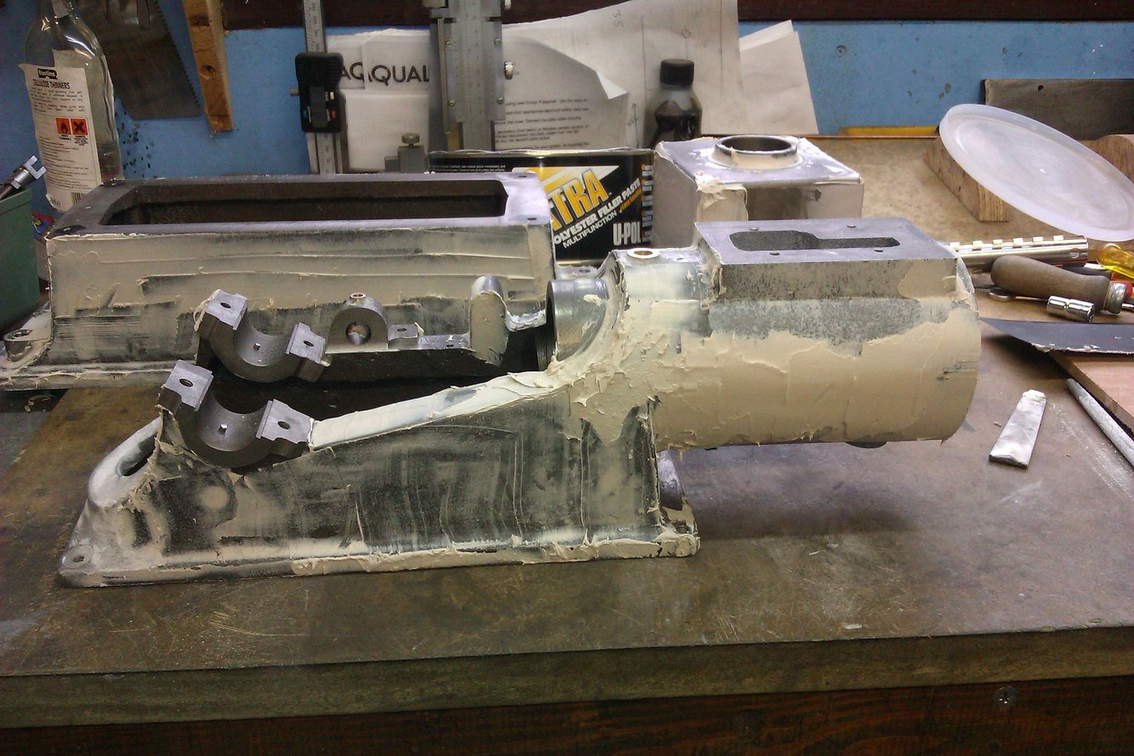
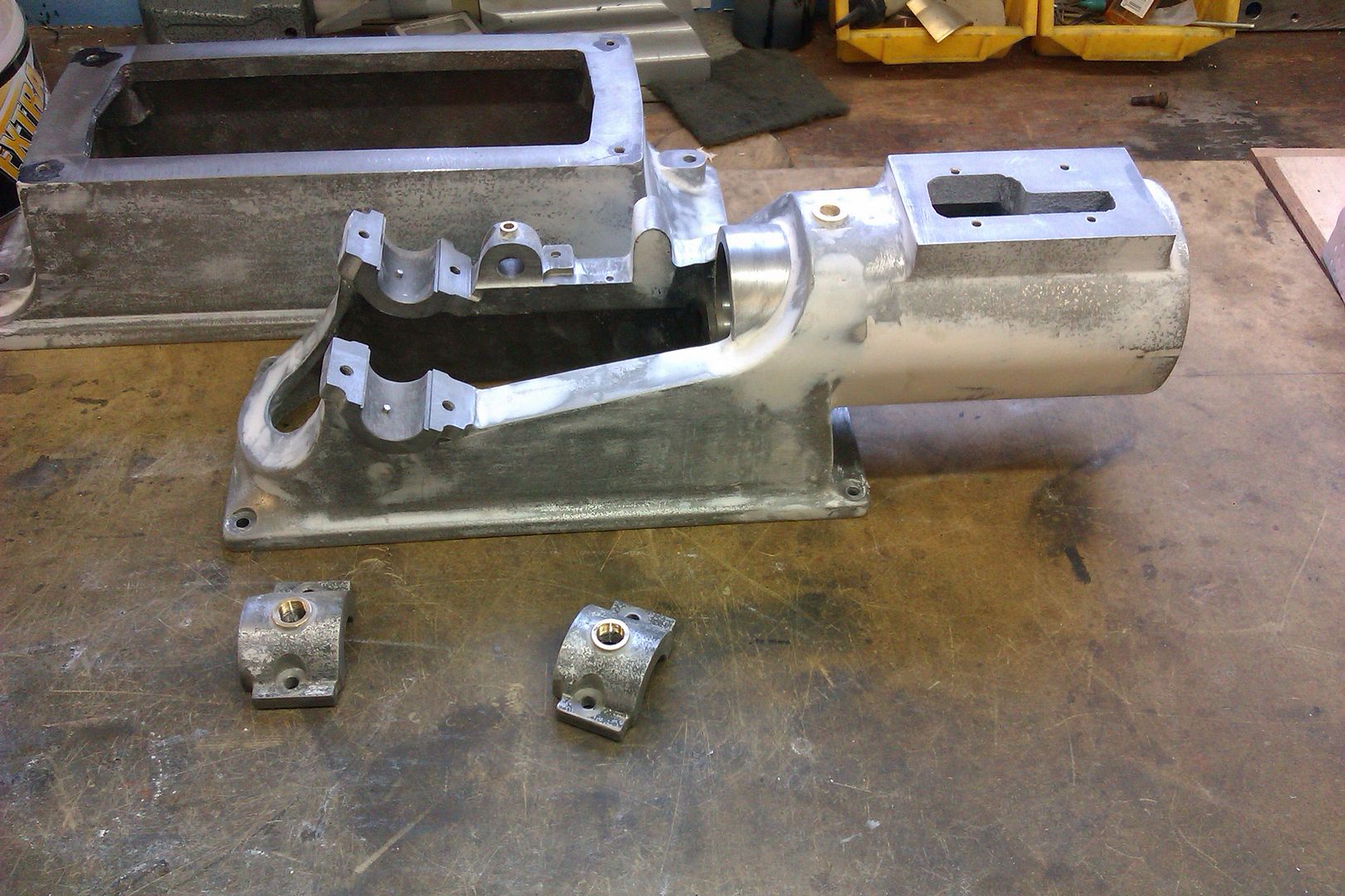
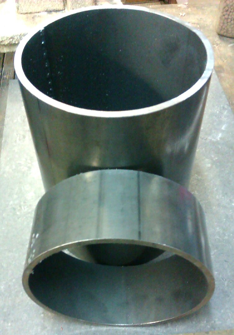
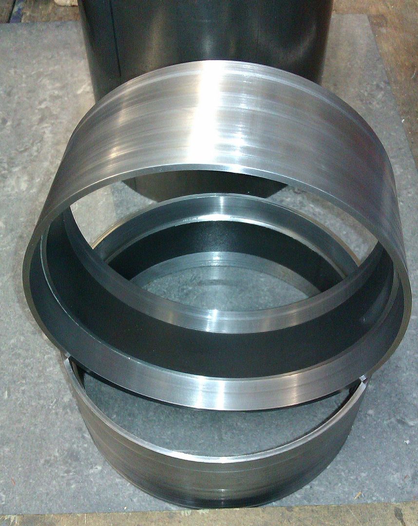
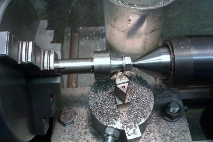
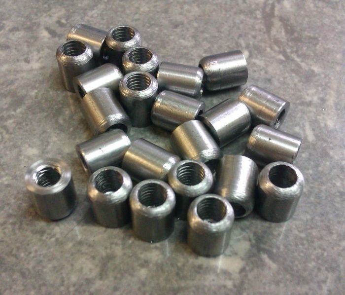
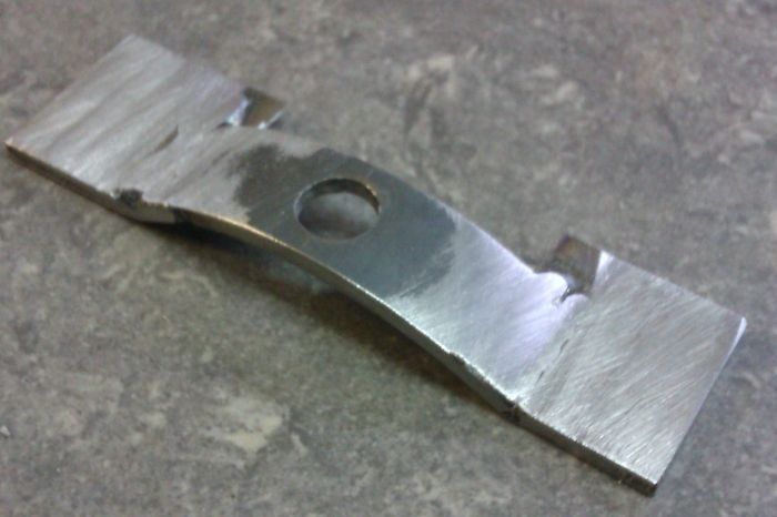
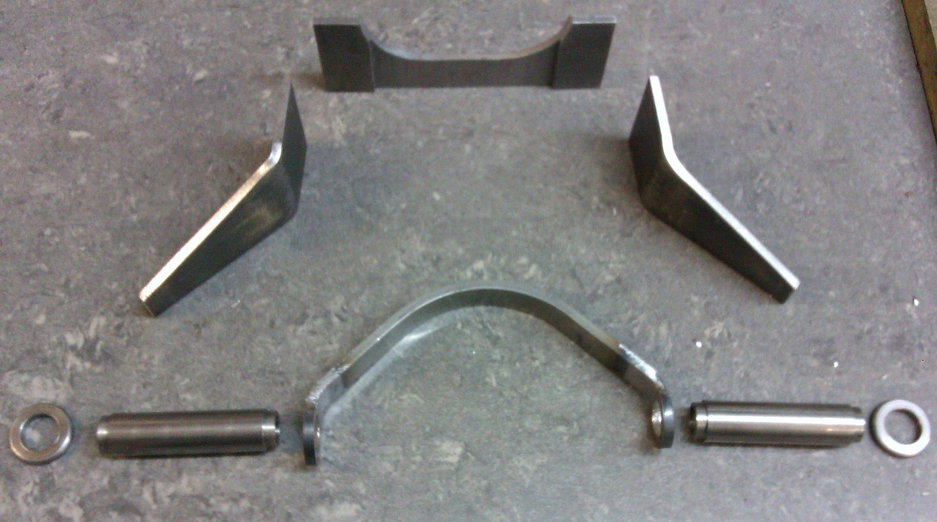
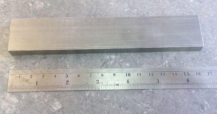
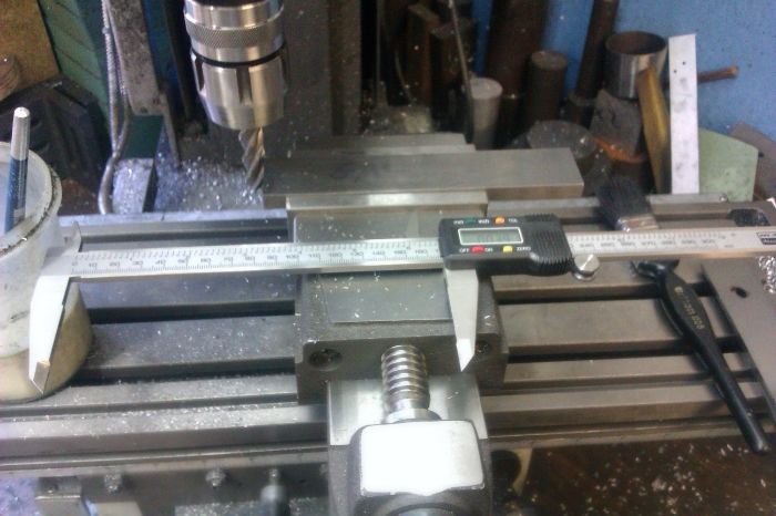
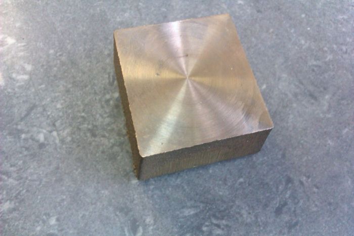
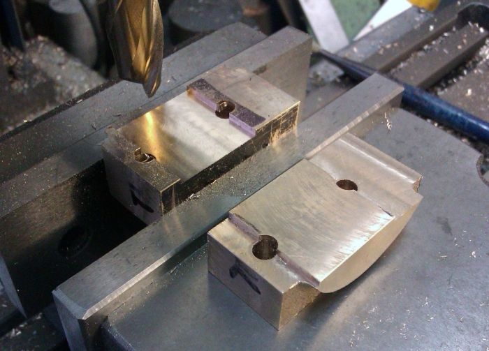
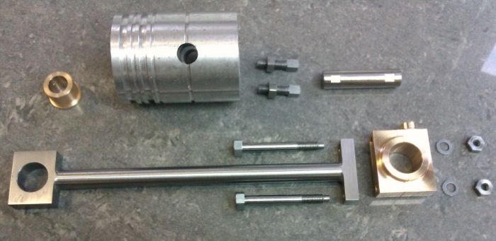
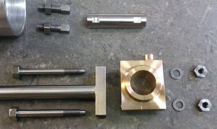
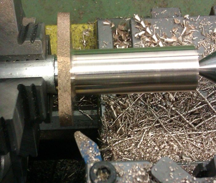
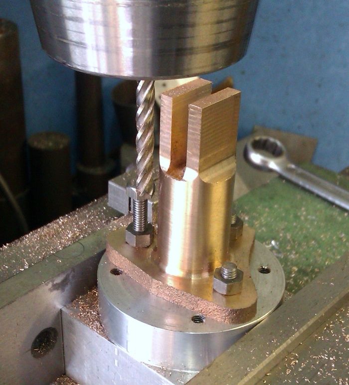
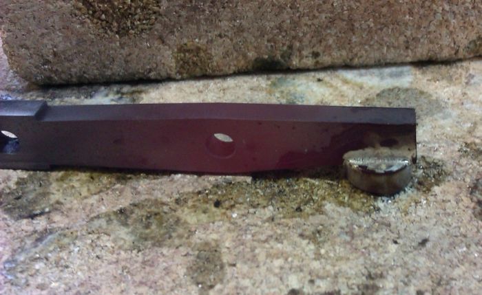
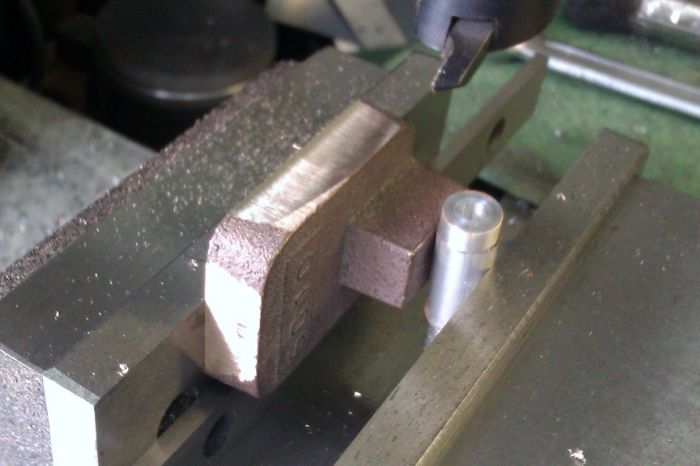
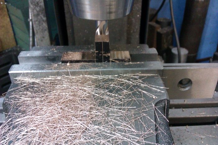
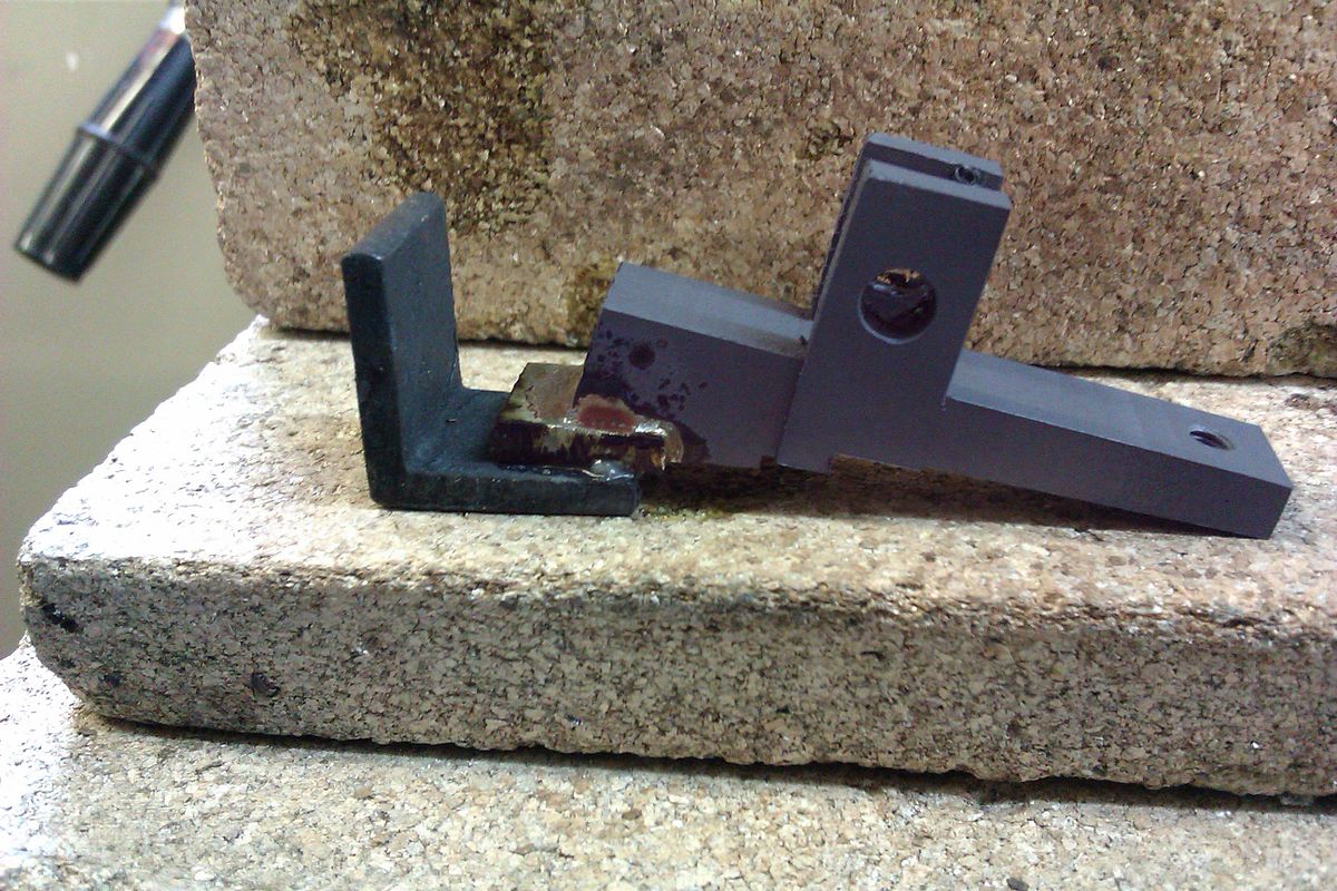
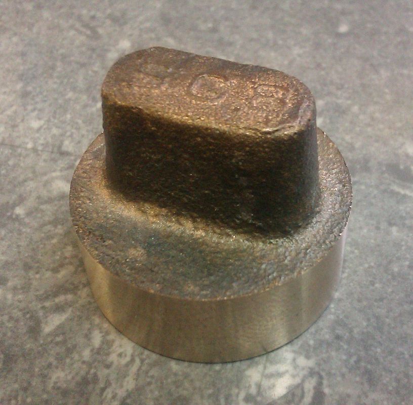
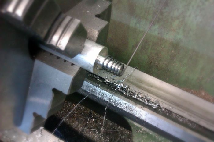
With the crankshaft and flywheels done all that was stopping me being able to play with the engine was the bearings so these were next on the list. A length of 27mm bronze was cut with the hacksaw to get the basic split bearings.
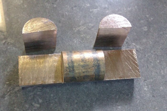
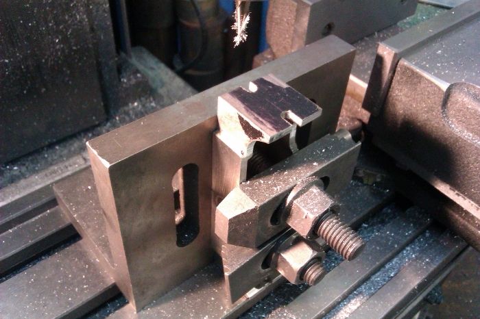
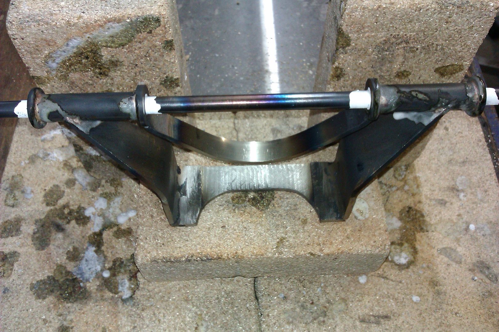
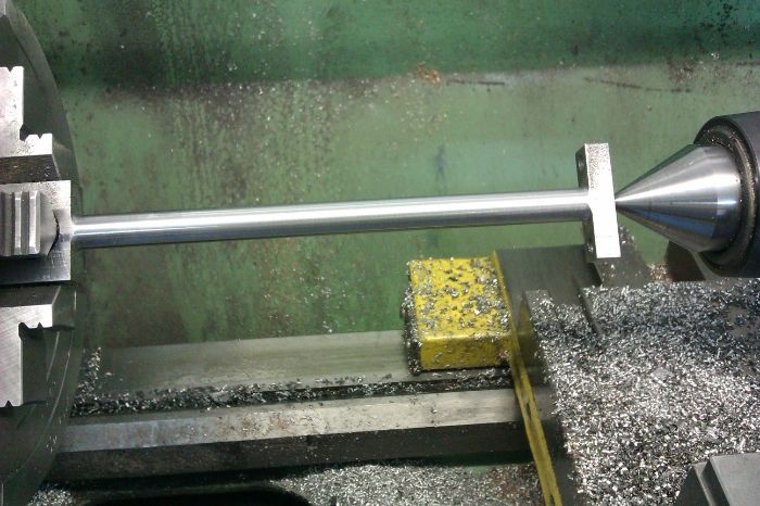
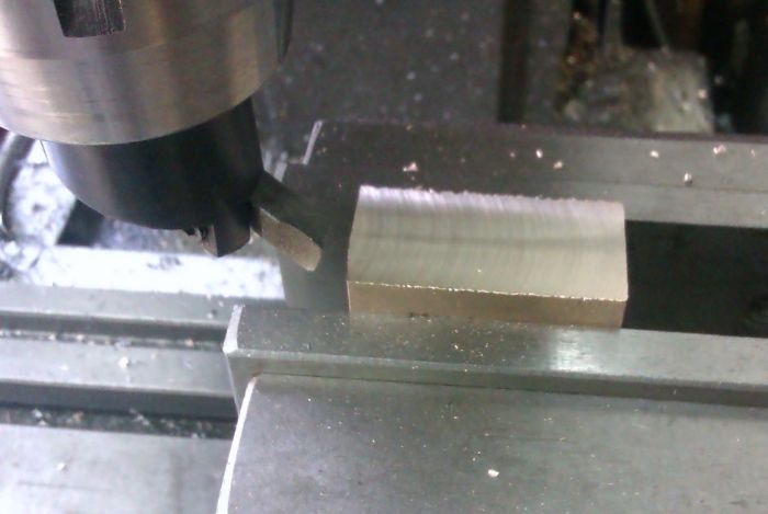
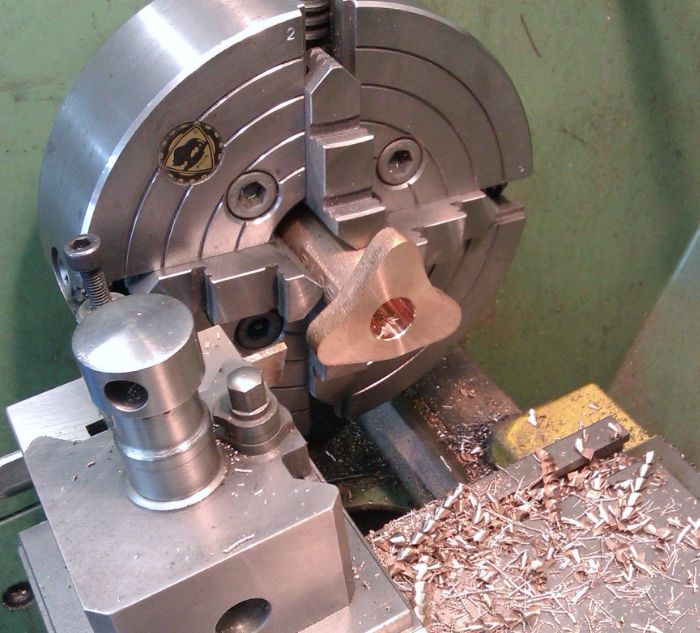
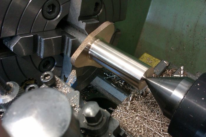
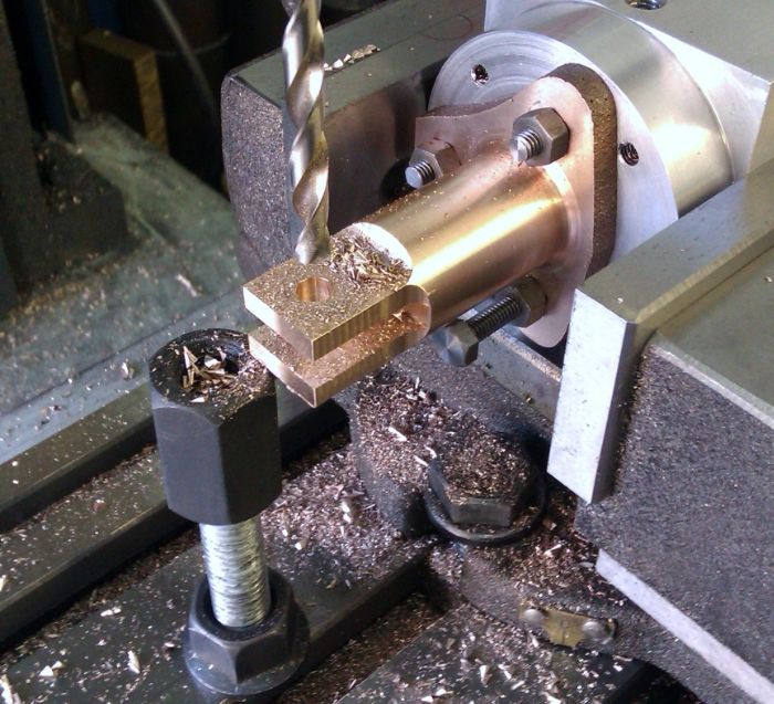
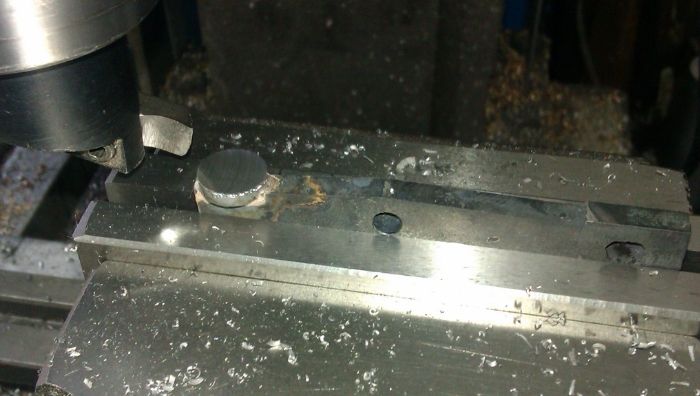
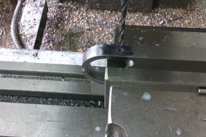
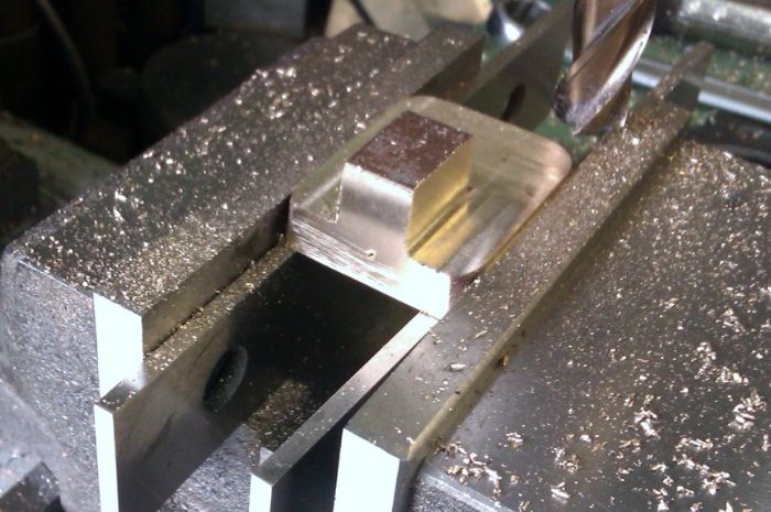
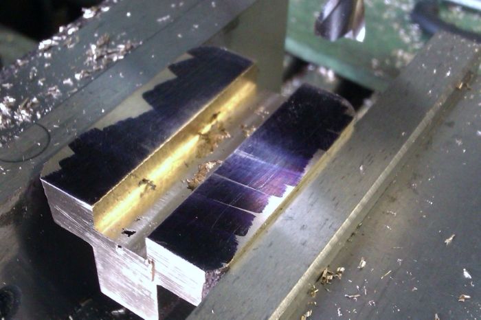
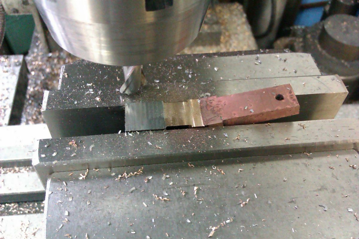
The faces were milled flat and then soft soldered together before transfering to the lathe to machine to shape
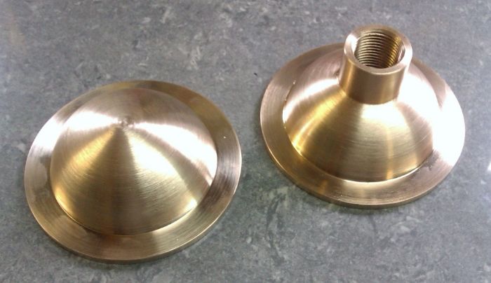
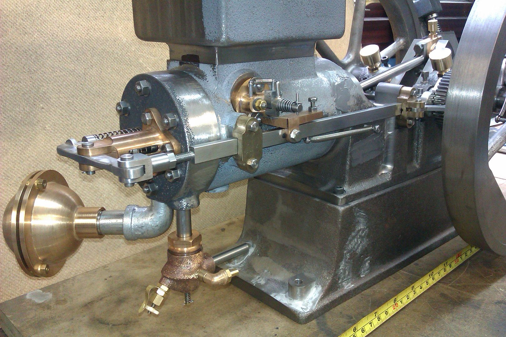
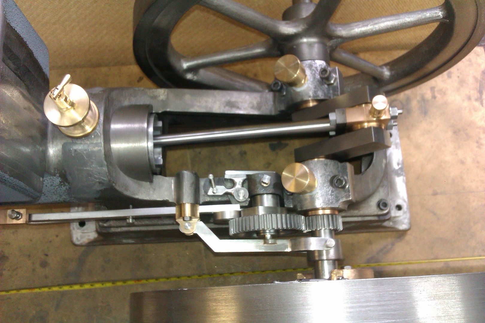
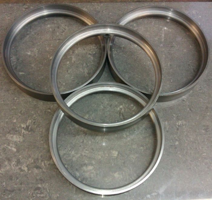
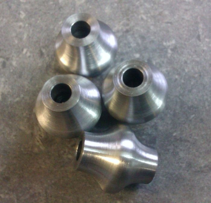
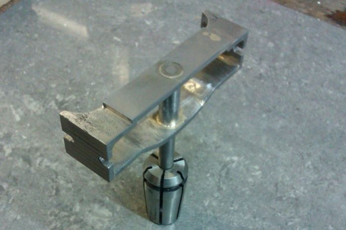
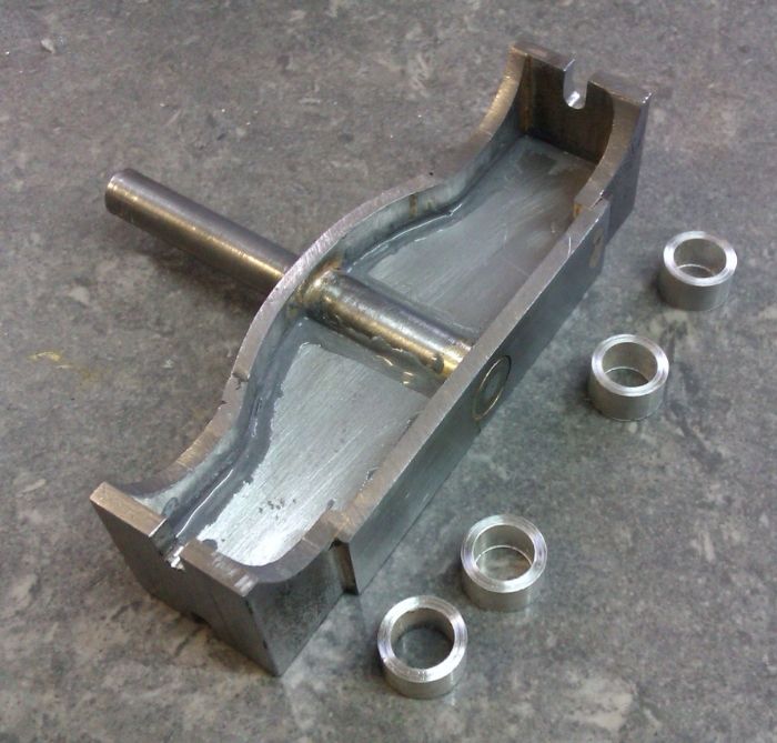
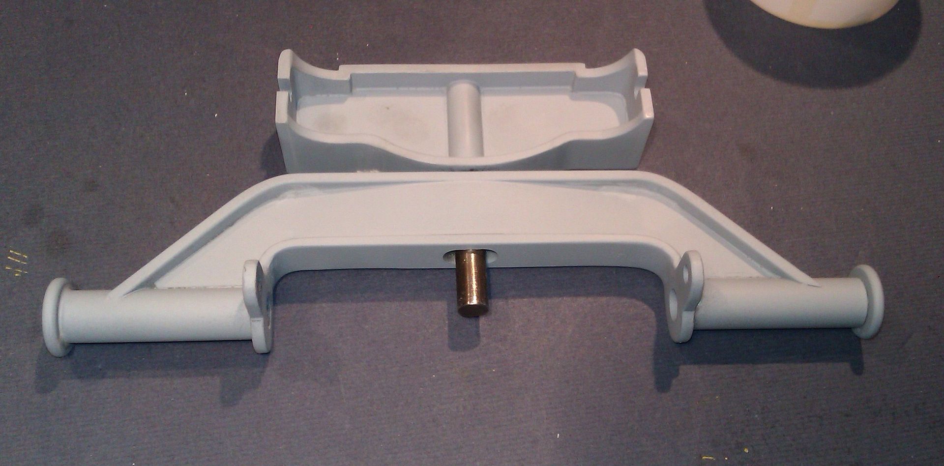
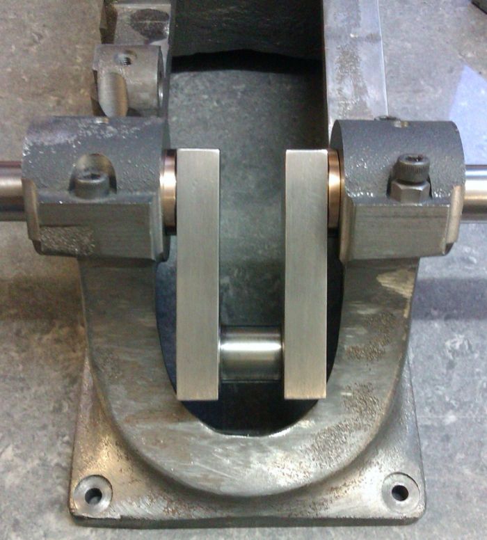
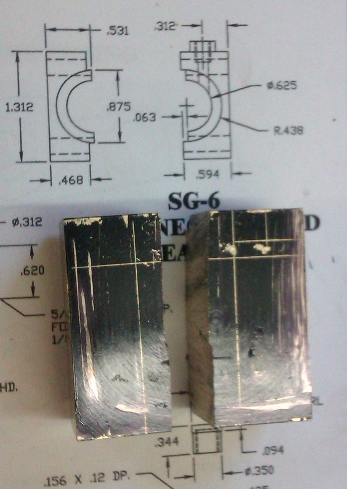
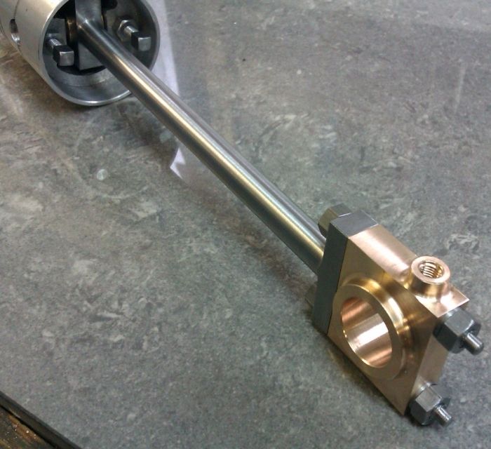
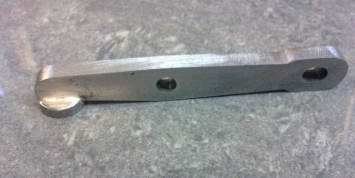
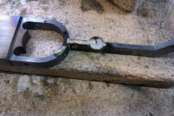
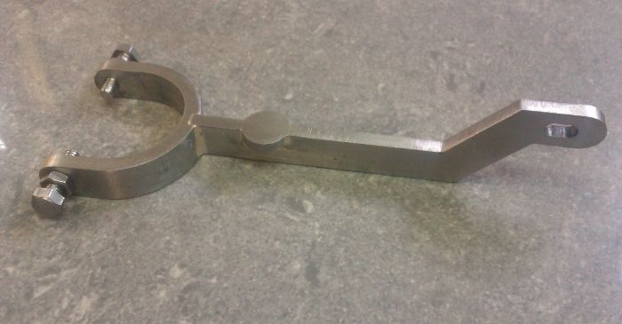
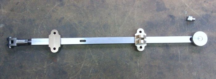
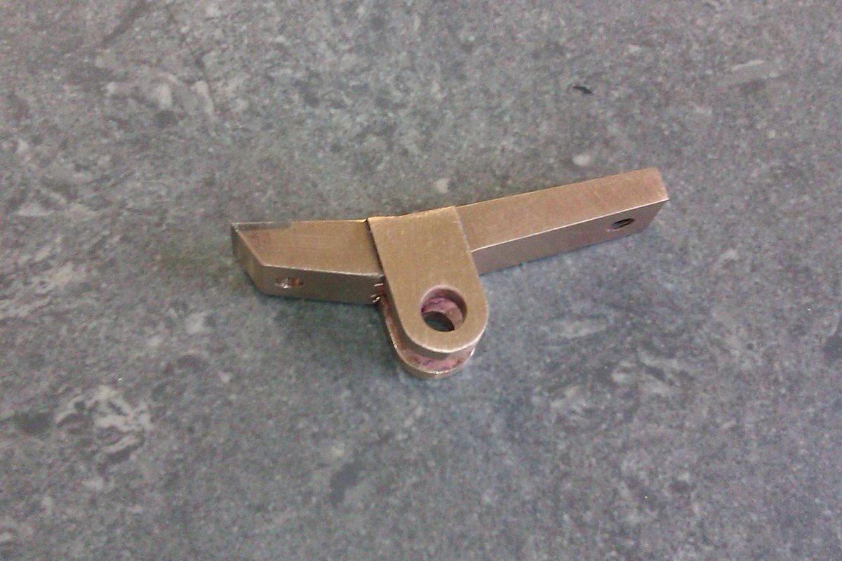
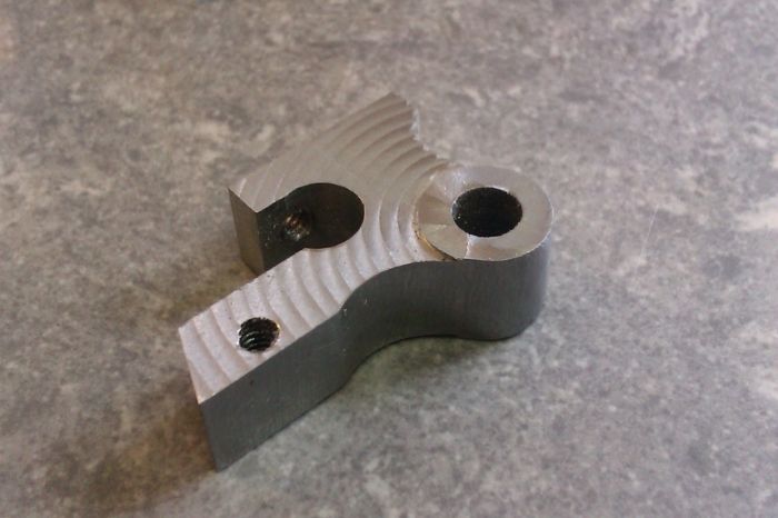
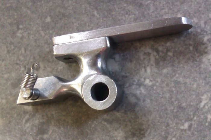
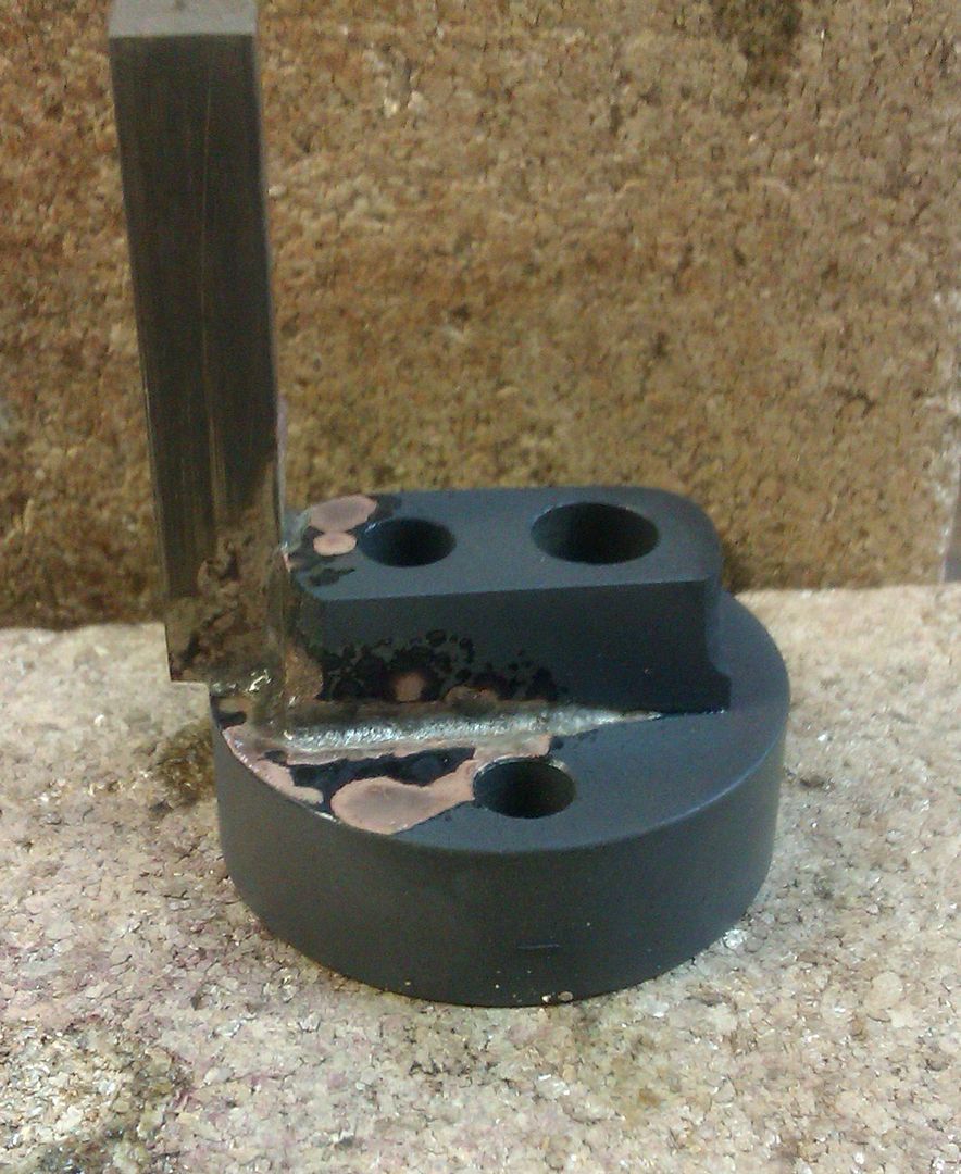
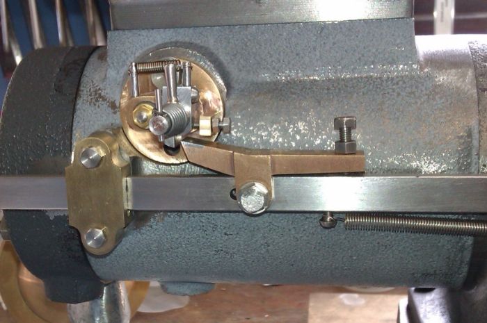
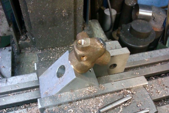
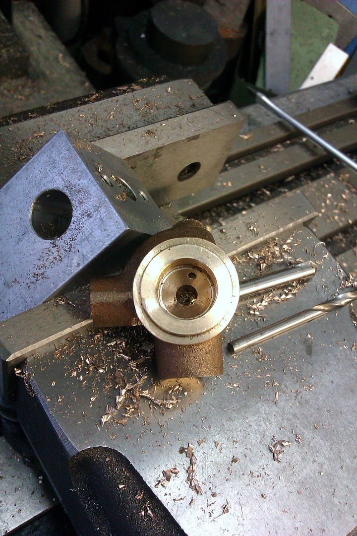
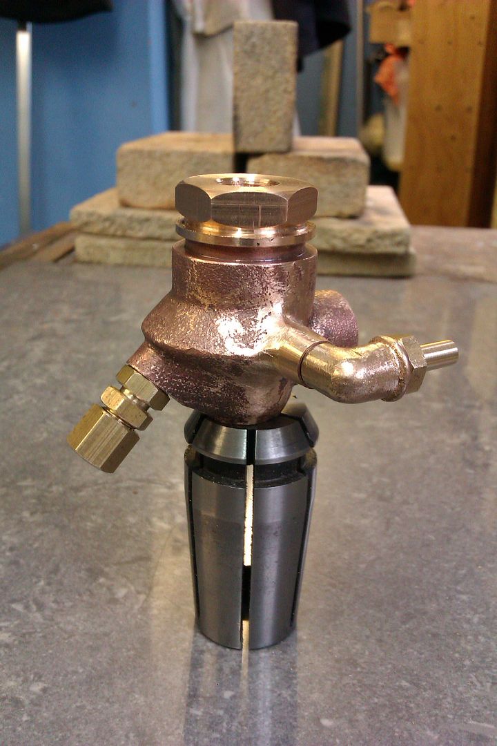
The finished bearings sitting in place
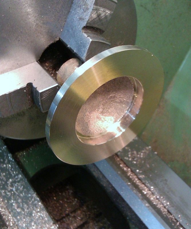
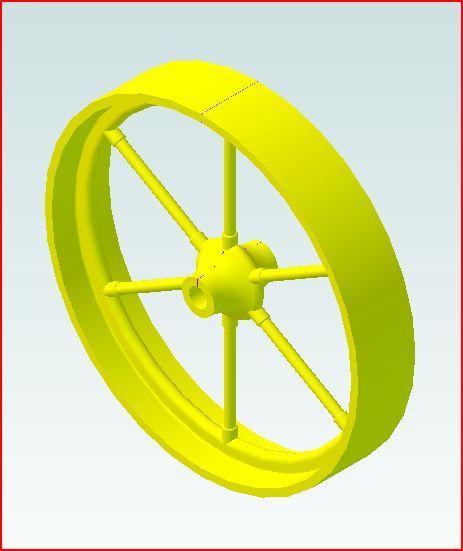
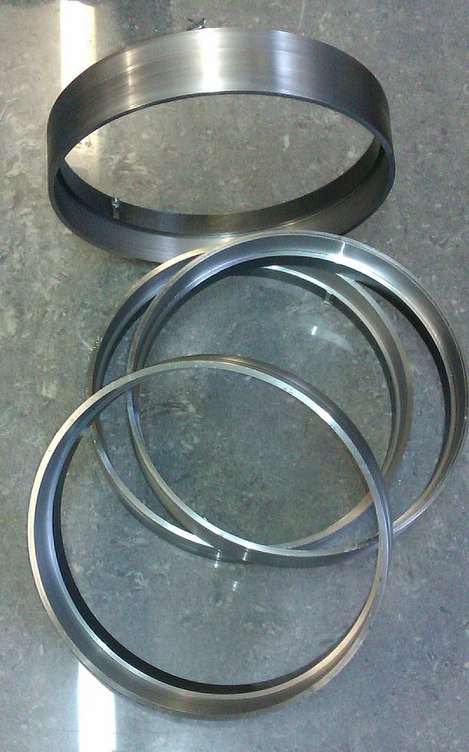
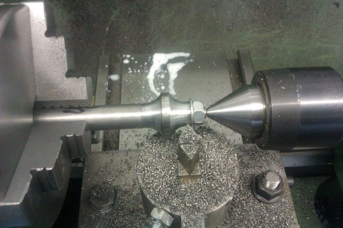
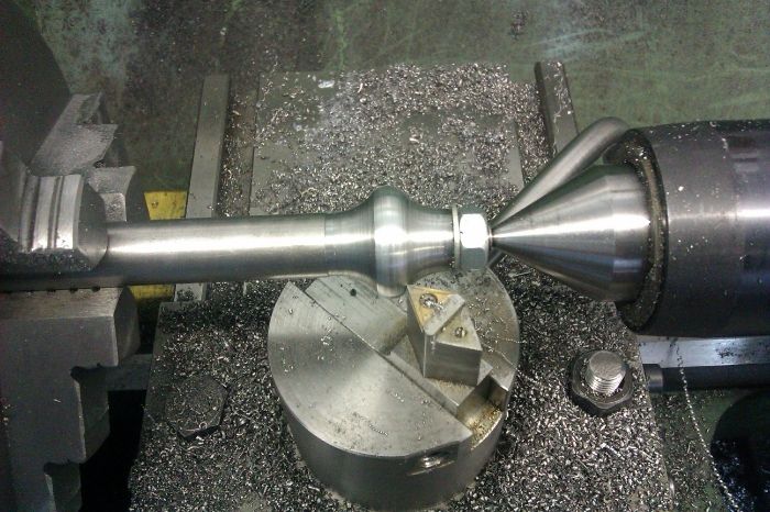
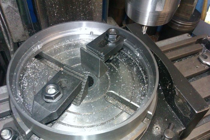
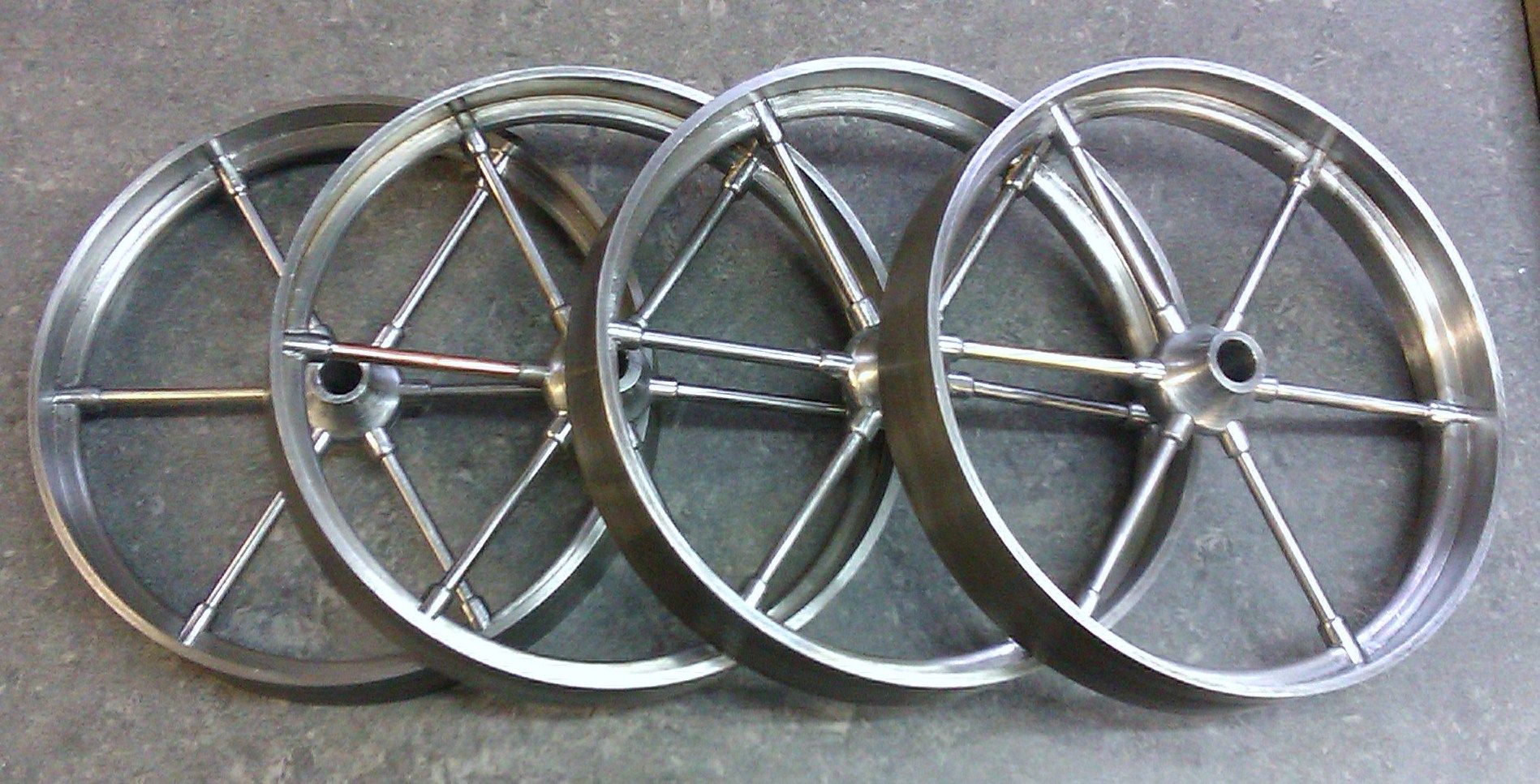
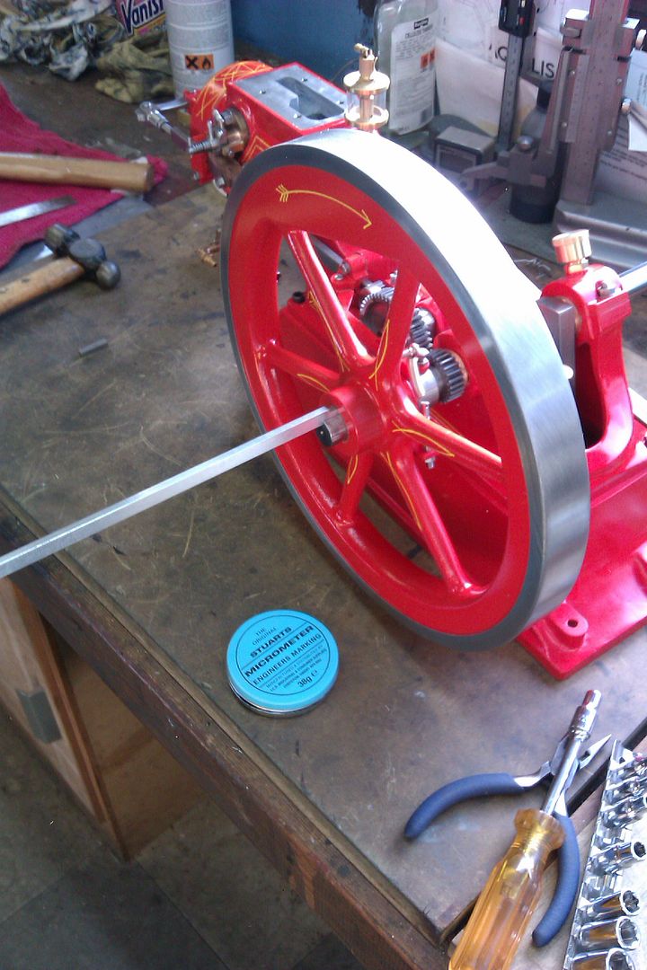
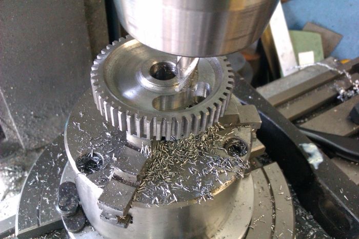
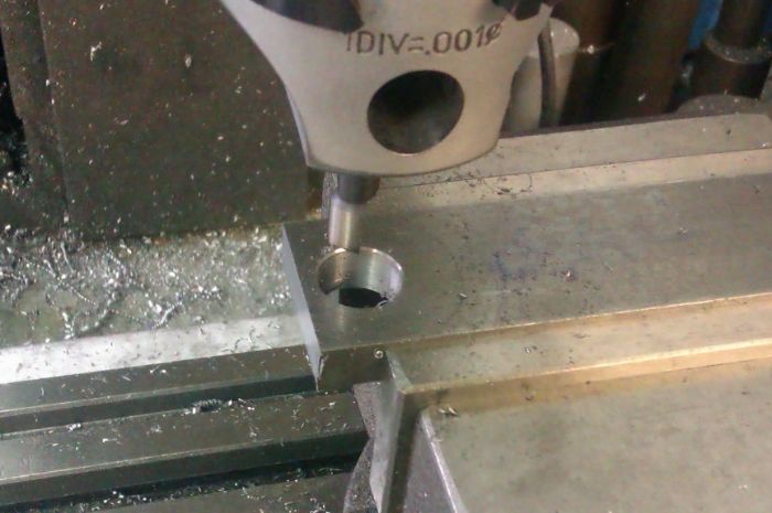
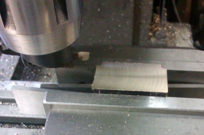
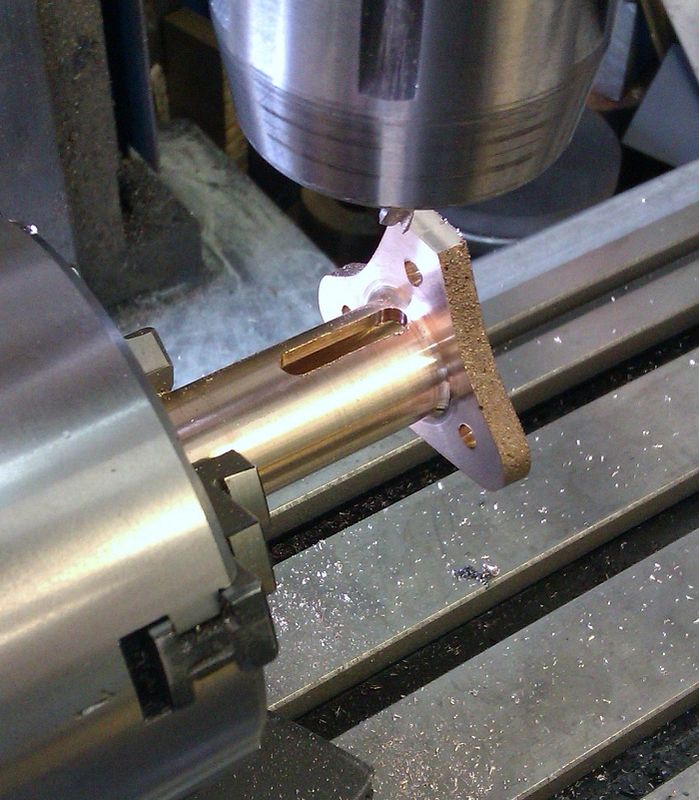
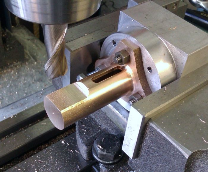
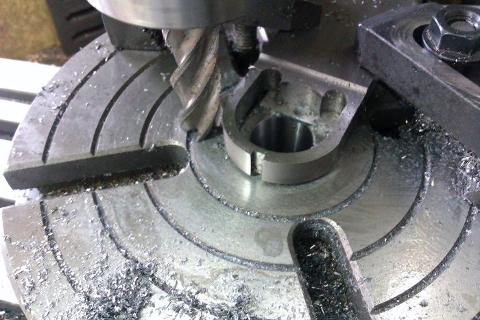
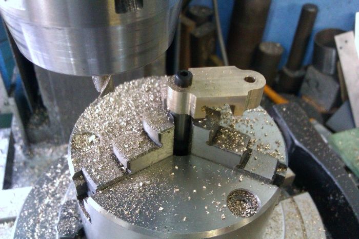
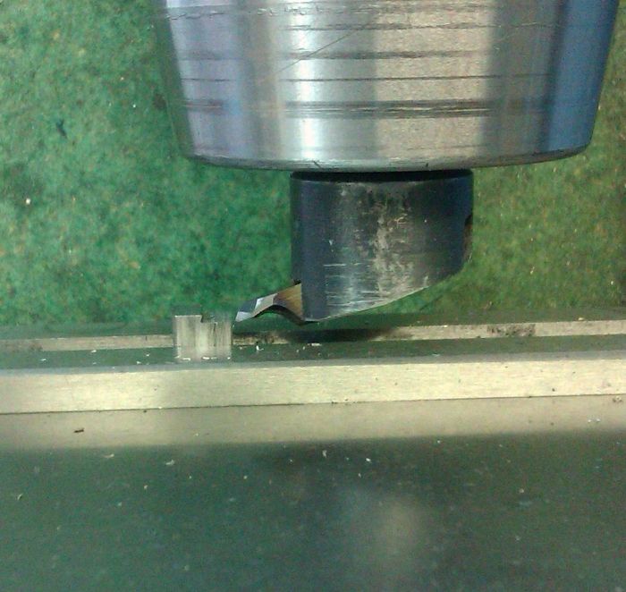
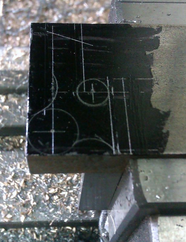
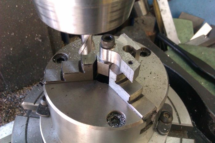
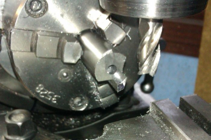
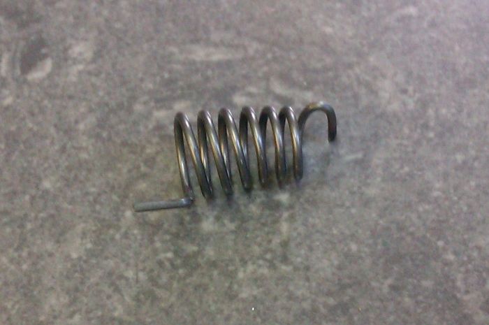
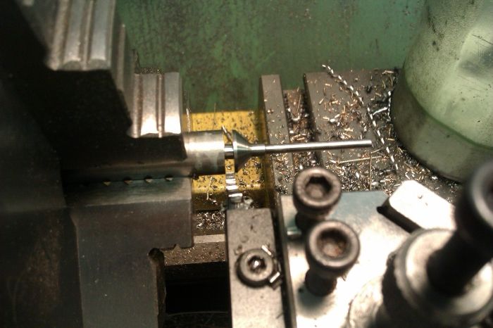
Looking for a quick job one evening I decided to make the supplied timing gear a bit more like the ones on the full size engine as the supplied one is just a plain gear
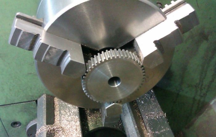
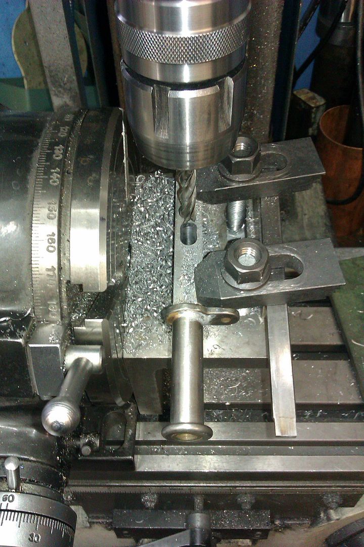
I dished out the face and then used the rotary table to cut the window in the central web
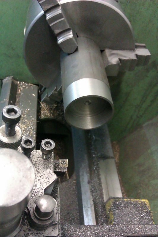
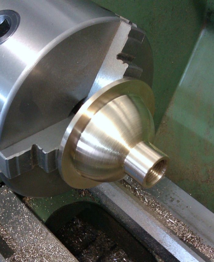
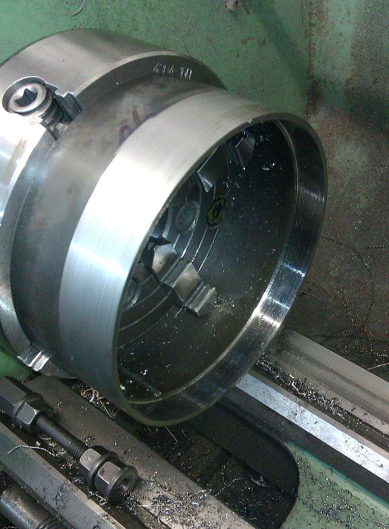
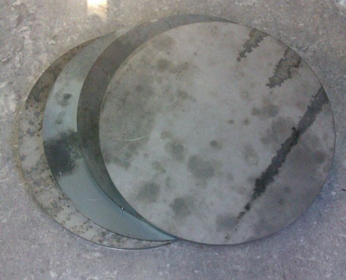
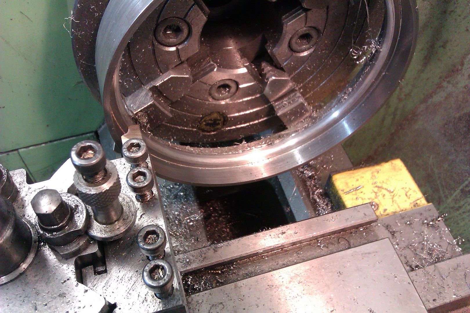
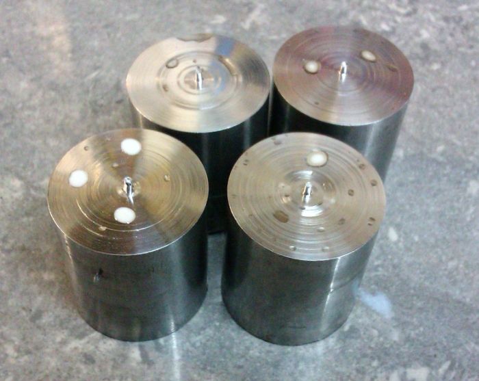
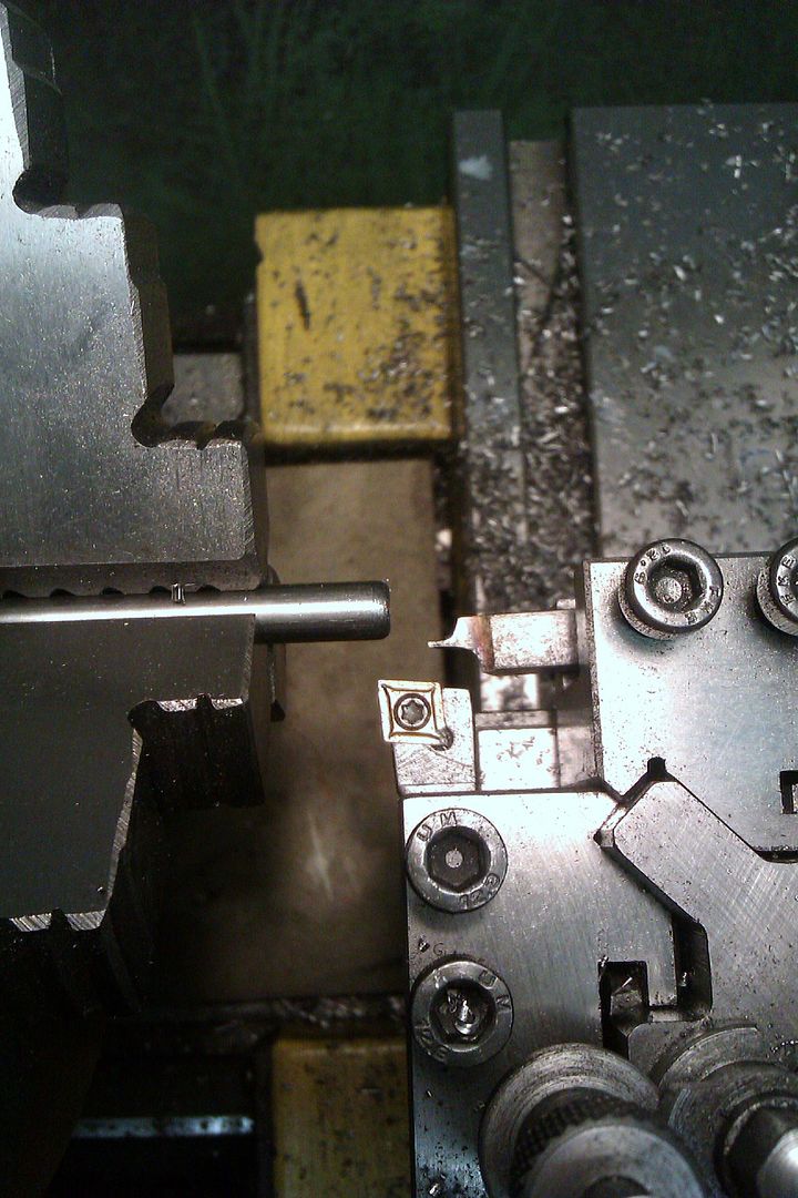
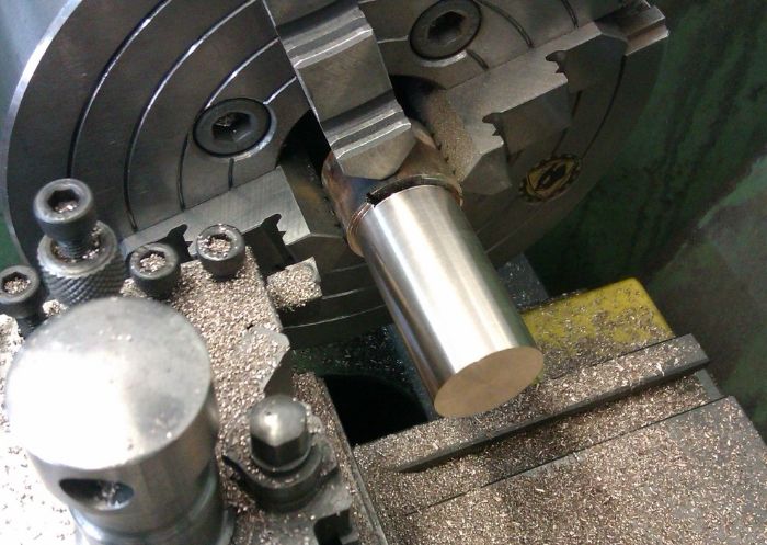
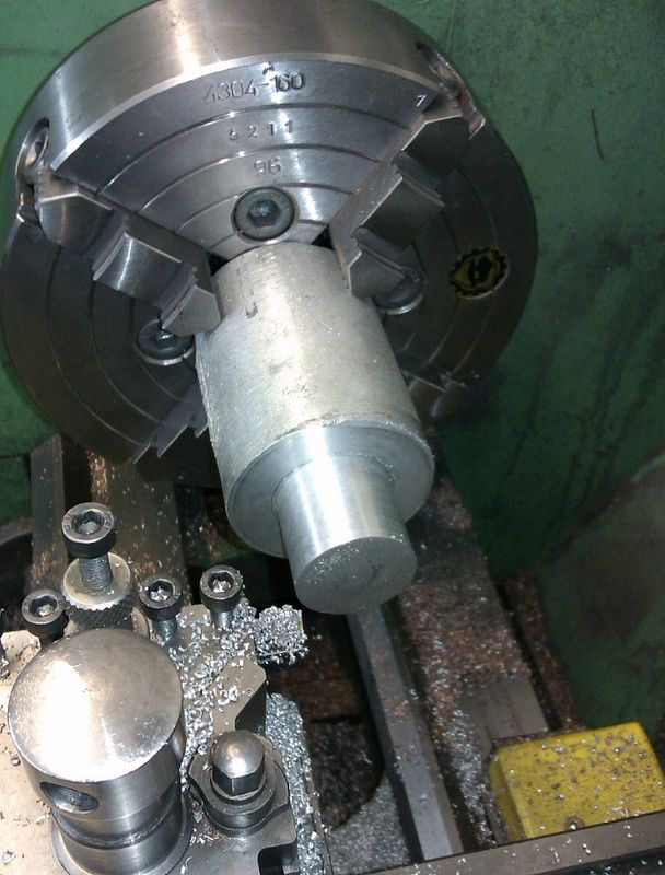
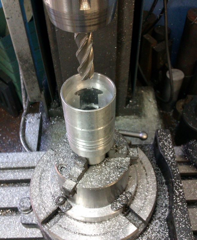
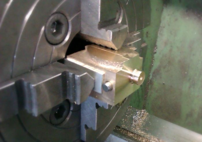
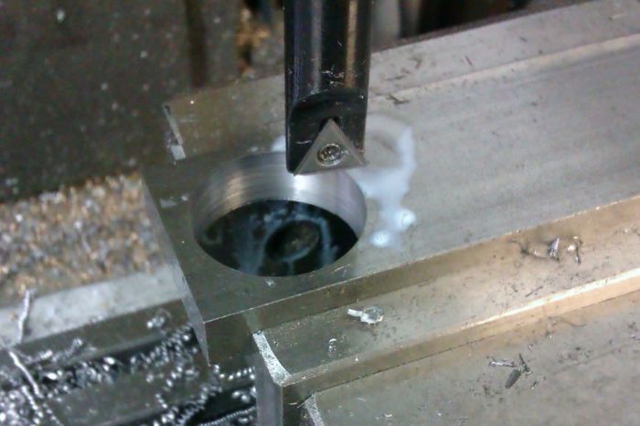
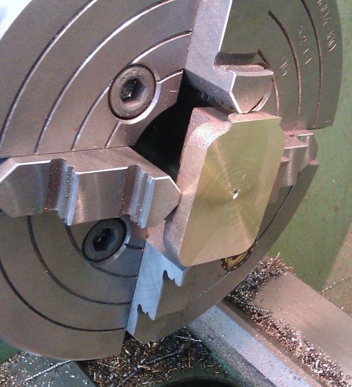
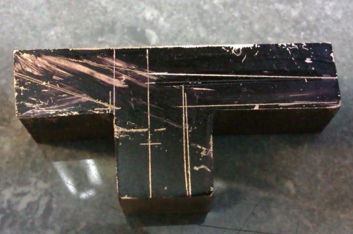
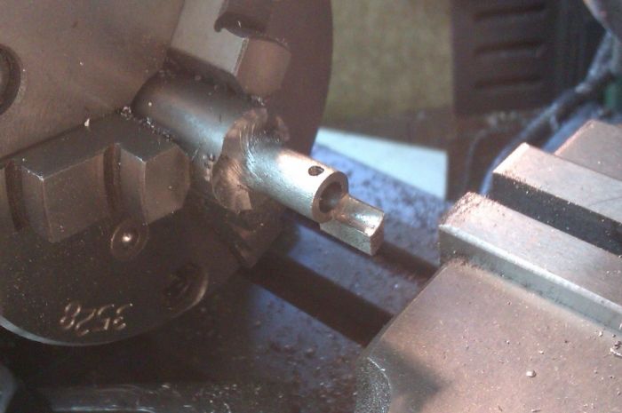
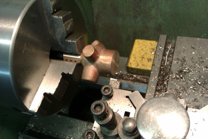
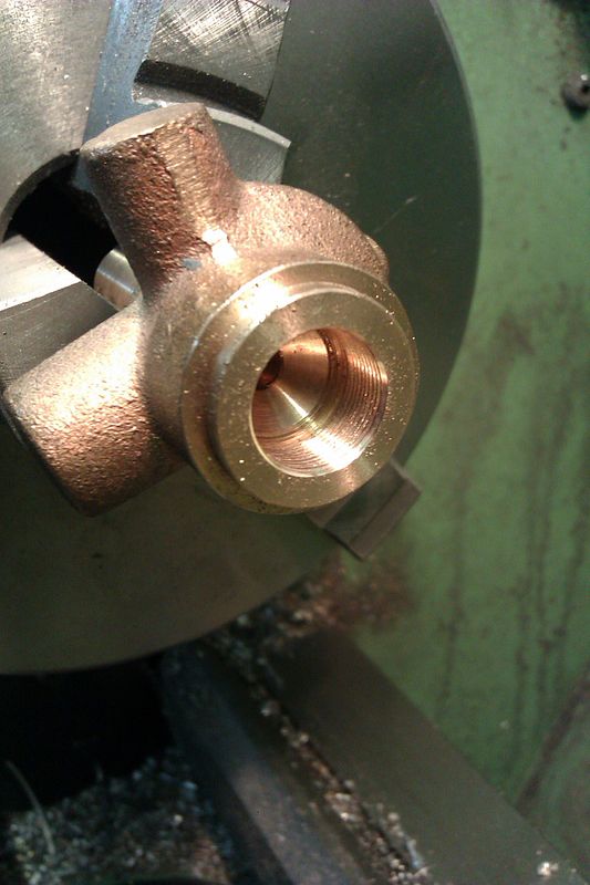
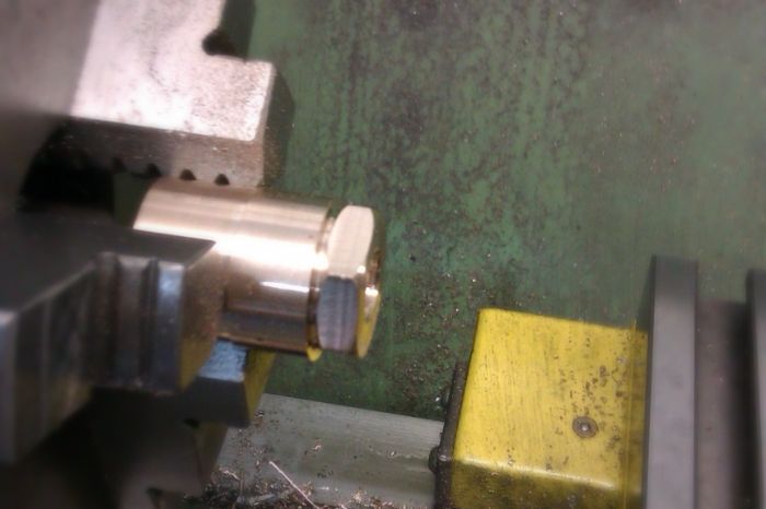
The piston is supplied as an aluminium casting with a large chucking spigot on one end, this was trued up first to get a decent surface to hold onto.
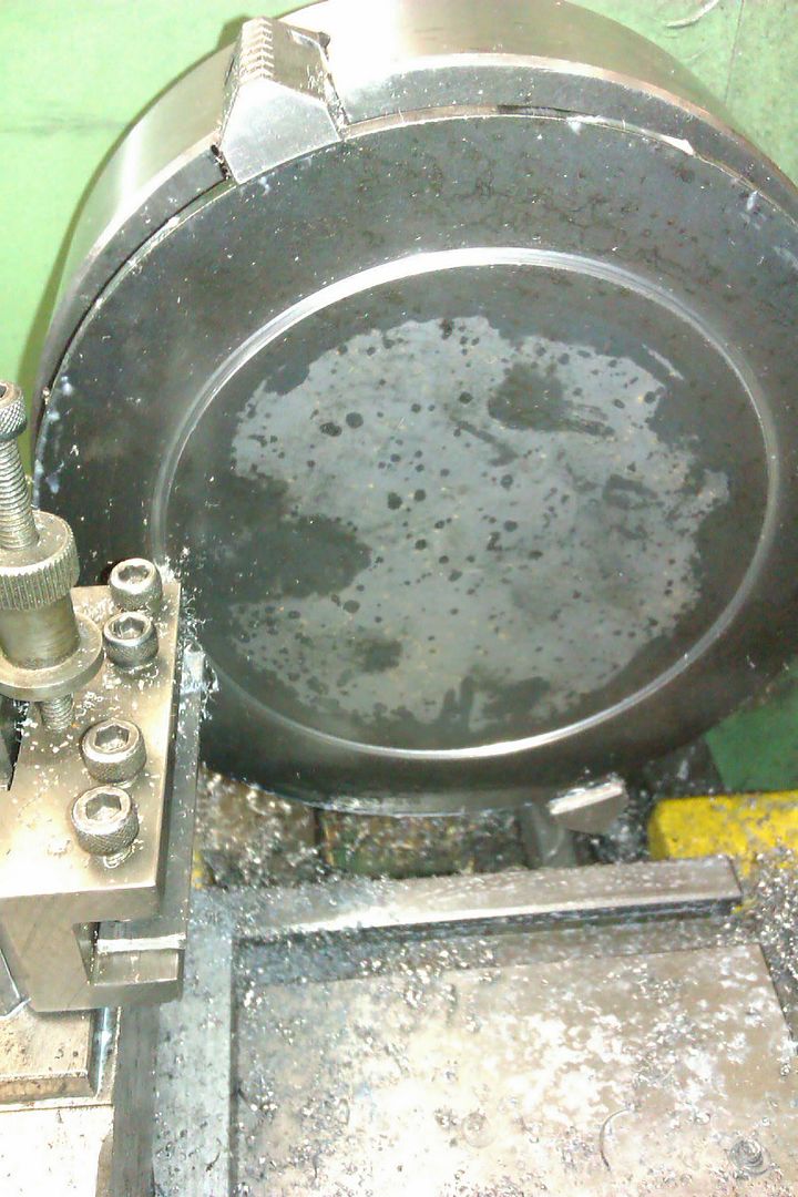
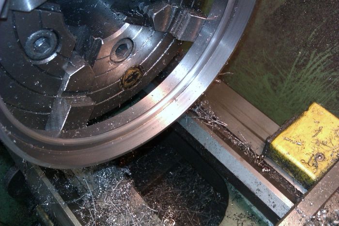
I clocked the inner cast surfaces true and then took a cut off the end and took the OD down to 0.050" oversize.
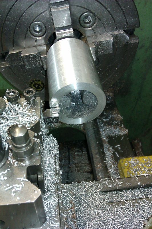
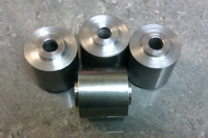
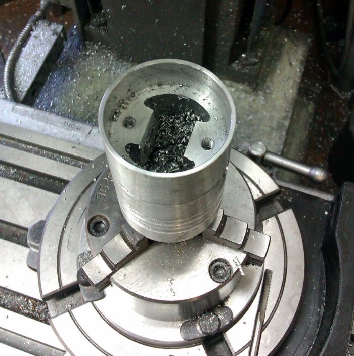
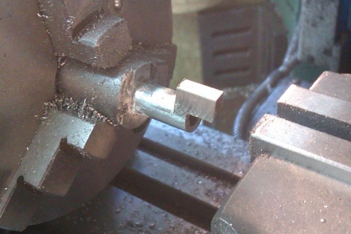
And then used a boring bar to hollow out the skirt to size before leaving the casting to cool.
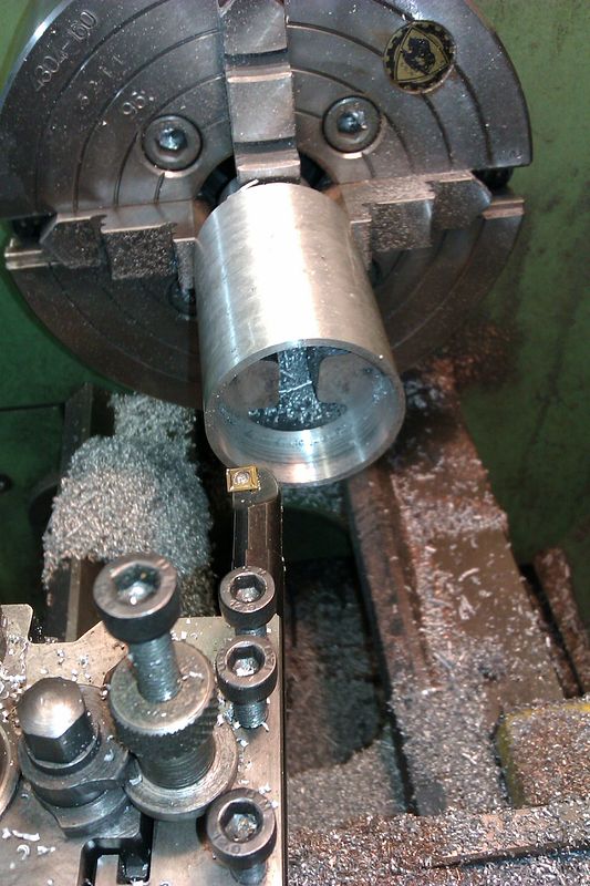
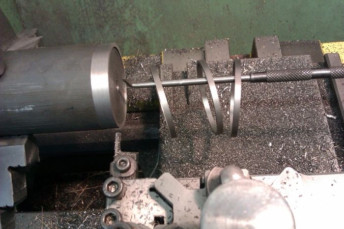
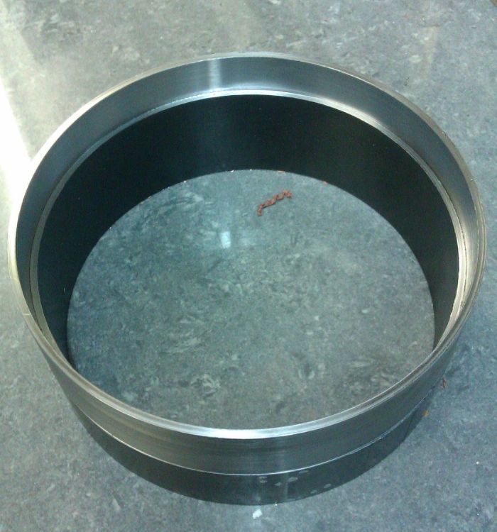
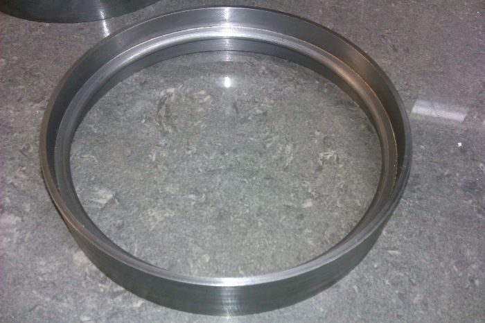
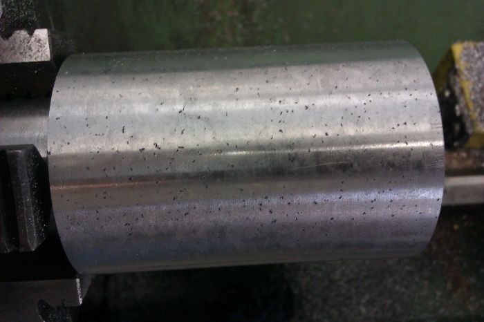
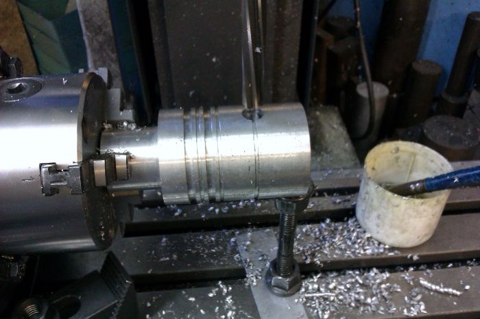
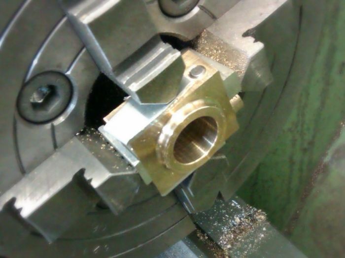
I then went back and machined the OD to size at which point the casting started to look a bit porus but it should be OK in use.
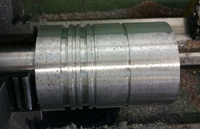
So I carried on and cut the ring and oil grooves
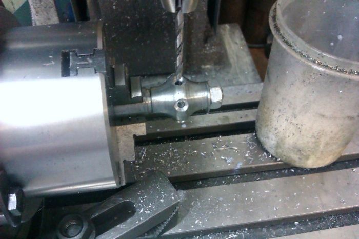
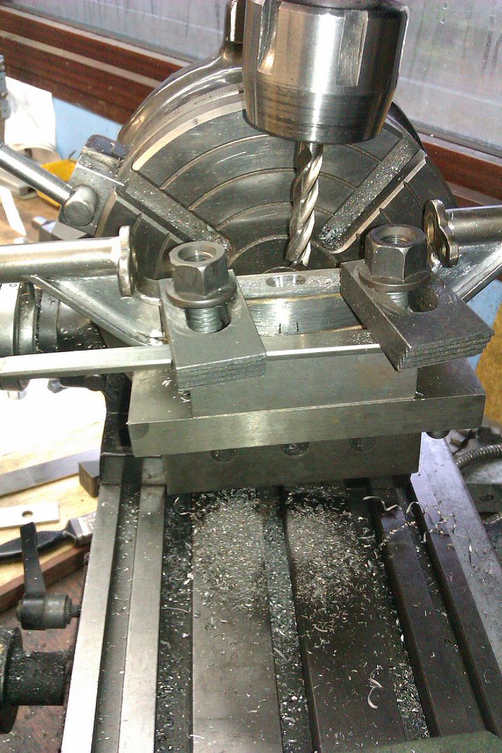
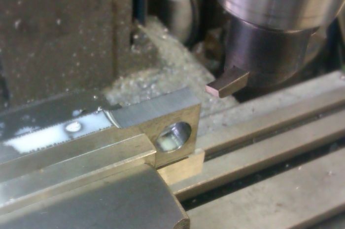
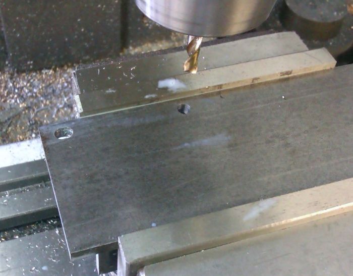
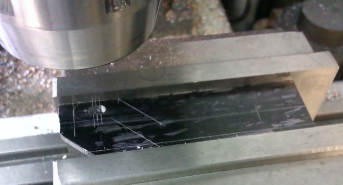
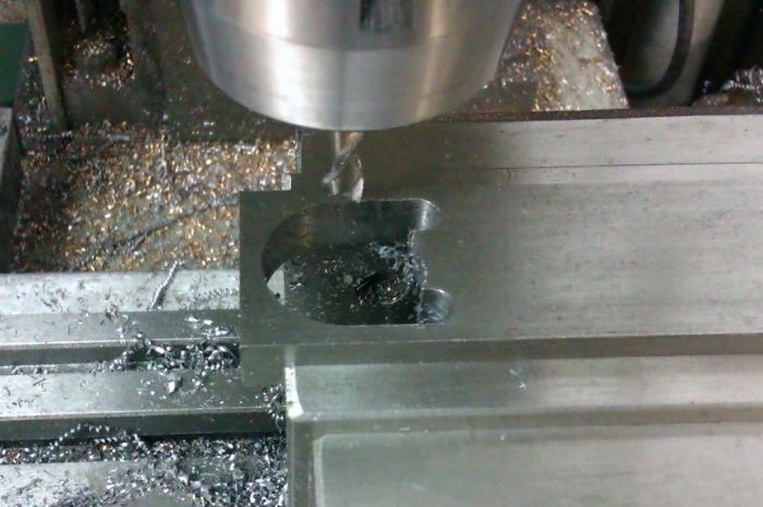
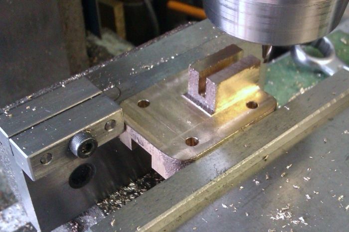
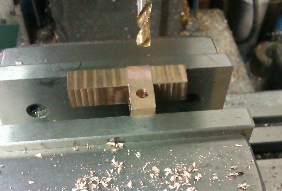
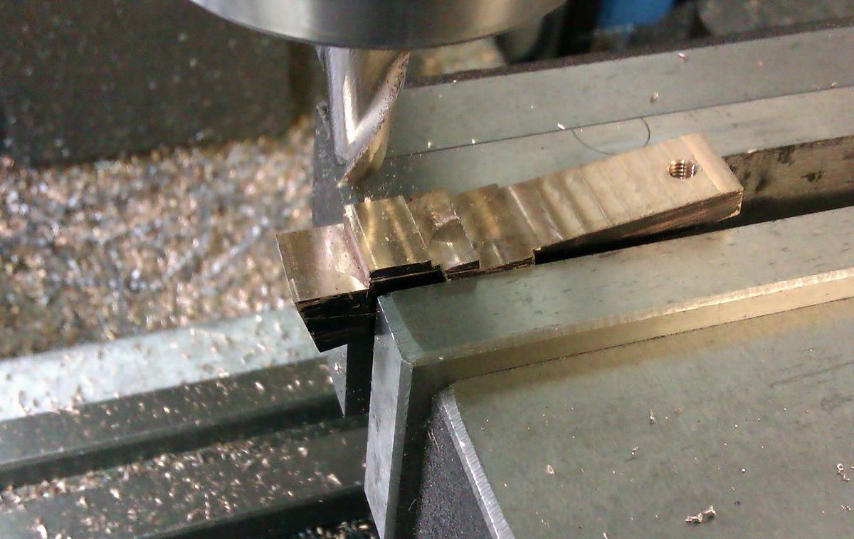
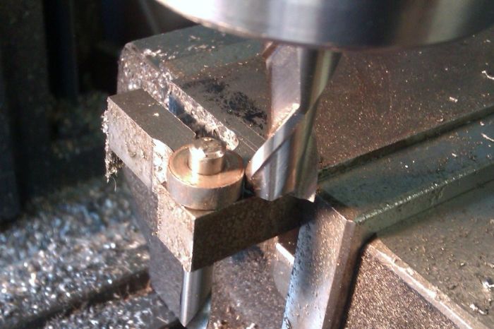
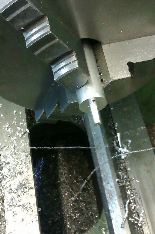
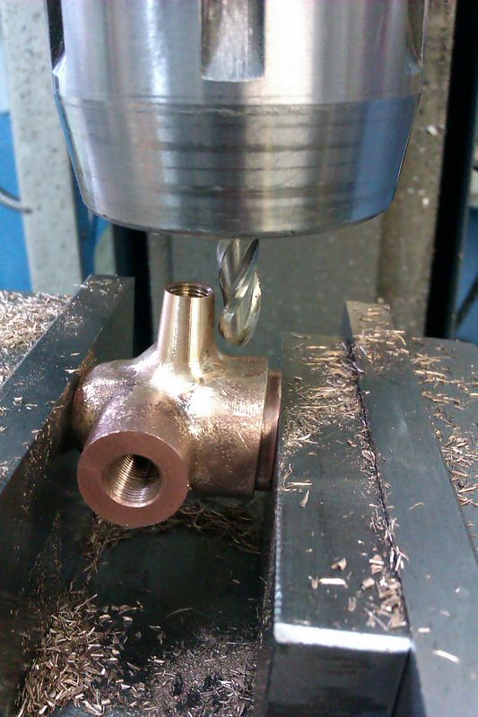
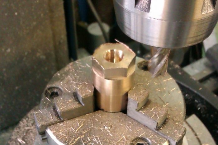
Over to the mill to take the gap for the conrod to width
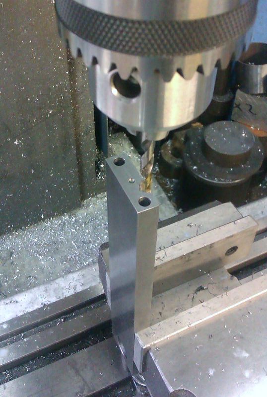
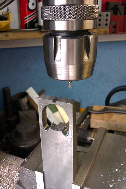
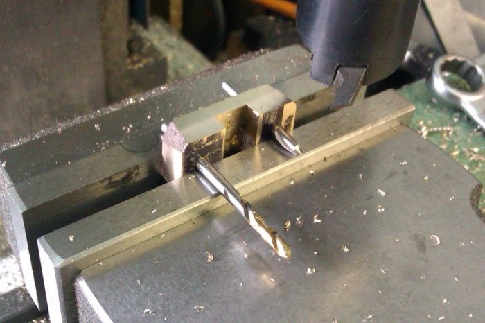
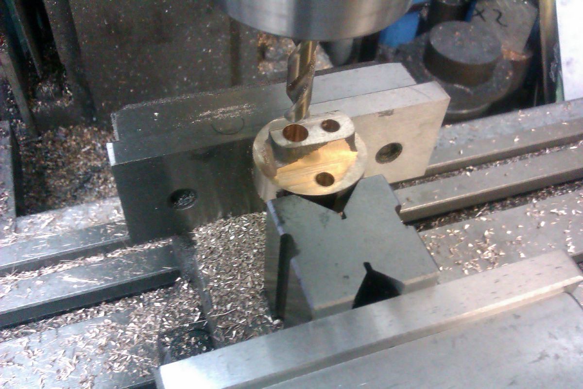
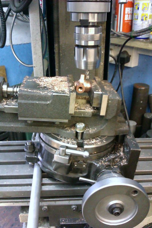
Then without rotating the table mounted it vertically so the pin hole is at right angles to the previously machined faces
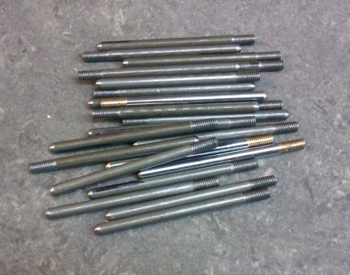
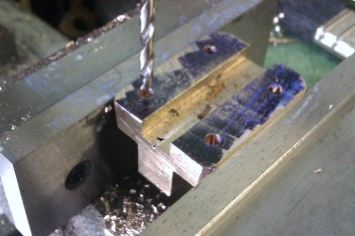
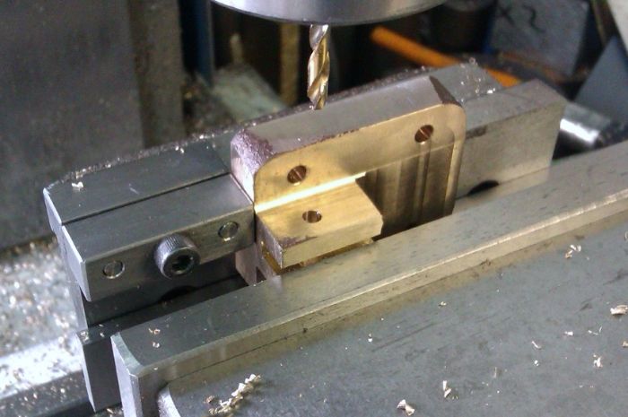
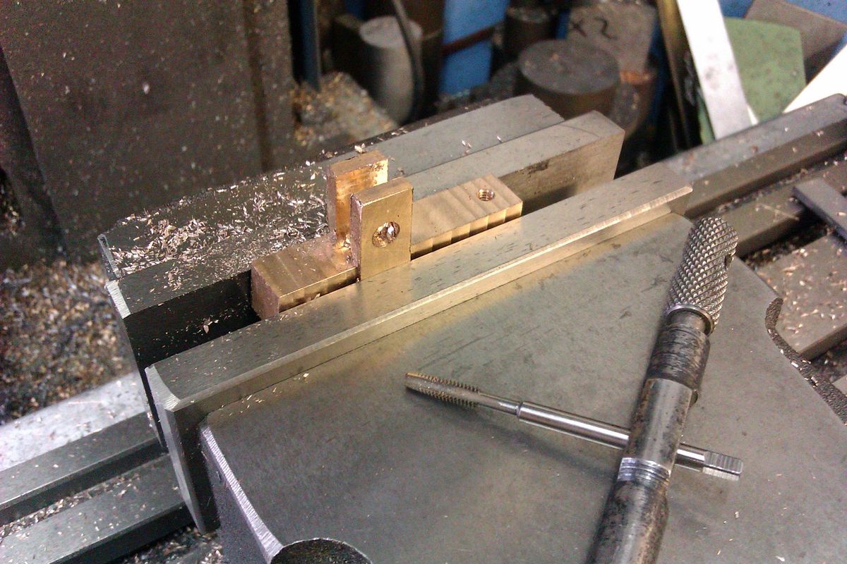
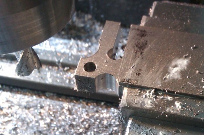
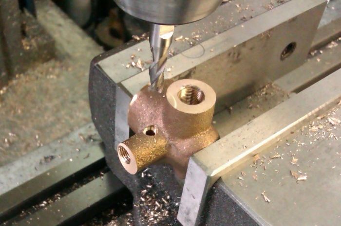
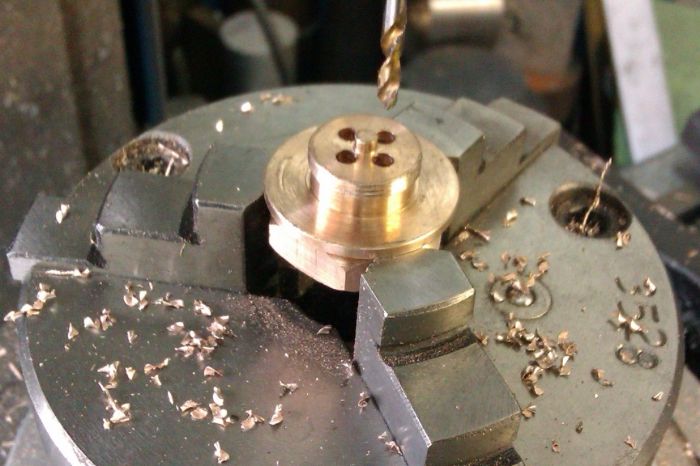
Then drill and thread the holes for the pin retaining screws.
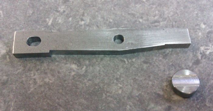
It was then machined to length to complete.
J
The faces were milled flat and then soft soldered together before transfering to the lathe to machine to shape
The finished bearings sitting in place
Looking for a quick job one evening I decided to make the supplied timing gear a bit more like the ones on the full size engine as the supplied one is just a plain gear
I dished out the face and then used the rotary table to cut the window in the central web
The piston is supplied as an aluminium casting with a large chucking spigot on one end, this was trued up first to get a decent surface to hold onto.
I clocked the inner cast surfaces true and then took a cut off the end and took the OD down to 0.050" oversize.
And then used a boring bar to hollow out the skirt to size before leaving the casting to cool.
I then went back and machined the OD to size at which point the casting started to look a bit porus but it should be OK in use.
So I carried on and cut the ring and oil grooves
Over to the mill to take the gap for the conrod to width
Then without rotating the table mounted it vertically so the pin hole is at right angles to the previously machined faces
Then drill and thread the holes for the pin retaining screws.
It was then machined to length to complete.
J

![DreamPlan Home Design and Landscaping Software Free for Windows [PC Download]](https://m.media-amazon.com/images/I/51kvZH2dVLL._SL500_.jpg)
![MeshMagic 3D Free 3D Modeling Software [Download]](https://m.media-amazon.com/images/I/B1U+p8ewjGS._SL500_.png)


")