1/2 scale advance-rumley 60-20 traction engine

Home Model Engine Machinist Forum

Help Support Home Model Engine Machinist Forum:

This site may earn a commission from merchant affiliate links, including eBay, Amazon, and others.
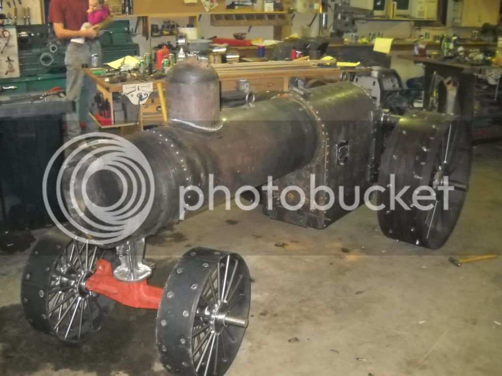
some new pics of the progress, nothing really noticable or notable, its pretty slow going at this stage.

100_0575.jpg

100_0576.jpg

100_0577.jpg

100_0578.jpg

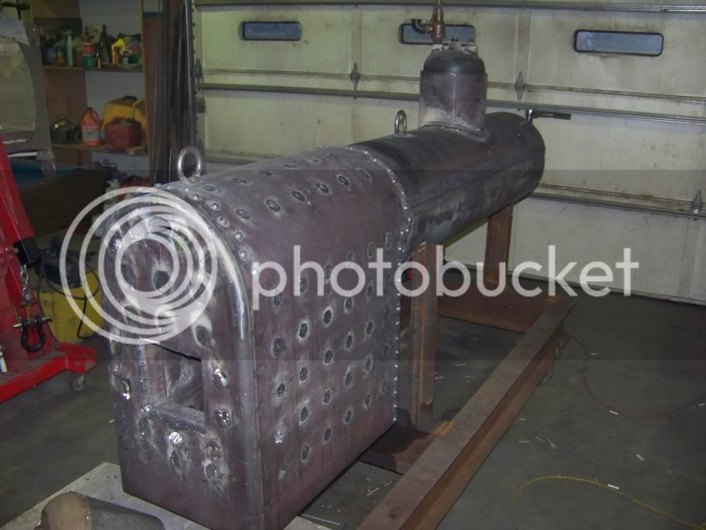
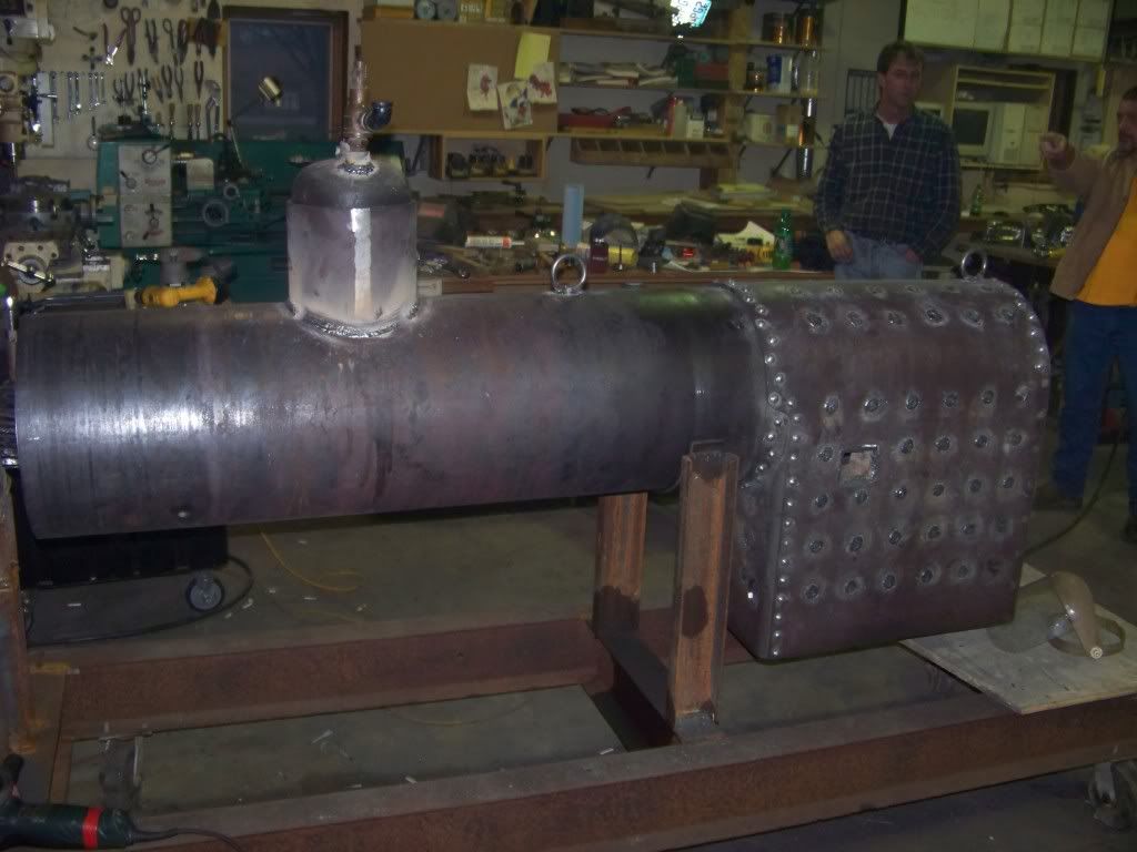
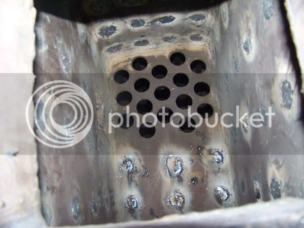
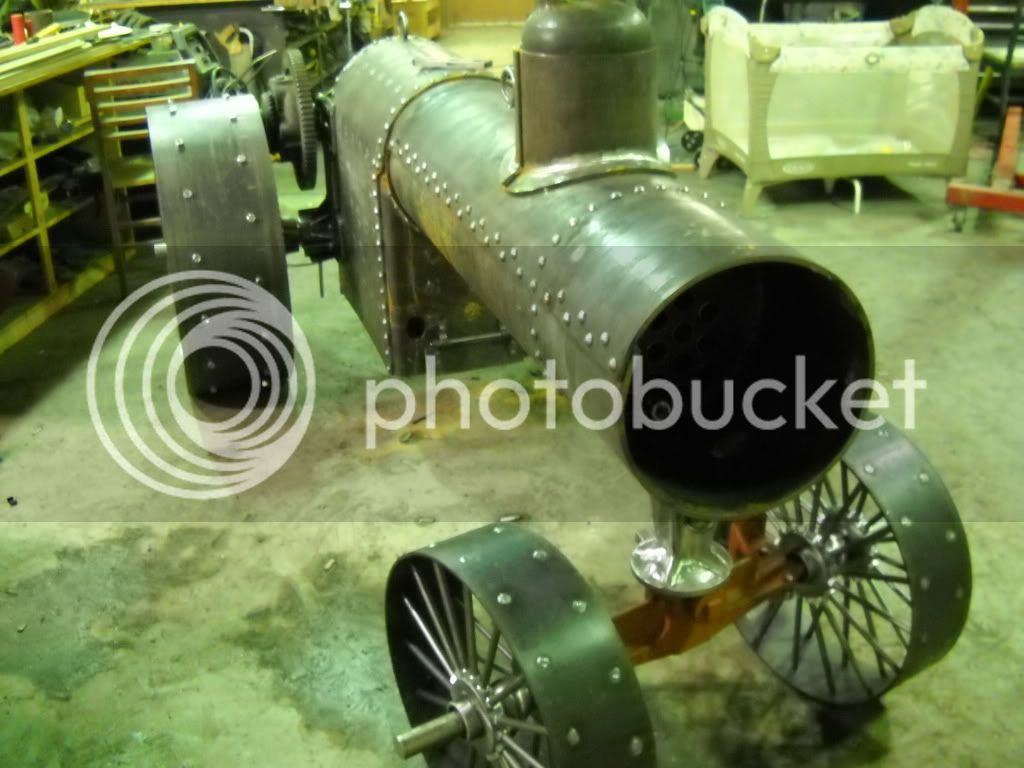
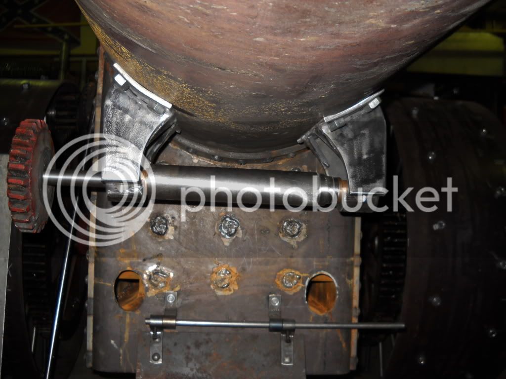
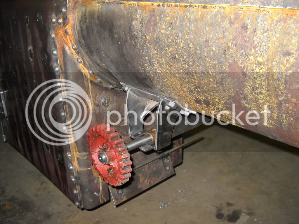
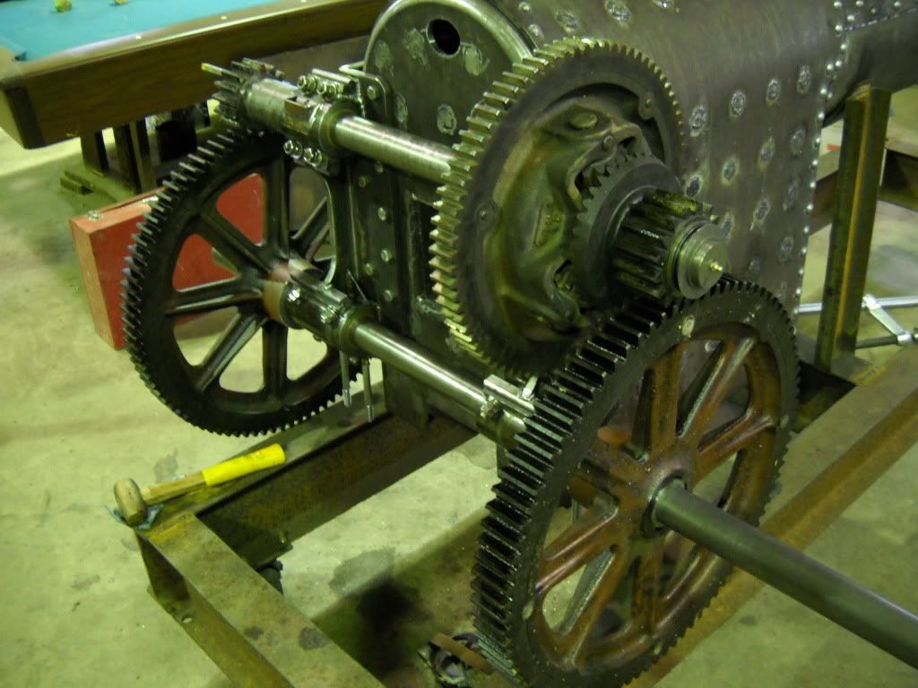
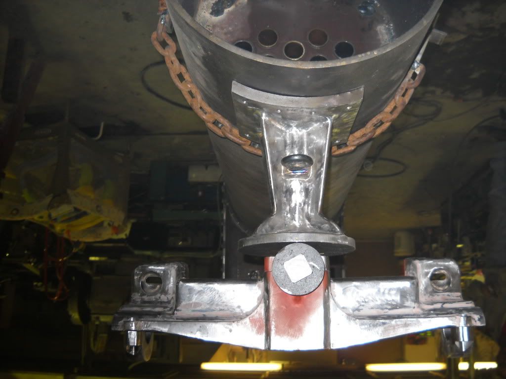
the boiler of course, there are going to be 17, 1 1/2"d x about 42" fire tubes, i think the fake rivits are going to look good.
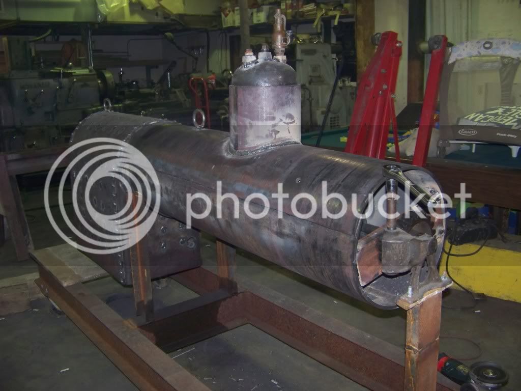
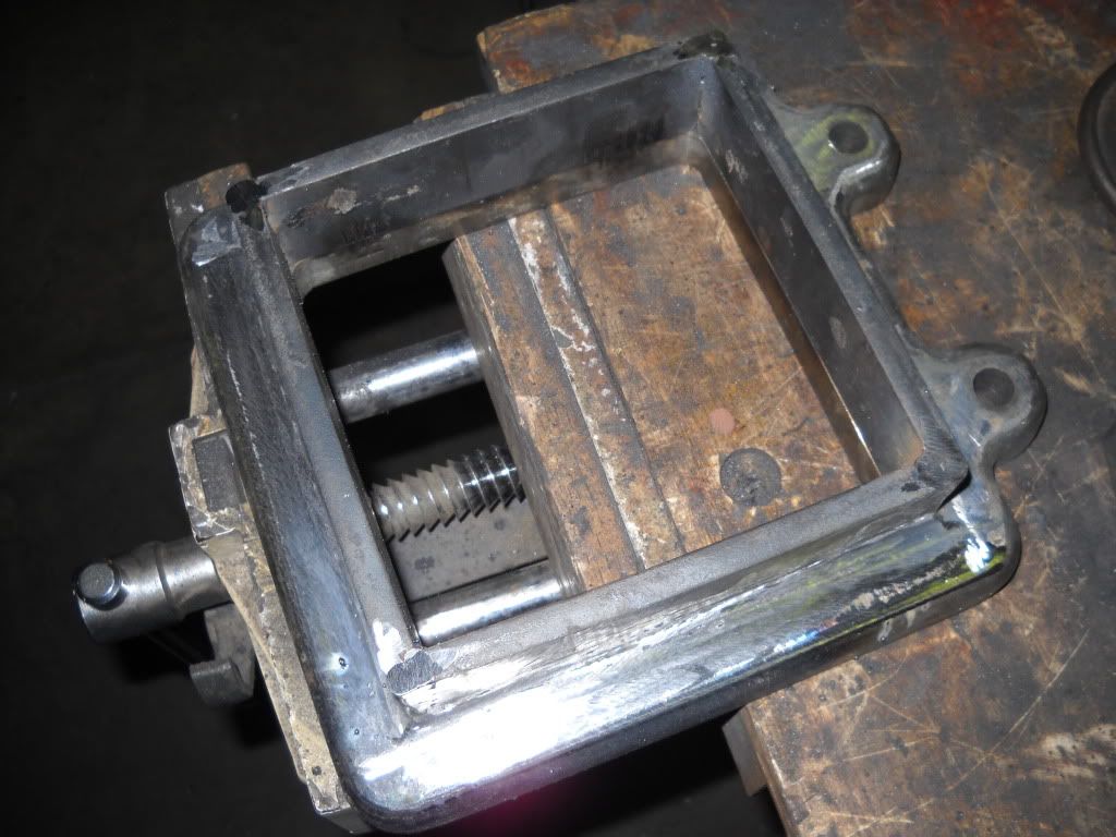
notice the way he has it riged up with the saddle and the worm gear on the front so he can rotate it easily, its alot safer and easier than doing it by hand for sure

100_0580.jpg


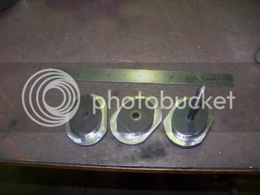
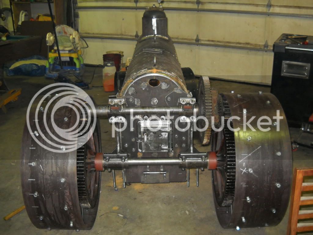
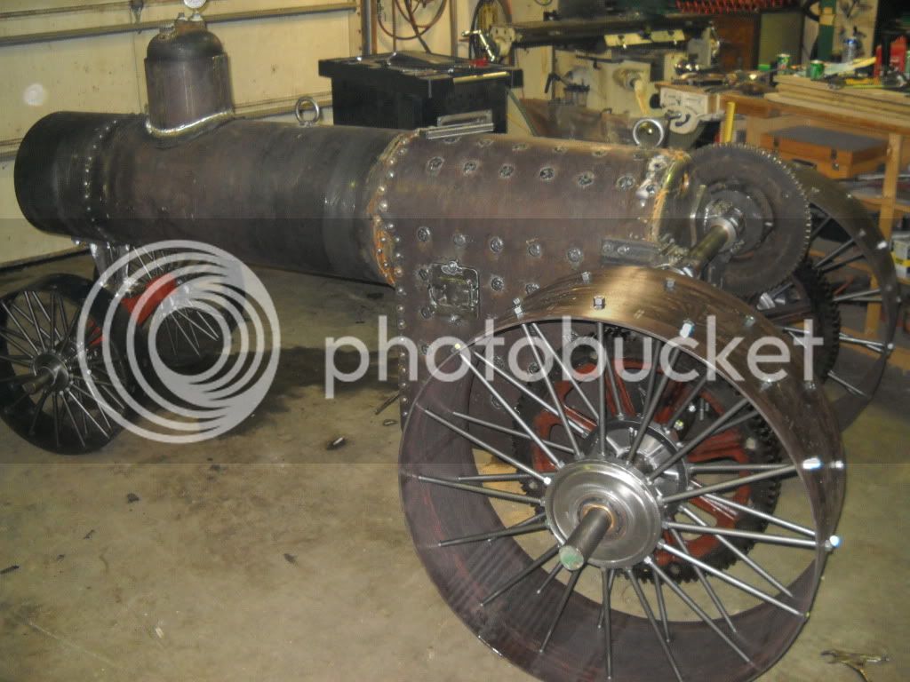
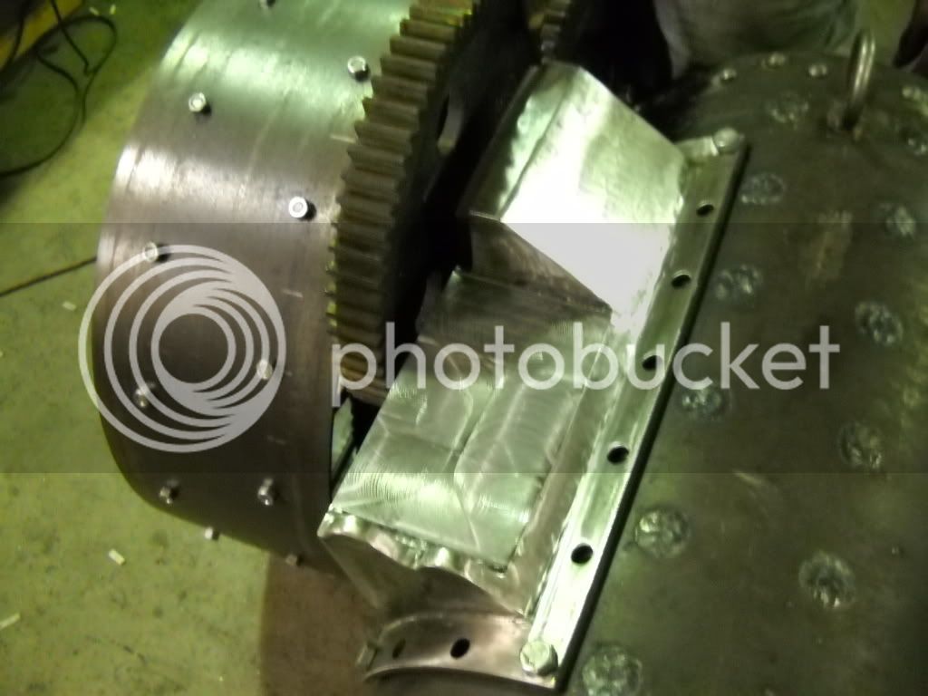
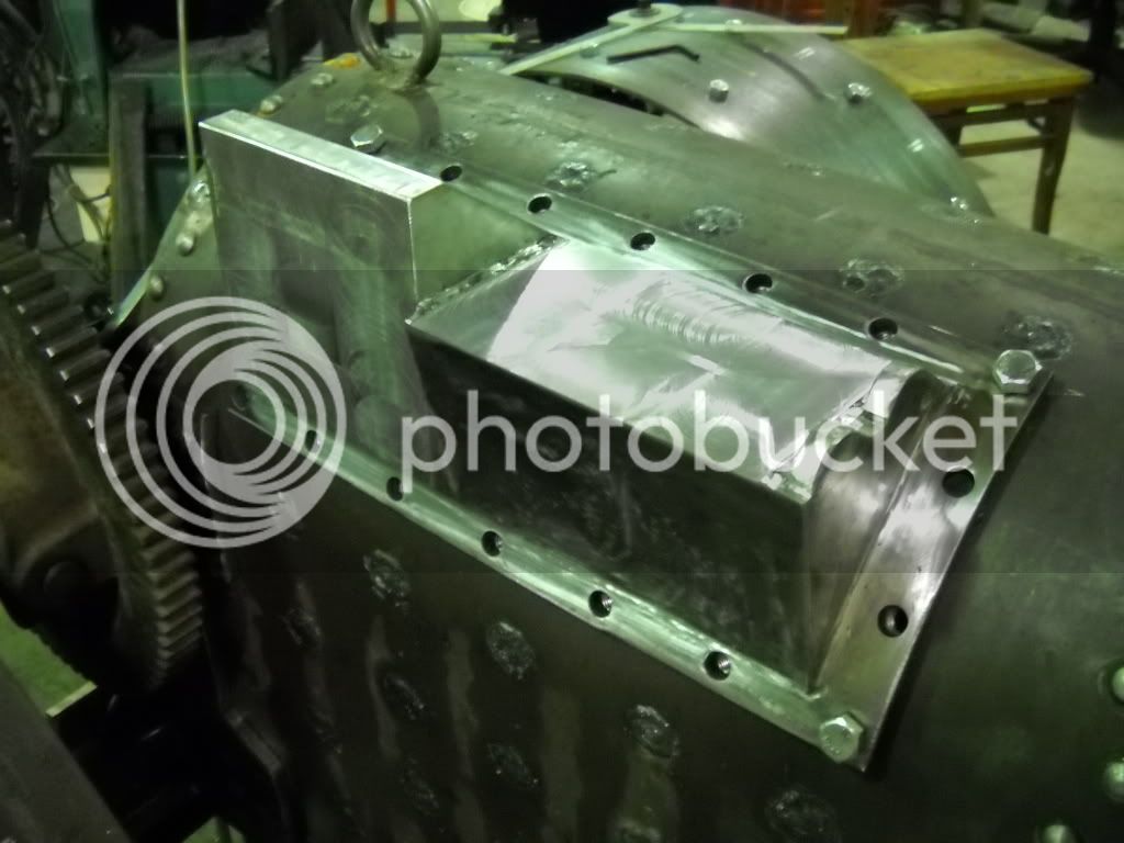
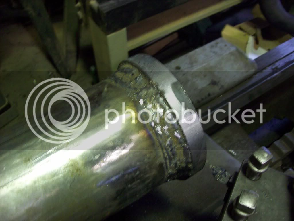
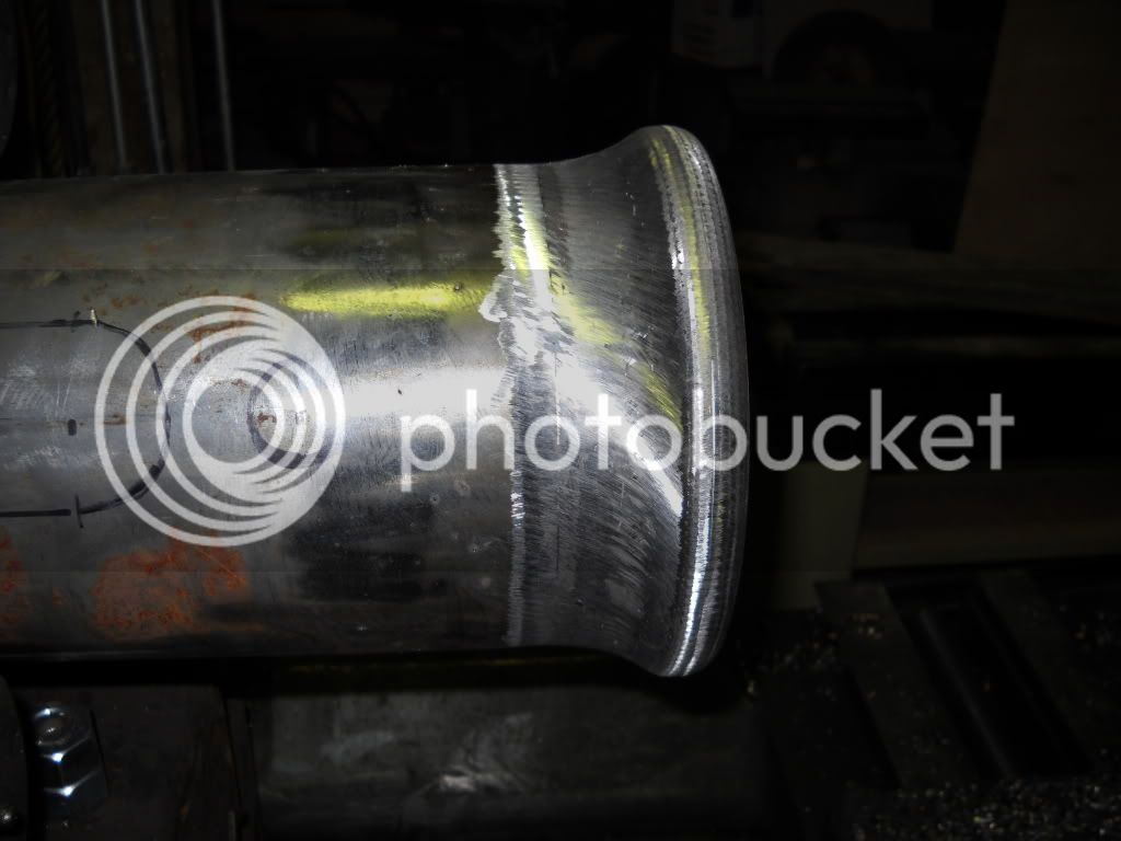
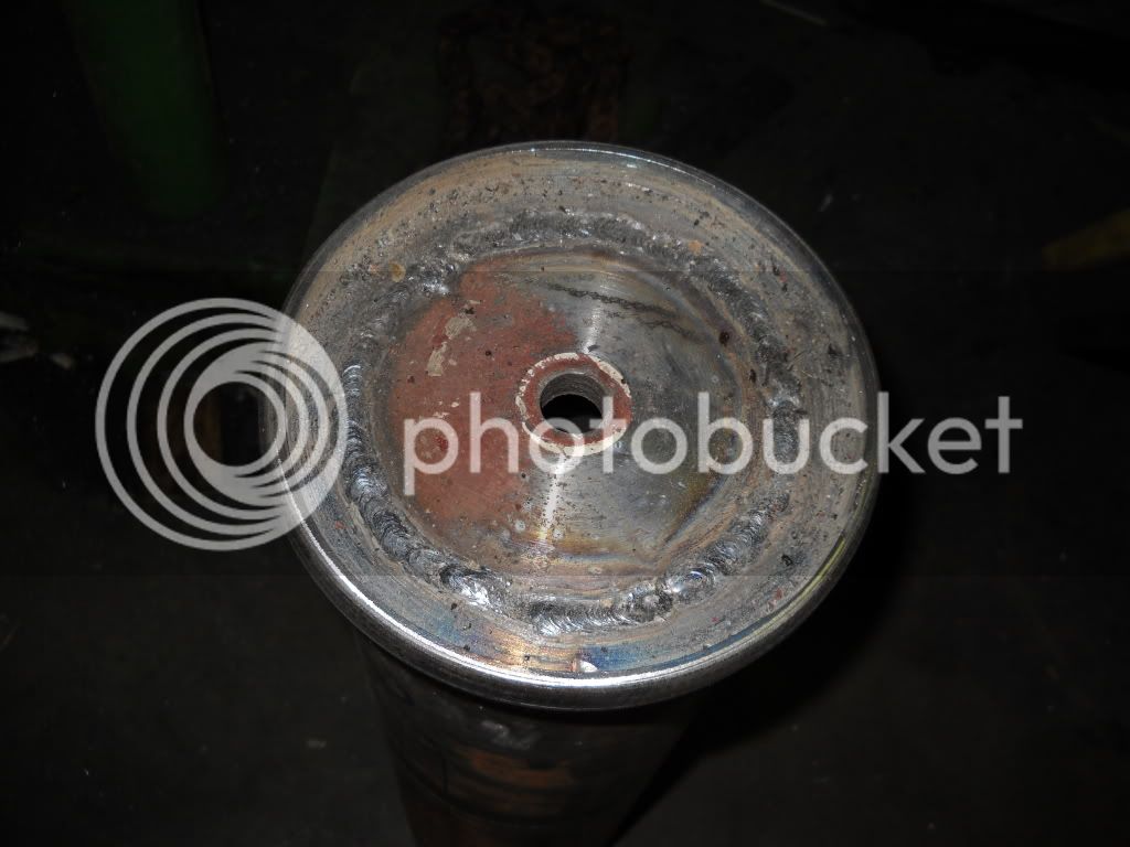
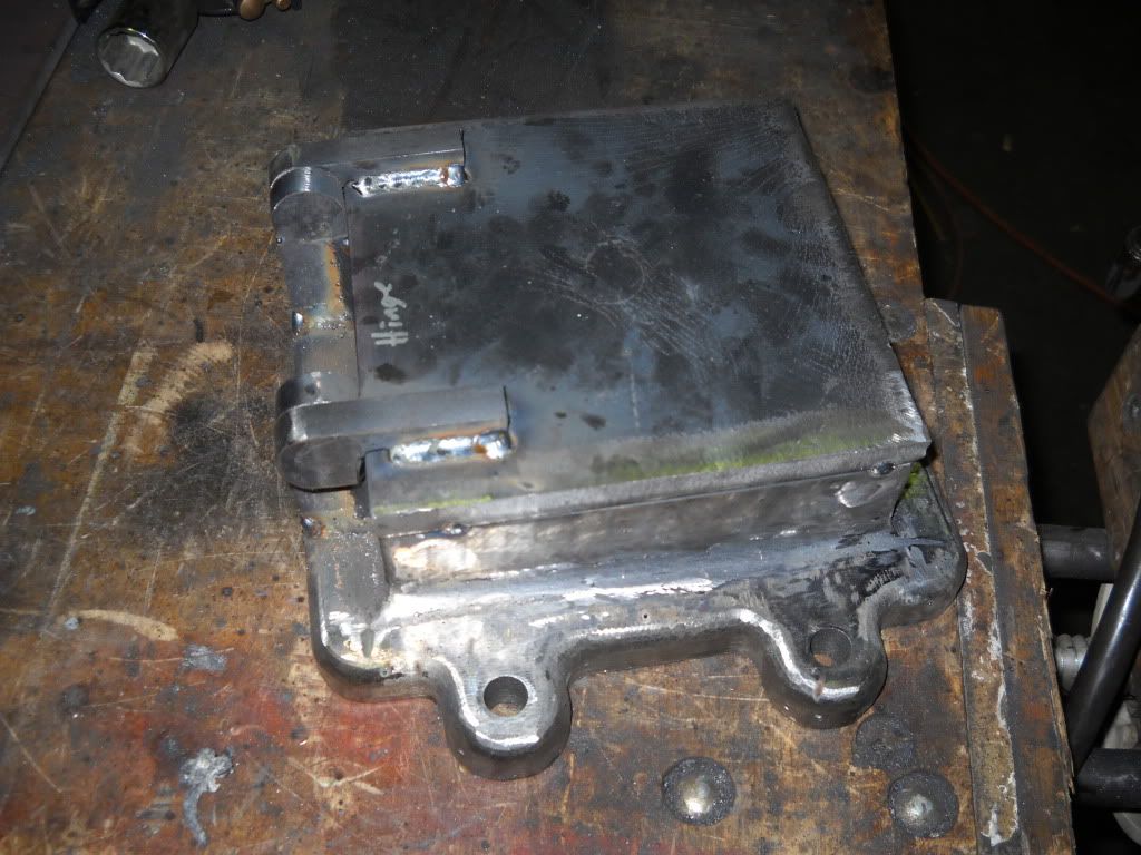
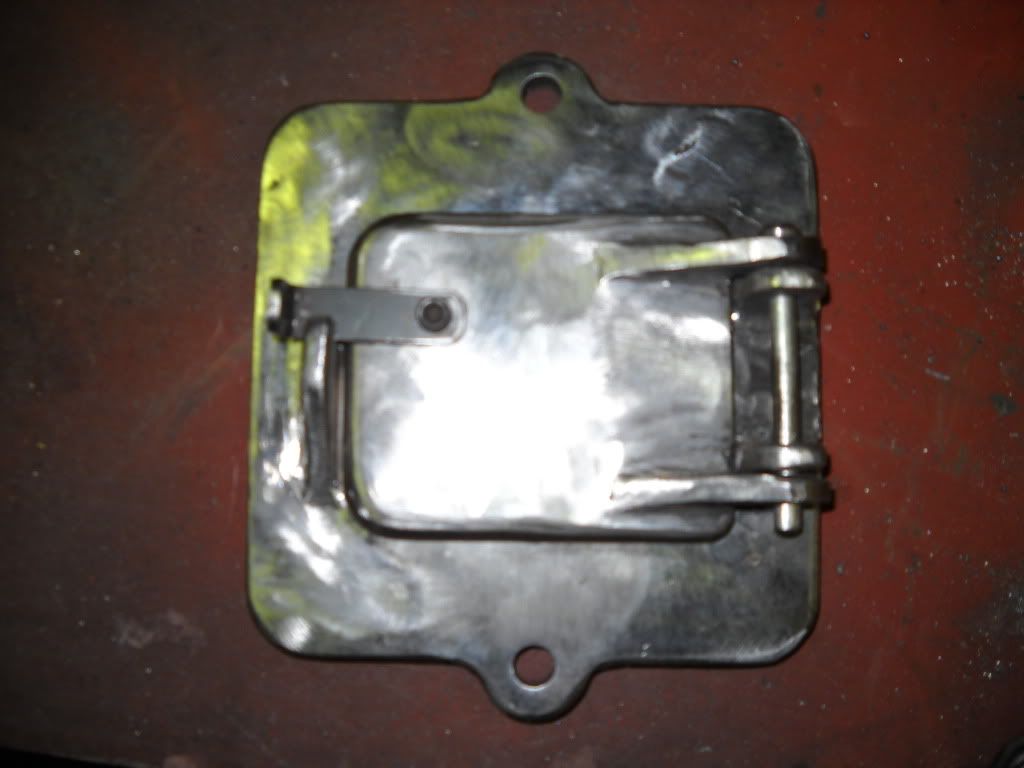
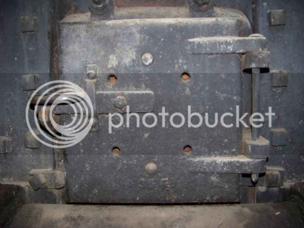
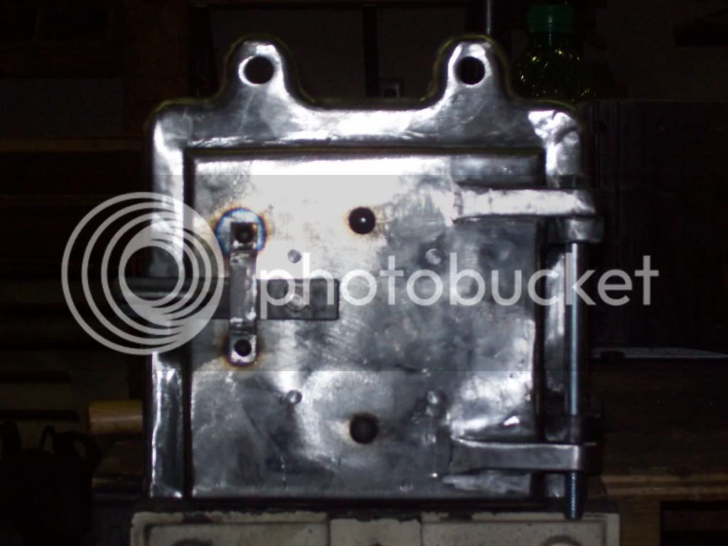
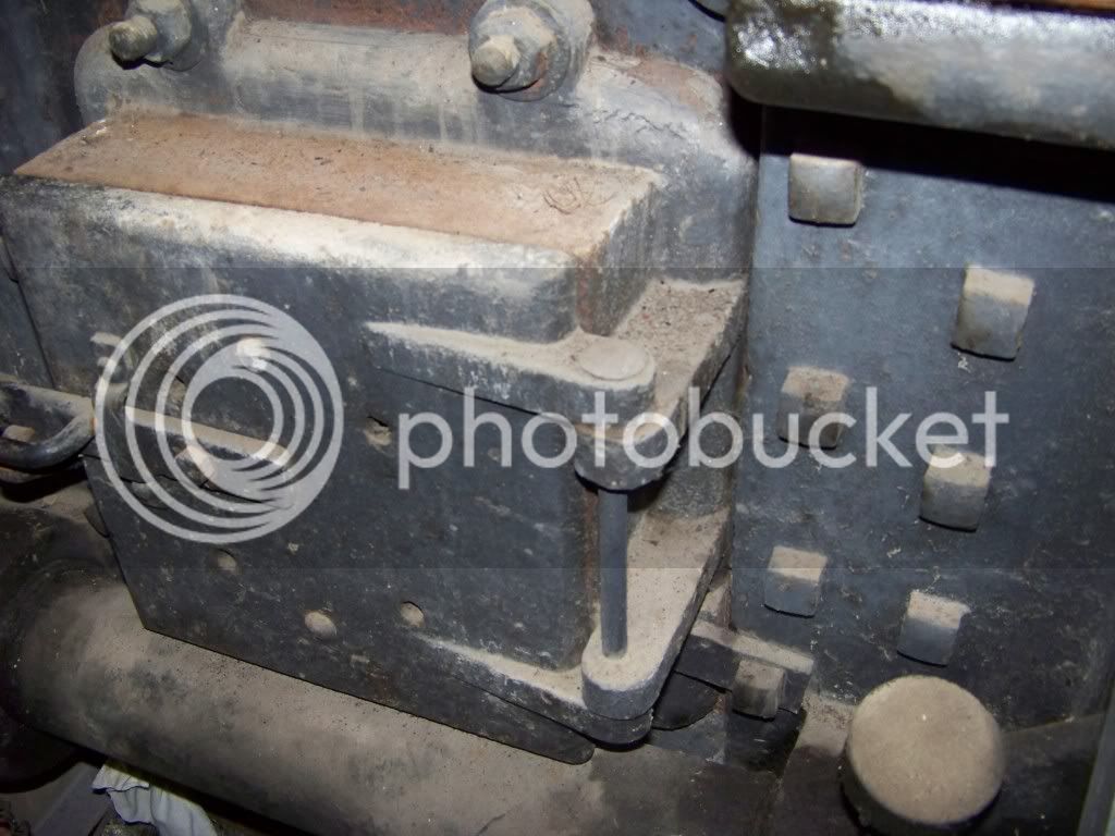
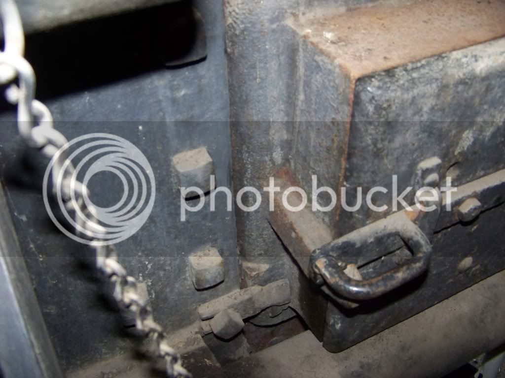
the hand hole covers

100_0581.jpg

100_0582.jpg

100_0584.jpg


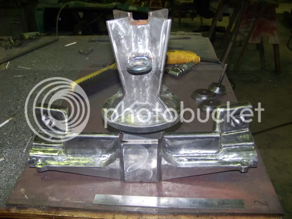
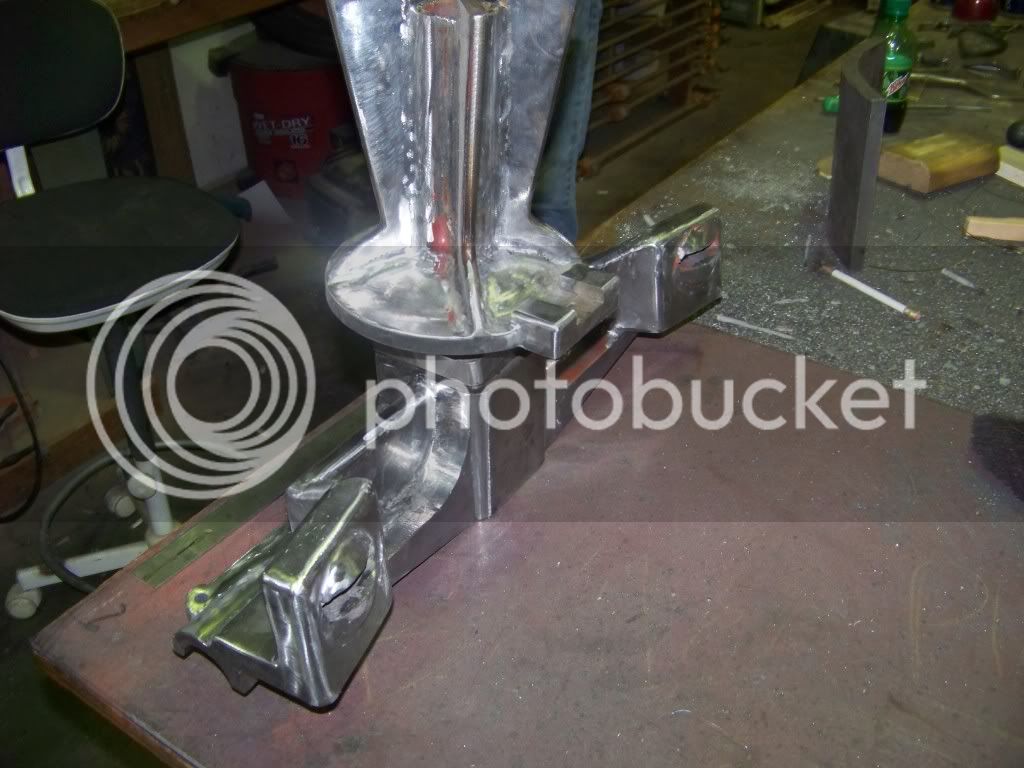
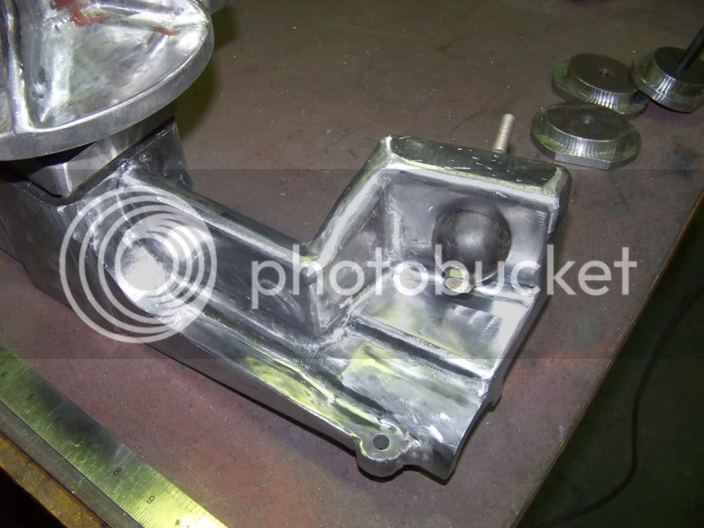
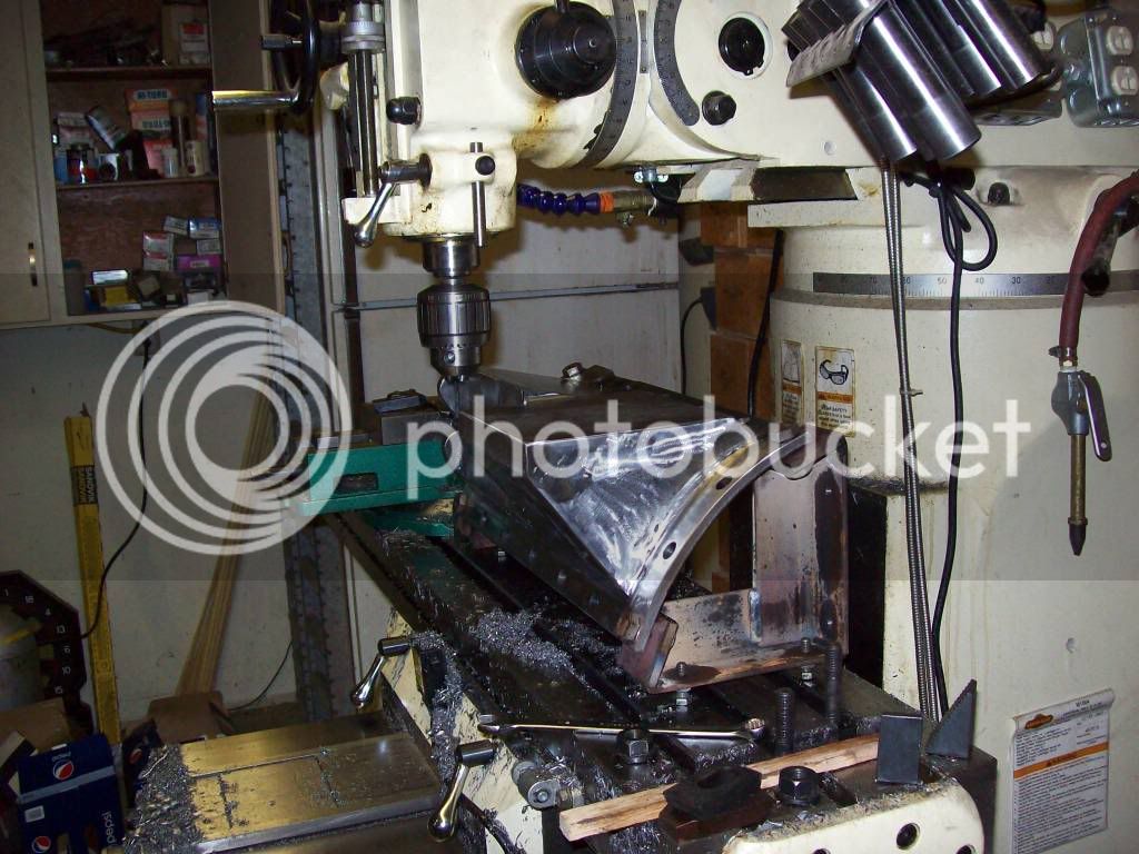
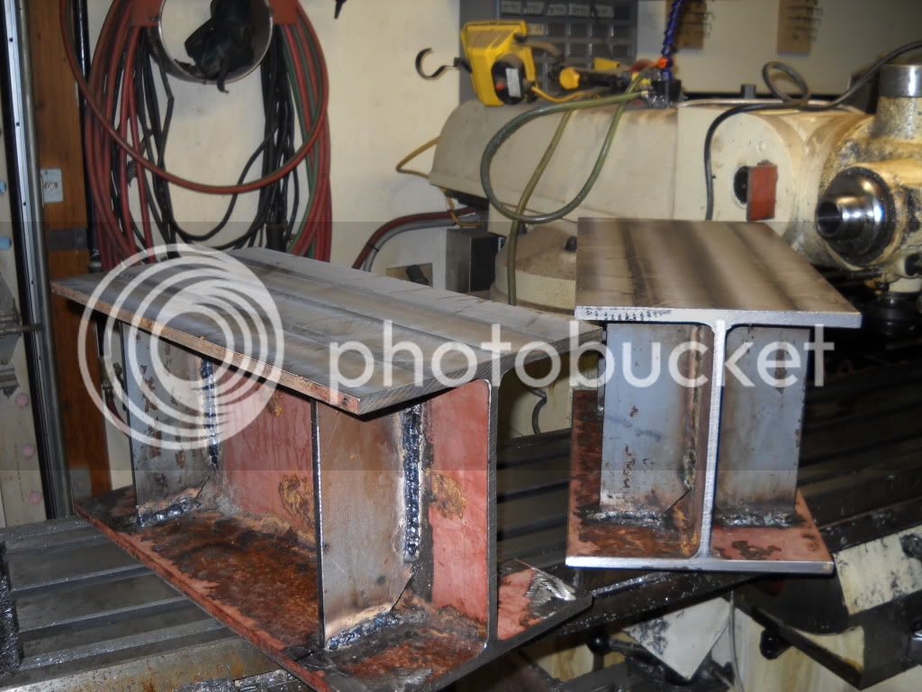
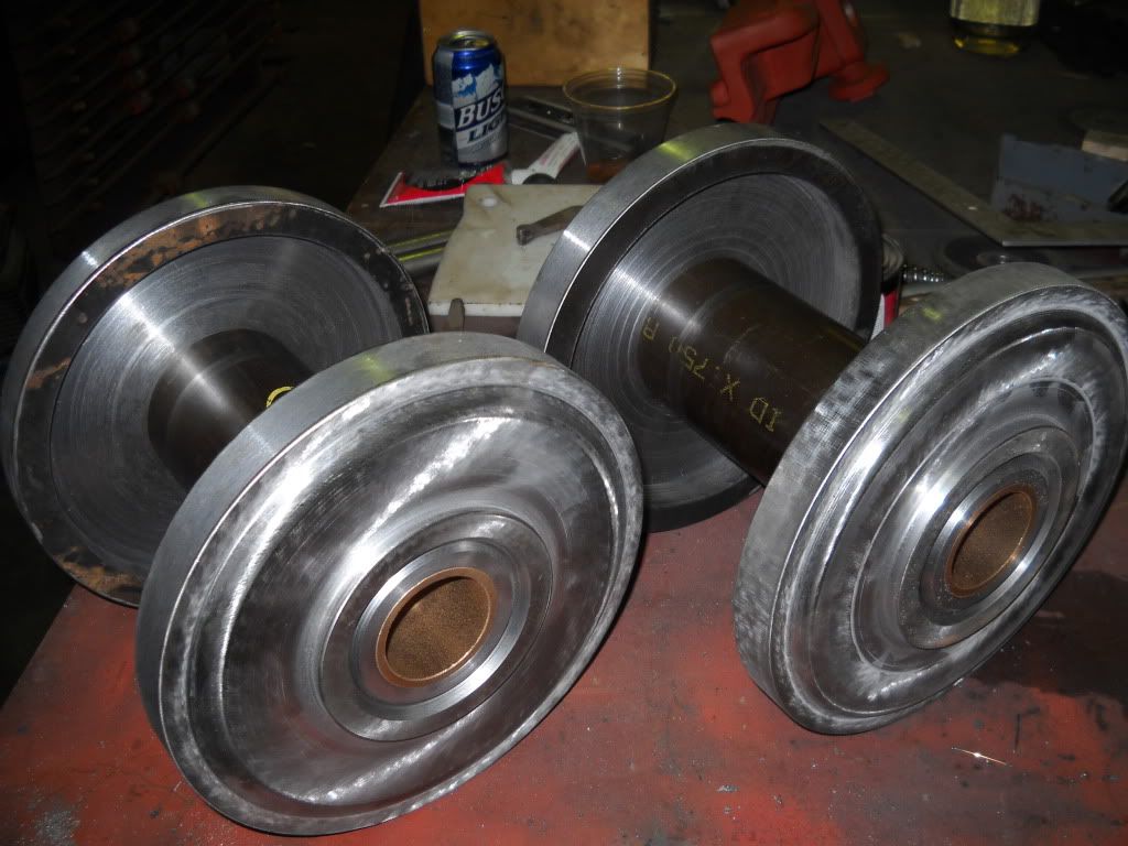
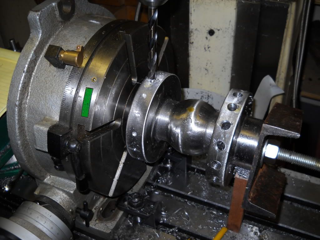
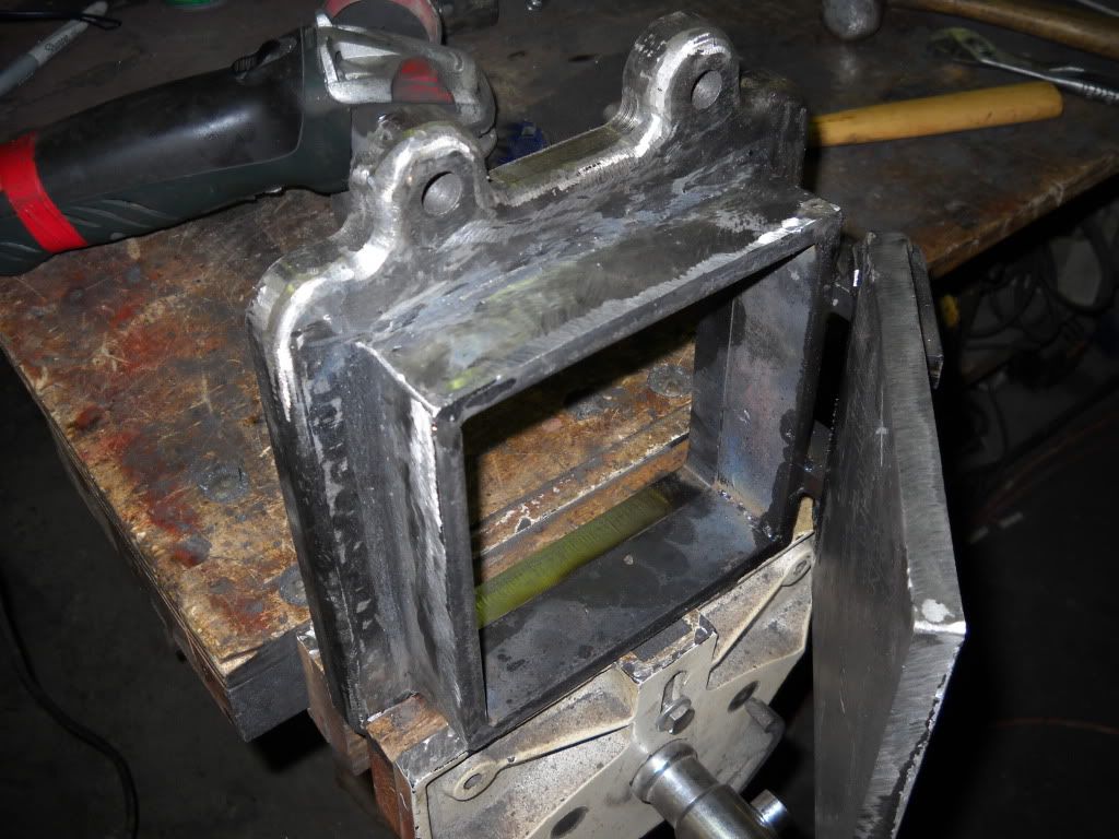
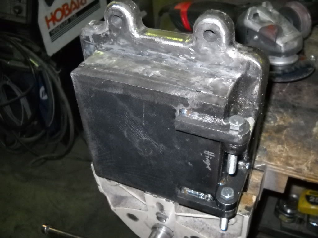
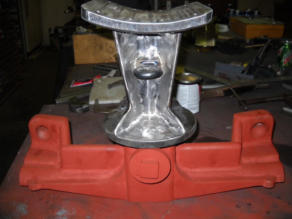
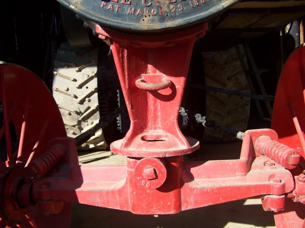
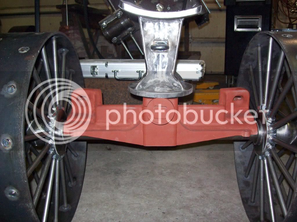
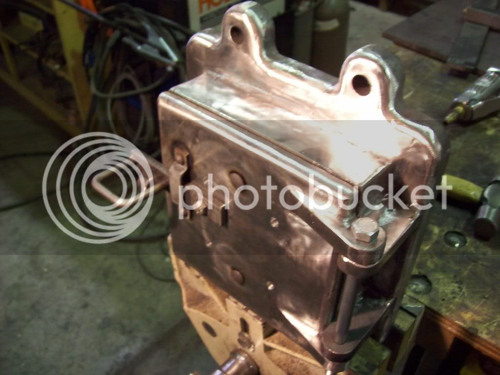
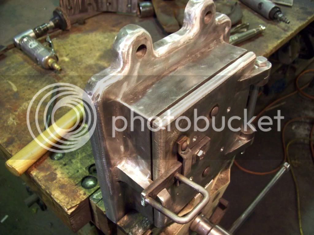
ive got the pedistal and axle support are getting real close, getting a nice smooth radius in all those tight corners is a real PITA, but if it was easy women and children would be doing it as they say. i might be trying to make it too good and making it alot harder than it has to be, i dont know.


well thats all for now, hopefully this will get more intresting as we get farther into it.
 
Looks like a heckuva lot of work done, to me! The pedestal looks great.
Thanks for the update on your project. It's nice to see it taking shape.

Dean
 
i didnt realise it had been so long since the last update, several new parts to show. the old man has been makeing better progress than i have, hes been out of work for awhile.

dads progress first

DSCN0043.jpg


corner brakets built and bolted on. bullgears, pinions and differential in place. bullgears are from an f-30 farmall tractor. differential and pinions are from a 620 john deere i think. by all apperances they mesh together perfectly, definatly good enough for this low of speeds.


DSCN0077.jpg


the rear hubs so far, flanges started out as plates, there about 9" dia, the little 13" lathe could swing them ok but it was really beating it up taking the corners off so he ended up using the big one which was overkill by alot, i think hes decided that he needs another lathe between the 13" and the 36" that he has now.

DSCN0082.jpg


here is one of the fron hubs in the old mans mill in the RT getting holes drilled for the spokes, 1/2"dia 32 per wheel.

now my progress

DSCN0069.jpg

DSCN0070.jpg

DSCN0074.jpg

DSCN0075.jpg

DSCN0076.jpg


the fire door that i started yesterday and my progress up to this afternoon.

DSCN0083.jpg


the side door to the firebox

DSCN0055.jpg


the not quite finished pedistal and axel support siting on the boiler which is upside down in this photo.

DSCN0080.jpg

100_0437.jpg


a pic of the finished (finaly) pedistal and axel support. theres a couple more views on my photobucket.


well thats about it up to this point, this sure does seem like it takes alot longer than it should but progress is being made.
 
I think you two fellows are making great progress. It's a big undertaking! The original builders had the benefit of a factory and foundry.
It's looking just grand. Your front axle assembly is a dead ringer for the original. Great work!

Dean
 
these are from last night

100_0386.jpg

100_0387.jpg

100_03962.jpg

100_0395.jpg

100_03982.jpg


i think the old mans wheelsturned out real nice

100_0426.jpg

100_0390.jpg


100_0427.jpg

100_0393.jpg


100_0428.jpg

100_03942.jpg


and i got the firedoor done
does anyone know the purpose of the deal thats rivited to the back of the door and the 4 holes through the door?


Still coming right along. The wheels look just great, and so does your fire door.

The riveted thing is to keep the door latch from spinning around so it doesn't catch on wood, etc., and so the operator doesn't have to fish around for it to re-latch the door.

The holes? Maybe just for draft, so the door doesn't smoke out the operator. Don't know for sure.

Dean
 
i think you misunderstood me bud, on the full size engines theres another plate kind of a thing that the 2 big rivits are holding on the back of the door, i dont wonder but if its not to make an airspace for insulation so the door doesnt get so hot, but i didnt ever really look that close.
 
You're making great progress on the engine. Fantastic work on the wheels.
gbritnell
 
hammers-n-nails said:
i think you misunderstood me bud, on the full size engines theres another plate kind of a thing that the 2 big rivits are holding on the back of the door, i dont wonder but if its not to make an airspace for insulation so the door doesnt get so hot, but i didnt ever really look that close.

I would agree, most probably for holding a fire brick for insulation - Nice BIG WHEELS. :bow:

Best Regards
Bob
 
Its probably for a baffle plate, this was a plate spaced off the door to deflect some of the heat, I'll post a pic of the one on my model later as photobucket is down for maintanance.

EDIT photo here

Jason
 
no new parts but we got to put what we got together, he still has to make the caps for the end of the axles to keep the wheels on and build the straps that connect the wheels and bullgears but other than that what you see is pretty much done.

DSCN0100.jpg

DSCN0103.jpg

DSCN0106.jpg

DSCN0107.jpg
 
Wow, very impressive!

Chuck
 
Very well done. Could you give us a few words on how you did the steam dome, particularly the dome and the flange where it meets the boiler? I don't see how you're able to move and shape that much metal.
Dennis
 
It sure is coming together!
I'd like to know how you did the dome, too.

Dean
 
Would spokes in those types of wheels be put under tension prior to welding? Just a thought that popped into my head.
 
the dome isnt what it appears, it was made starting with two square pieces of boiler plate that my cousin at the weling shop in town(a good guy to know for projects like this) bent into a semi circle with the break. the two halves where welded together and scribed to fit the curve of the barrel. the dome shaped cap is actually an 8" sch 80 pipe cap. after welding these pieces together and welding them to the rest of the boiler we(he had done everything else up to this piont) just took a piece of flat strap tacked it on the right side and started heating it up with the torch and bending and beating it around the dome, tack welding occasionally, and laped it over where we started. the flange around the dome and also on the throat sheet are just for looks the plates themselves are welded under them. the vertical lap was done by milling a plate long enough to go about 1/4 of the way around the dome on a taper from 1/4" to about 1/16" and bending it around the dome, so this piece is also non-structural. then he took and laid a big weld all around between the dome and flange and ground it to a radius, thus making a dome that appears to be made out of one piece but isnt.

diesel pilot- yes probably in full size practice they should be but this engine should weigh about 1/8 that of the full size engine and it had 3/4" spokes and this one has 1/2" so we got about 1/2 the strength holding up 1/8 the weight so i dont think its going anywhere, in case you where wondering why he didnt go 1/2 size i think its so he would only have to buy 1 die since the back wheels have 1", personally i would have made them 3/8" and bought 2 dies but i wasnt making them.


doesanyone know where to buy cleats for the back wheels, ive heard that some of them break easily
 
more pics

as always the old man first

100_0114.jpg


this is a bracket that supports the flywheel (right) end of the crankshaft as well as the idler between the crank pinion and the diferential ring gear. sorry he didnt take any pictures while putting it together, would just have been a bunch of plates tacked together though.
in this picture he is facing the surface that the crank bering bolts to, then he fliped it on the clamp jig he built and faced the surface that the idler bolts to so they would be exactally 90deg.

DSCN0116.jpg

DSCN0117.jpg


as for myself im starting on the crosshead guide but i guess i didnt get a picture so that will have to wait till tommarrow.
 
well i gess hes done with the bracket for now. hes moved on to steering gear. in case you dont know its done by rolling and unrolling chains around the shaft. the gears are from a cable hoist for stage equipment, there a little to big to be scale but there getting used.

DSCN0120.jpg

DSCN0121.jpg


i havent got much done this weekend. first thing saturday morining i bottomed out the cross slide on the lathe and broke the brass drive gear, again....., that took 3 hours to replace. i think im going to try and make some, i dont think that it would have to be prefect to work ok so i ground a cutter while the gear was out. then i laid the mill head over sideways and squared it up to drill bolt and dowell holes in the crosshead guide, only then realising that the closest i could drill to the table was about 8" above it. so i went back to the iron pile and found me some 8" H beam that i welded some gussets in and faced, i think they will work fine. measuring the four corners of each of them they are all +-.002".


the crosshead started as a seamless tube 5" ID 6"OD, i welded a piece of 1/2 X 1" strap around the end and built up behind it with the mig then turning it close and grinding it smooth to form a bell shape on the cylinder end. then i welded a plate in the end for the bolts to attach it to the cylinder.

100_0113.jpg


DSCN0118.jpg


DSCN0108.jpg


DSCN0119.jpg

my riser blocks
 
You guys are making great Progress!!! Thanks alot for sharing.
 

Latest posts

Back
Top