Upshur's opposed twin engine

Home Model Engine Machinist Forum

Help Support Home Model Engine Machinist Forum:

This site may earn a commission from merchant affiliate links, including eBay, Amazon, and others.
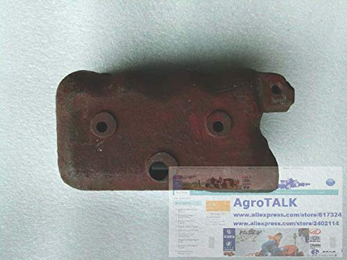
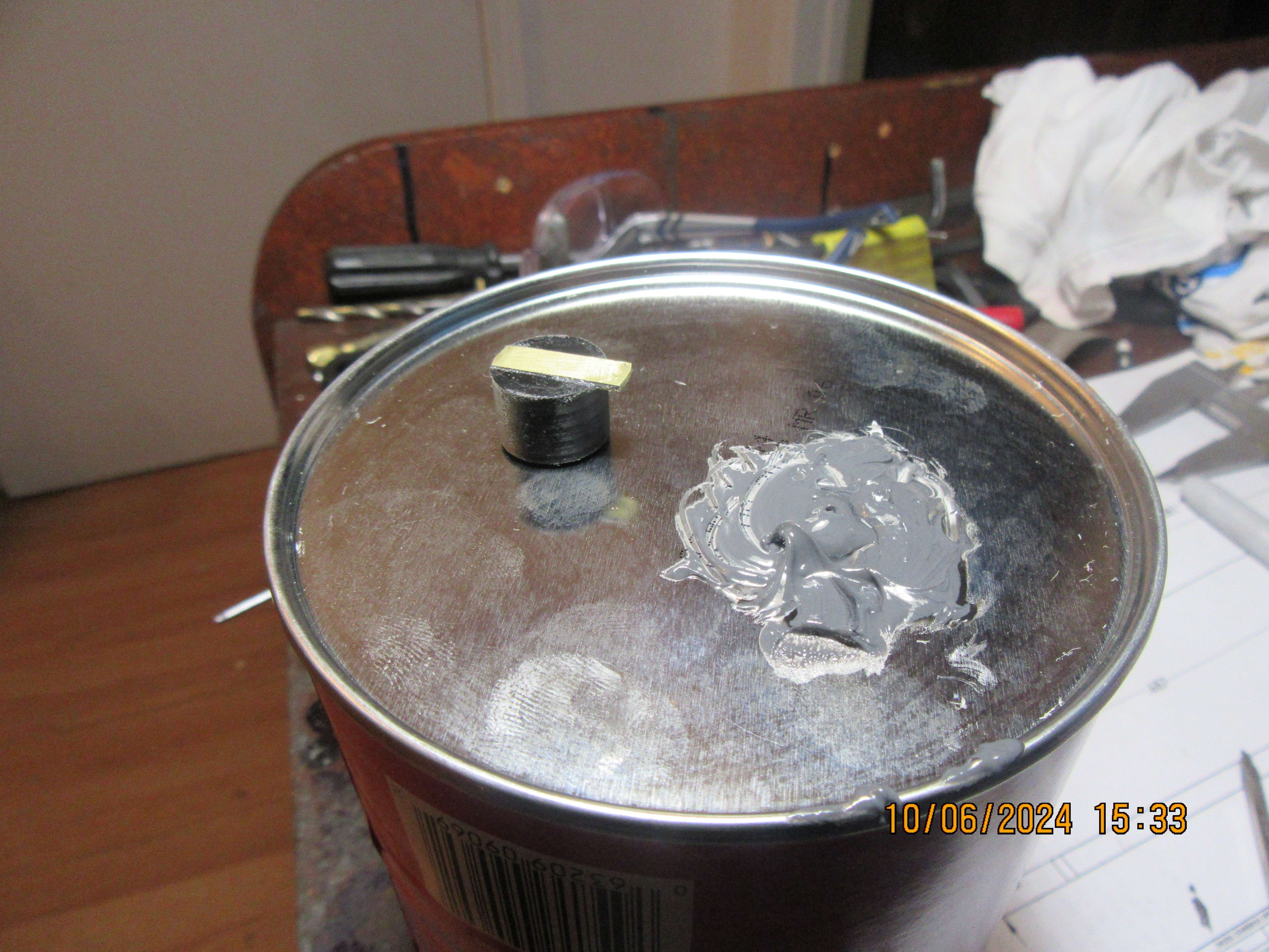
And this is all the work I'm going to do today. The brass has been sized to fit into the groove in the top of the rotor and glued in there with J.B. Weld. Tomorrow I will see whether or not the J.B. Weld is going to stick to the rotor.
xs5ExL.jpg
 
I use the clear silicon ones that S/S do/did, same as Gordons link. It is a spring inside the boot which grips the end of the plug. They also do the flat type but with your engine there would be a lot more risk of the spark jumping to where it should not as the flat plate is not insulated
 
S/S had what you ar3e looking for but he has retired. Apparently someone else has taken over the business

https://www.cncengines.com/index.html
Yes. Roy has retired to some extent, and now it is being carried on by a new fellow. Nice guy. He knows the ignition systems.

Brian- I would doubt that CT would have anything for a plug of that size. Maybe??

I know cnc has them

Sid
 
I will check out some of the electrical supply places around Barrie. That connector doesn't look like it would be difficult to source, but I'll find out.---Brian
 
The flat clips are difficult to source even the larger CM-6 size and why I buy them from S/S in America as not available in the UK or from far eastern suppliers.

With no insulation on the flat clip there is a risk of the spark jumping to your push rods and not going to the plug. Why not eliminate another reason the engine won't run before wasting time buying the flat type connector. They do look the part on a period engine where there are no bare metal parts nearby but you have neither.

This will stop the spark jumping, nice and small to suite the 1/4 x32 plugs unlike the RCexl metal ones.

250bpsm.jpg
 
Last edited:
I have been somewhat successful with 3D printing them. The problem is that the 3D filament is not as flexible as the silicone so different 1/4-32 plugs are different enough that you need different configurations. Steve Huck who sells 1/4-32 plugs has used a modified air fitting.
 
You can buy more flexible filement but would have to find a use for the other 99% of the drum
 
I do like the look of those a lot better. Maybe I will give Roy a call and see if he still has any. Somewhere on one of the forums I attend, someone posted plans for a three piece mold to make your own very similar sparkplug boots from silicone. Does anybody have a link to that thread?---Brian
 
And here a (at an almost microscopic scale), are the rotor shown in place and the distributor cap setting on top of a pill bottle. That center bolt on the distributor cap was supposed to be a #2-56, but I stripped the threads, so went up to a #4-40 stud instead. The distributor cap is 1.060" diameter.------------And---I think that is all of the stuff I need to build for this engine!! Next will be the electrical wiring, (There isn't much of it) the heartache of getting the cam timing set and seeing if it runs.
0Aapuv.jpg

kw5bes.jpg
 
Last edited:
The throttle lever on this engine is a bit funky. The only thing holding it in place rotationally is God and the plastic gas line. I have designed a "throttle keeper" (the yellow part) which clamps onto the near side gas line with a #5 shcs.. This throttle keeper holds a #10 shcs which is drilled for a very strong little spring (you don't see it here), which bears against the end of the throttle screw and holds it wherever you set it at. There is a rubber o-ring on the far side of the carburetor body as per the original design, and although it does keep the throttle screw from falling out of the carburetor, it really doesn't do much to hold the rotational position of the throttle needle.
zUzeIm.jpg
 
The O ring grove is set close enough to the shoulder that the side of the ring is less than 0.375 from the shoulder and that should provide enough friction to stop the throttle moving. So should not need those extra parts.

If you have gone too deep with the o ring groove then a simple shim washer under the shoulder on the other side should tighten things up.
 

Attachments

  • oring.JPG
    oring.JPG
    51 KB
Last edited:
Brian, I do still have some of those 1/4-32 boots. Also, Dan has had the large CM-6 clips made and I think he is also working on the 1/4-32 clips. I still have the die set from Bruce Satra for the small 10-40 plugs which will be available to Dan. We were concentrating on the CDI but I will make anything available that Dan would like to keep in stock. All of the Satra distributor parts are still available. I've retired so I can get some engines built, so far without much success, but I'm not planning on going away any time soon. I'll be at the 2024 Indiana Show this year.

Roy
 
And there it is boys and girls!!! a "throttle lever position fixer". There is a coil spring inside that #10 shcs that presses on the head of the throttle screw, keeping it from moving randomly. It is easy to turn it if I want to, but will not turn "by itself". I think that was the last thing I had to build on this engine.
kPT6tt.jpg
 
Brian, I do still have some of those 1/4-32 boots. Also, Dan has had the large CM-6 clips made and I think he is also working on the 1/4-32 clips. I still have the die set from Bruce Satra for the small 10-40 plugs which will be available to Dan. We were concentrating on the CDI but I will make anything available that Dan would like to keep in stock. All of the Satra distributor parts are still available. I've retired so I can get some engines built, so far without much success, but I'm not planning on going away any time soon. I'll be at the 2024 Indiana Show this year.

Roy
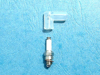
Hi Roy--I need two of the 90 degree sparkplug boots for the engine I am currently building. The sparkplugs are very small 1/4"-32 plugs (I may have bought them from you) the porcelain measures 0.180" diameter x 0.350" long and the brass part on top of the porcelain measures 0.160" diameter x about 0.10" long. I will need sparkplug wires 4" long attached to each boot----I will look after terminating the other end of the wires. Please shoot me a price for this [email protected] -Brian Rupnow
 
It's the FINAL COUNTDOWN!!! I am still confused about the cam positions relative to each other. The cams, gears, and crankcase are as Upshur drew them. (I did add a hub onto one side of the cam gear to lock it to the shaft.) I am running the engine the opposite direction to what Upshur suggested. The Upshur drawing does spell out cam lobe separation of 101 to 102 degrees. That shouldn't change no matter which way the engine rotates. The cam closest to the cam gear is Loctited to the shaft and positioned relative to the cam gear As you can see from the picture of the engine, I have about 0.2" clearance between the other cam and the inside of the crankcase.---I can make a new cam with a slightly larger diameter hub and put two set screws in the hub. This will let me position the second cam lobe 102 degrees from the other fixed cam lobe. I only have two choices then. If it doesn't run with the second cam offset one direction, then it should be a simple task to loosen the set screws and rotate that cam 102 degrees in the opposite direction. I don't usually confuse myself this badly. Getting old.---
KDAJmt.jpg

vnJUtv.jpg
 
So turn the flywheel so one of the intake valves is at full lift of it’s valve an note the position of the flywheel. Now turn the flywheel the opposite way that you want the engine to run ~ 202 degrees and set the exhaust cam lobe at max lift of it’s valve and secure to camshaft (of course, on the same cylinder side that you first set the intake valve at max) . That will establish the valve timing, After that, adjust your cam gear so the a piston is at top dead and it’s cam lobes are right between their peaks. That is, the exhaust should be closing and the intake should be opening. That may not get to the exact settings but I don’t worry about a degree here or there and it should run. Easy for me to say.
 
Last edited:

Latest posts

Back
Top