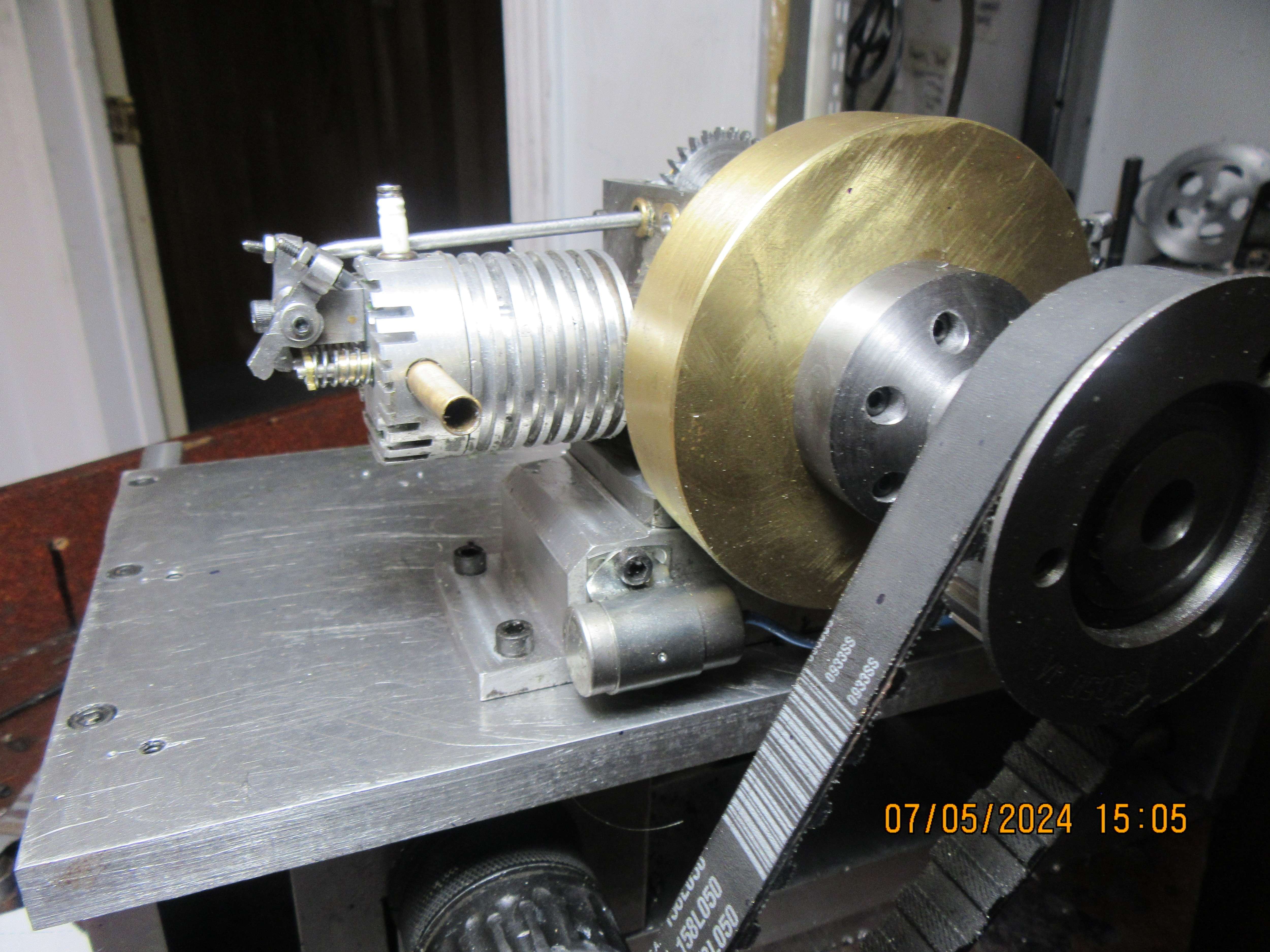
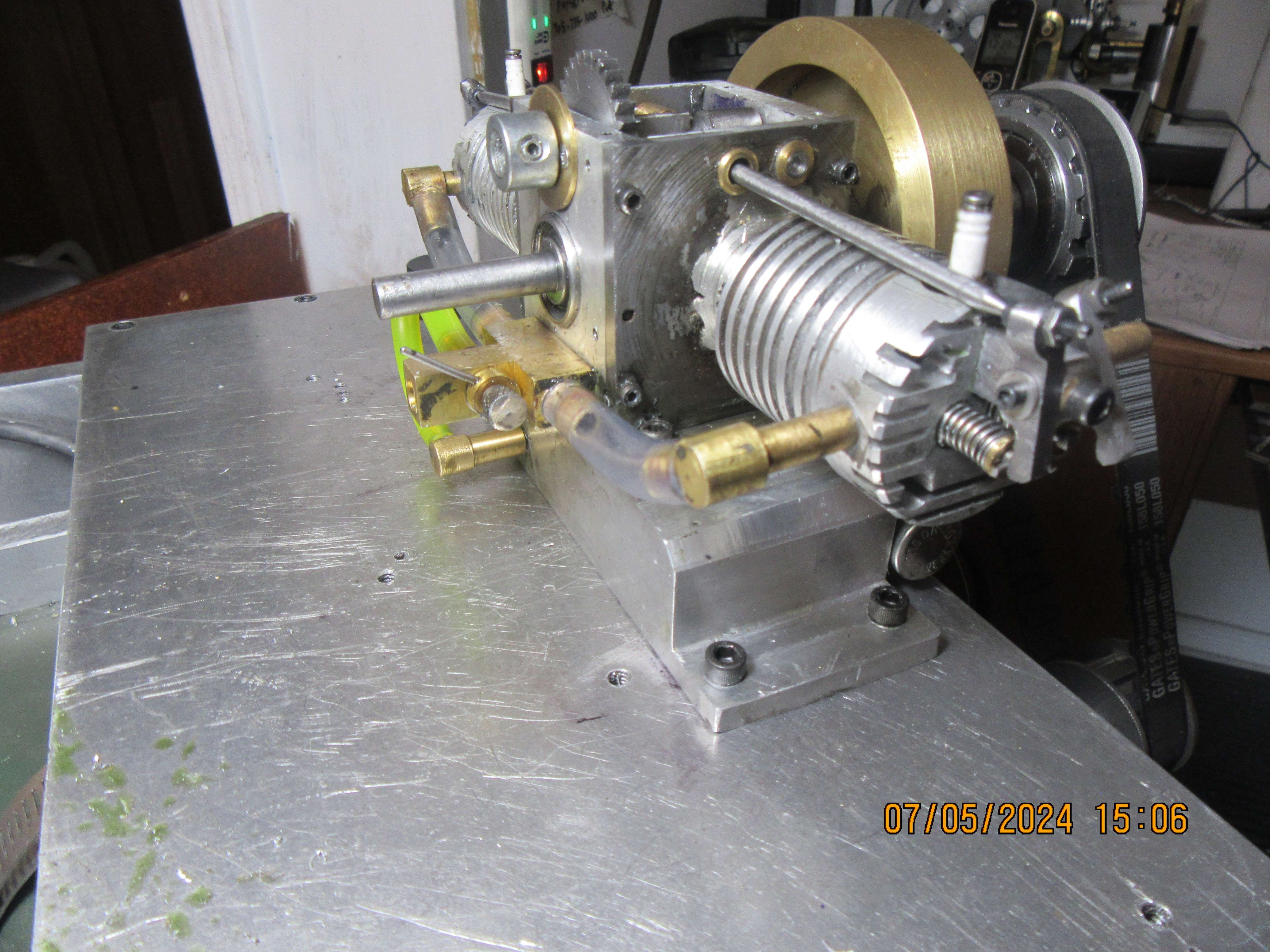
Upshur's opposed twin engine

Home Model Engine Machinist Forum

Help Support Home Model Engine Machinist Forum:

This site may earn a commission from merchant affiliate links, including eBay, Amazon, and others.
I'm having a hard time getting my head around this.---
Simply - because : where one cam operates the exhaust valve on both cylinders and the other cam operates the intake valve on both cylinders."
You just think of it as the engine on one side and when you align the lobe for that engine it will be exactly aligned with the other engine on the opposite side.
 
Hi Brian!

Great job you are doing with your engine!
I have been trying to build valves and valve seats for a four stroke engine that I am building.
I was unsuccessful, as the valve doesn't seal properly.
Could you show how you make them?
 
Today was kind of a write off type day. I went for my last physio appointment and was told that I had "progressed nicely" and didn't need any more physio appointments. I had it confirmed by another source that the angle between the two cams is indeed 105 degrees on this engine. I set the assembled engine up on my test bench, filled with oil and drove it with an electric motor for 20 minutes to get rid of any tight spots. I cut all of the pushrods to finished length and installed them, and set the valves to 0.005" clearance--not sure yet if I have to put relief slots in my cylinder heads for the push-rods or not. I read thru the instructions from Upshur once again about the distributor and decided that tomorrow I would buy some #2-56 threaded rod or at least some brass bolts with long threads that I can cut off and use for distributor terminals. I still have to put a keyway in my flywheel and in the crankshaft end that the flywheel sets on. I also have to set the engine up on my starter stand and drill and tap four holes to bolt the engine to it. That's probably enough work to keep me occupied tomorrow.----Brian
 
Gordon confirmed it was 102 Deg not 105

5 Thou is a lot of clearance for a small engine. You are unlikely to get the duration of valve opening with that much clearance.
 
Today, it didn't take too much to wear me out. I drilled and tapped the engine sub base to hold a condenser for my ignition, drilled and tapped my starter mechanism top plate for the Upshur engine bolt pattern, milled a keyway in the crankshaft and cut a keyway in my flywheel. That doesn't sound like a lot, but I'm tired out now.
eTUezu.jpg

ShykeZ.jpg
 
Great to see you back in the shop! I always look forward to your posts.
Scott
 
Thanks Scott--No work today---All my aches and pains have caught up to me today, and I'm hobbling around like somebody's old granny. I still have to cut some clearance grooves in the cylinder heads to clear the pushrods, and time the cams. I called my nut and bolt guys yesterday and they don't carry any bolts nor threaded rod size 2-56 so I can either attempt to make my own---questionable.--They need to be made from brass, for the distributor so I will wait until Monday and try a different nut and bolt store (we actually have two such in Barrie).
 
Thanks Scott--No work today---All my aches and pains have caught up to me today, and I'm hobbling around like somebody's old granny. I still have to cut some clearance grooves in the cylinder heads to clear the pushrods, and time the cams. I called my nut and bolt guys yesterday and they don't carry any bolts nor threaded rod size 2-56 so I can either attempt to make my own---questionable.--They need to be made from brass, for the distributor so I will wait until Monday and try a different nut and bolt store (we actually have two such in Barrie).
Try a hobby shop.
They usually have screws of that size.

Sid
 
I couldn't let the entire day go by without doing something.----So----I milled grooves in the cylinder heads to clear the pushrods. You can't see what I have done, because the grooves are hidden by the pushrods. I can slide a piece of printer paper between the heads and the pushrods without it jamming up, and a miss is as good as a mile.
 
I was going to suggest an RC hobby store. For sure they would have steel 2-56 fasteners & threaded rod but I'm less confident about brass. They are not difficult to make in the lathe with a die & then you have control of other features if necessary. I made M3 pushrod adjusters from O1 for my radial. Brass would be easier yet.
 

Attachments

  • SNAG-06-07-2024 10.46.41 AM.jpg
    SNAG-06-07-2024 10.46.41 AM.jpg
    199.5 KB · Views: 0
  • IMG_3714_edited-1.jpg
    IMG_3714_edited-1.jpg
    231 KB · Views: 0
They should not be hard to make, turn a bit of brass down to size and run a die down it in the lathe. Brass is easy to machine and unless your die is blunt will thread easily. If I can do it down to 0-80 and smaller on a similar lathe to yours it should be easy doing 2-56.

Did these in the week from 303 Stainless at M2 they are just a bit smaller than a #2
 

Attachments

  • 20240702_144312.jpg
    20240702_144312.jpg
    2.5 MB · Views: 0
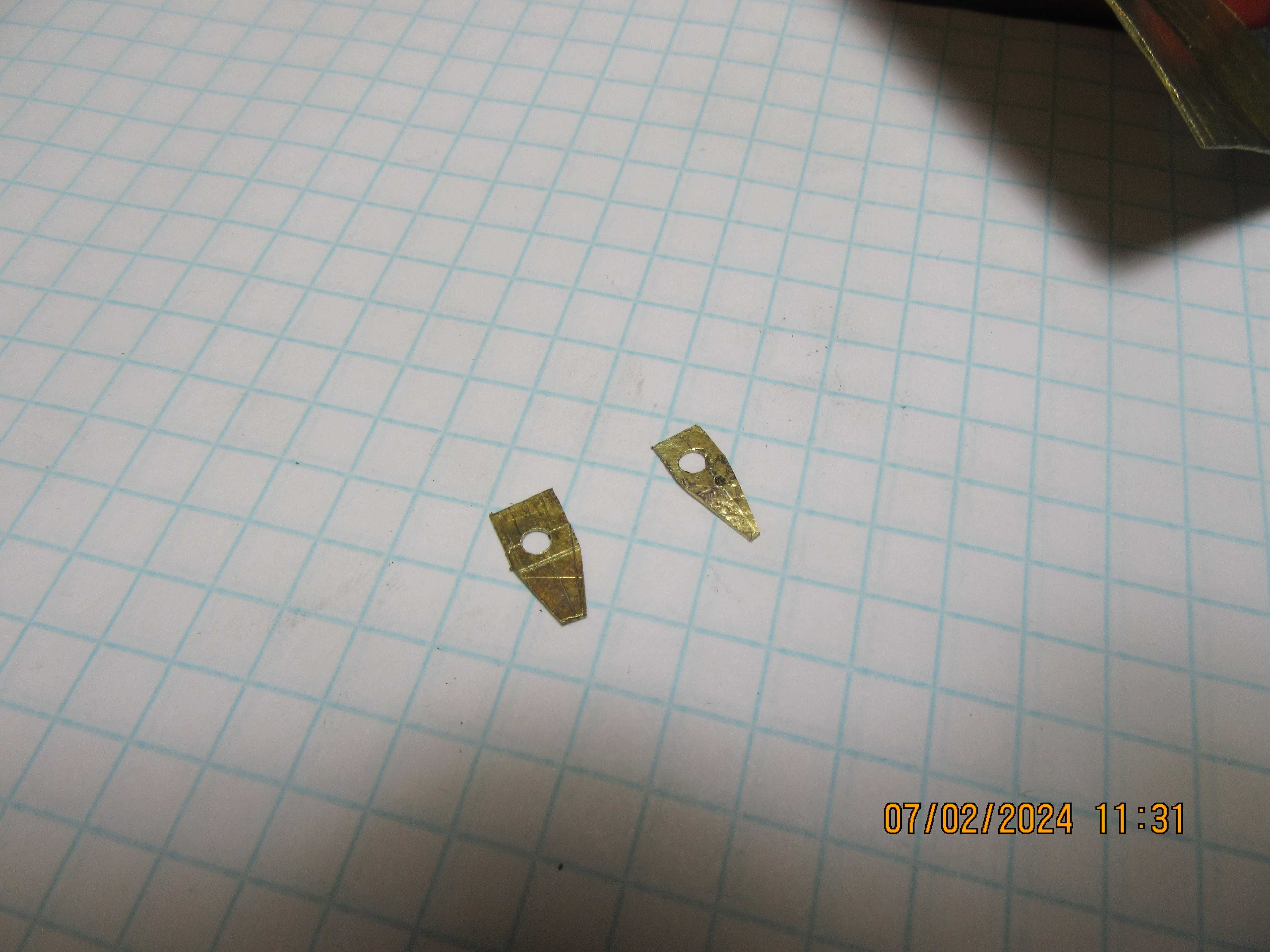
These two rather horrible little parts are "oil slingers" which bolt to the underside of the con rod caps and sling oil all over the inside of the crankcase when the engine is running. They are horrible because non of my machinery is really intended to make parts this small. So, by default, they are made with sheet metal "snips" and are irregular and ugly. The only good thing about them is that they are down inside the engine where nobody will ever see them.
78F5v0.jpg
Hi Brian,
Sure glad to see you at it again. I see these parts would make your list of parts you can make on your bench top cnc mill if that project is still being kicked around. The picture I sent 3 of the angled brass parts are connecting rods for a J. Ridder Euro 50 micro stirling engine I’m in the midst of building, the rectangular part is a bearing support & the other silver connecting rod was an experiment on how thin of material I can machine. It is .004” thick shim stock mild steel since I didn’t have .003”.
I see you have lots of people rooting for & are glad you’re back, you keep us interested.


George
 

Attachments

  • IMG_7190.jpeg
    IMG_7190.jpeg
    95.3 KB · Views: 0
Jason--I may be having a total mind fart here, but I've been messing around with cam angles all afternoon and I simply can not see how 102 degrees lobe separation on the cams can work. If the inlet valve begins to open when the piston is 15 degrees before top dead center, and the exhaust valve begins to open when the piston is 40 degrees before bottom dead center, then I don't possibly see how 102 degrees can work. I'm not usually this thick, but I'm missing something.---Brian
 
Look at the color diagram that I posted before. That shows the total cycle. What you have to look at is the 102 x 2 = 204 is the cycle, not the 102. The 102 is only because the cam turns at 1/2 the crank rotation. Forget 102 and think 204.
 
Maybe its an optical illusion of Brian's cam picture taken at an angle, but I am having a tough time understanding the timing. Just as a comparison, the horizontal opposed 2-cyl Boxer I'm working has a 4-lobe camshaft, 1 per lifter.
1720589117339.png


I think boxer configuration means both left & right pistons are at TDC at the same time. But, at least in my case, the firing is alternate left/right 360-deg apart on CS angle. The left picture shows the cam layout with red (EXH) and green (INT) lifters aligned to the cam. EXH leads INT as per rotation direction. The right right picture shows the same view looking obliquely. The right lifters are in the valve lift zone on the cam. EXH is almost closed and INT is just starting to open. On the left side, 180-deg apart (=360 CS degrees) the lifters are in the 'valve closed' zone (compression or power). So far so good?

1720589084187.png
1720589148063.png


Now when I look at the Upshur, I see the lifters are straddling 2 common lobes phased apart. I've sketched dash line what I think are the cam peaks.
But it almost seems like one lifter is in valve open (action) while the other is in valve closed (dwell) at the same time. Again, this may be an optical illusion. As long as the physical timing is checking out in the correct crankshaft/camshaft direction then it must be correct. Or... maybe I'm misunderstanding what I'm about to build haha.
1720589825769.png
 
Lobe seperation is always measured at the cam. Lobe center line exhaust to lobe center line intake. Overlap is different and measured at the crank and is the time both valves are open. Crank measured overlap with a degree wheel will be changed depending on valve clearance etc.
 
First thing to say is that the images Gordon posted are from more than one engine. But the 102 deg is from the Upshur, the timing diagram just shows how the 102 is derived but is close enough at 102.5.

As has been said just think of the cam as that for a single cylinder engine and set it up as you would for that. Upshur made it simple by just having the two shared cams, set one side up right and dthe second will take care of itself

Lets take the angles of some single cylinder engines to show the 102deg is rightMechanics

Midget from Popular mechanics 117deg
Gassie that I have just posted here looks to be around 110deg
Bobcat & Jaguar that Brian has based all "his designs" on 102.5deg
nemett Lynx 105deg.

So based on those figures the 102deg of the Upsure is just about the same as Brian has been setting up all his other engines so why should he think this one is any different.


If we take the 4-stroke cycle in simple terms of 180deg crankshaft rotation each for Intake, Compression, Power and Exhaust it can be seen that the exhaust should open at 3 x 180 or 540 deg of crankshaft rotation ignoring laps at TDC and BDC.

Cam rotates at half the rate of the crank so that 540deg becomes 270deg. On our engine that means the cams need to have their peaks 270 degrees apart. So 360-270 = 90deg, by the time we have added the overlaps at TDC and BDC that 90deg becomes the 102deg of this engine.

What is important is the rotation of the cam and which cam leads. Brian will need to alter the orientation of the cams to suit his reverse running

Peter
The Upshur Cam operation is no different to the Cam you shows, it just depends where the particular tappet runs and what valve it's rod goes to. If you were to swap over the middle two cams and also move their respective push rods you would get exactly the same as the Upshur. The Angle in Brian's photo has not yet got the valves set to the correct 102deg angle.
 
If the inlet valve begins to open when the piston is 15 degrees before top dead center, and the exhaust valve begins to open when the piston is 40 degrees before bottom dead center, then I don't possibly see how 102 degrees can work. I'm not usually this thick, but I'm missing something.---Brian

You are mixing crankshaft angle (40 and 15) with camshaft angle (102). And also mixing teh timing diagram from one engine with the cam angle of another. As camshaft is half the rate then 102 becomes 204.

Then add in the fact the cam rotates in the opposite direction of the crankshaft. So 360 - 204 = 156 crank degrees or 78deg of cam

So ignoring overlaps what you have is TDC when valve starts to open is 0deg of cam, first BDC is 90deg of cam, next TDC is 180deg of cam then as you come down to the next BDC which would be at 270deg of cam the exhaust has actuated (180 + 78) at 258 deg of cam
 
Here you go. Cams on this engine maybe 110deg apart but as they are out in the open it shows that is what works.


If you are not getting that sort of result then first check which cam is leading as your reversed crankshaft direction will alter the 102deg to the opposite way round. So that first image of Gordons will want the cam near the short end of the shaft pointing towards you and the one near the long end away.
 

Latest posts

Back
Top