rodw
Well-Known Member
- Joined
- Dec 2, 2012
- Messages
- 1,146
- Reaction score
- 341
This thread might take a fair while to develop. Its been 12 months in the making already. My Arduino Rotary table controller project got me interested in CNC but I did not want to do the obvious and convert my mill to CNC. I eventually got interested in CNC plasma cutting and I started about 12 months ago by cramming the electronics into an old Plasma machine case complete with a Torch height control. There are 3 layers of electronics in the case.
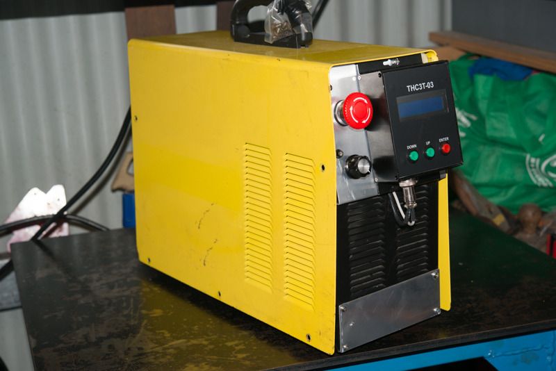
I got very disollusioned becasue my cheap plasma cutter died and the parallel port Break Out Board refused to talk to the PC.
So it sat on my desk for the next 10 months or so until one day I remembered how much time and effort went into it so I decided to kick start the project again. So in June, I purchased a 50 amp Everlast Plasma cutter with CNC interface and a CNC torch for it.
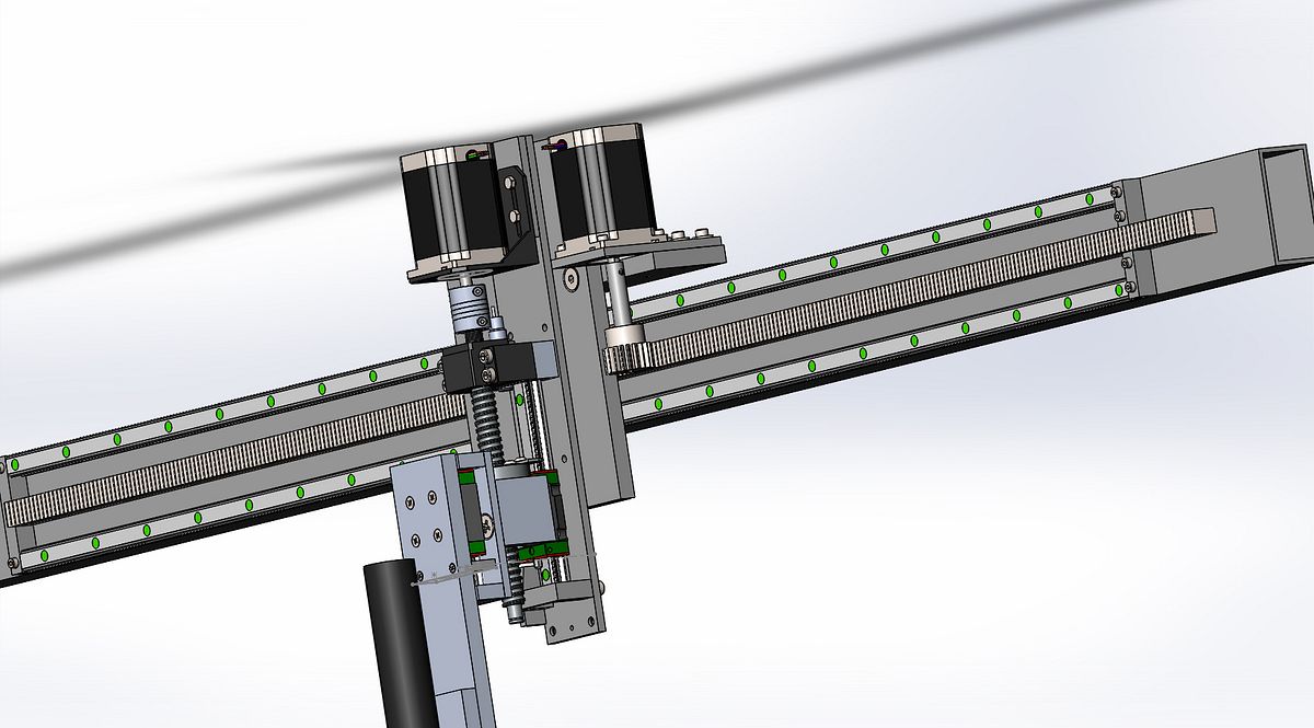
After hundreds of hours designing a machine, it is finally coming together. After machining 20 or so parts, finally, the Z axis is complete and I am sure it will work nicely.
Originally, I was going to make a ghetto build machine but since I got the idea, I've purchased an interest in a business that could use a plasma cutter so I am sparing no expense to do the job right. As I am surrounded by fabricators, the table will also be of commercial quality.
These are just quick pics taken with my phone, I will post up some better ones one day if I find the time to pohotograph it properly.
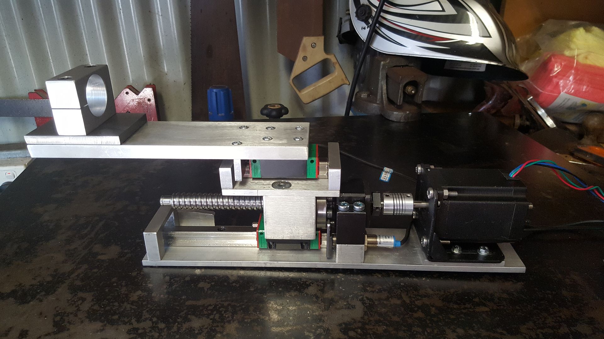
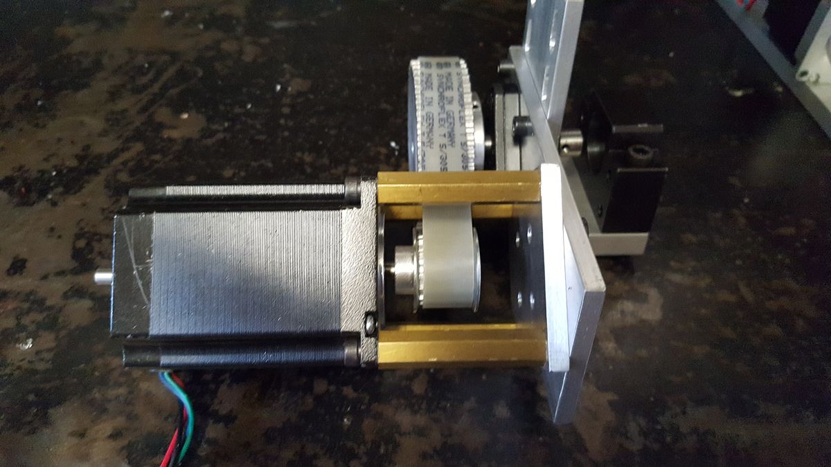
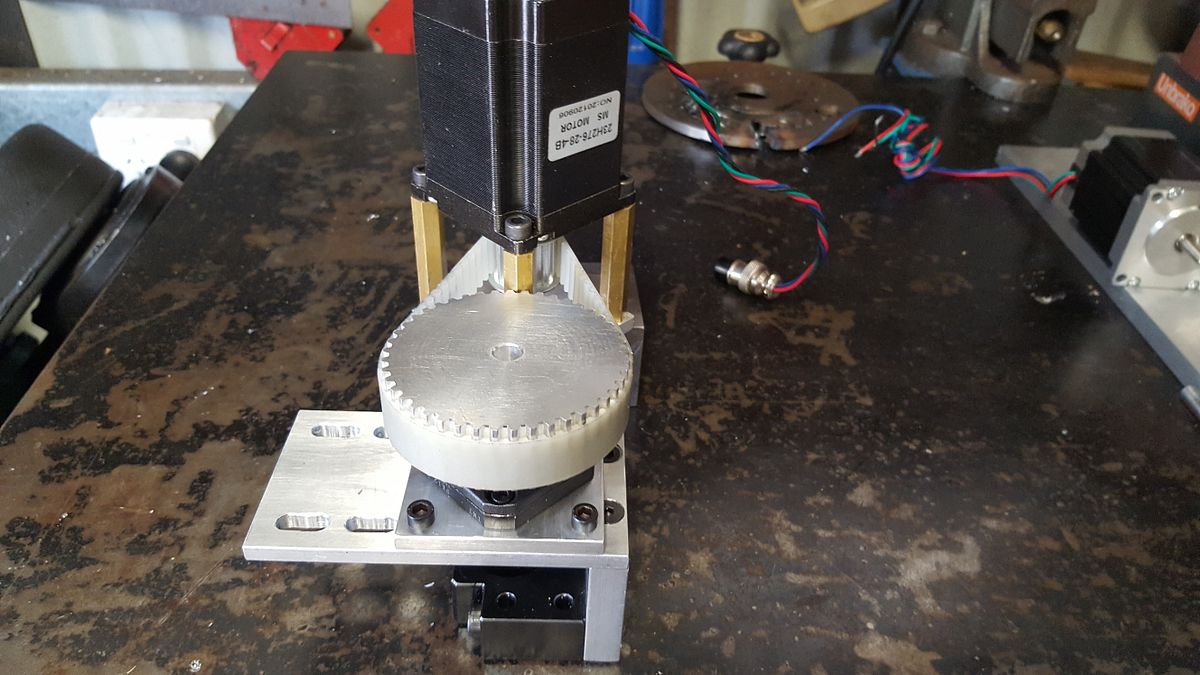
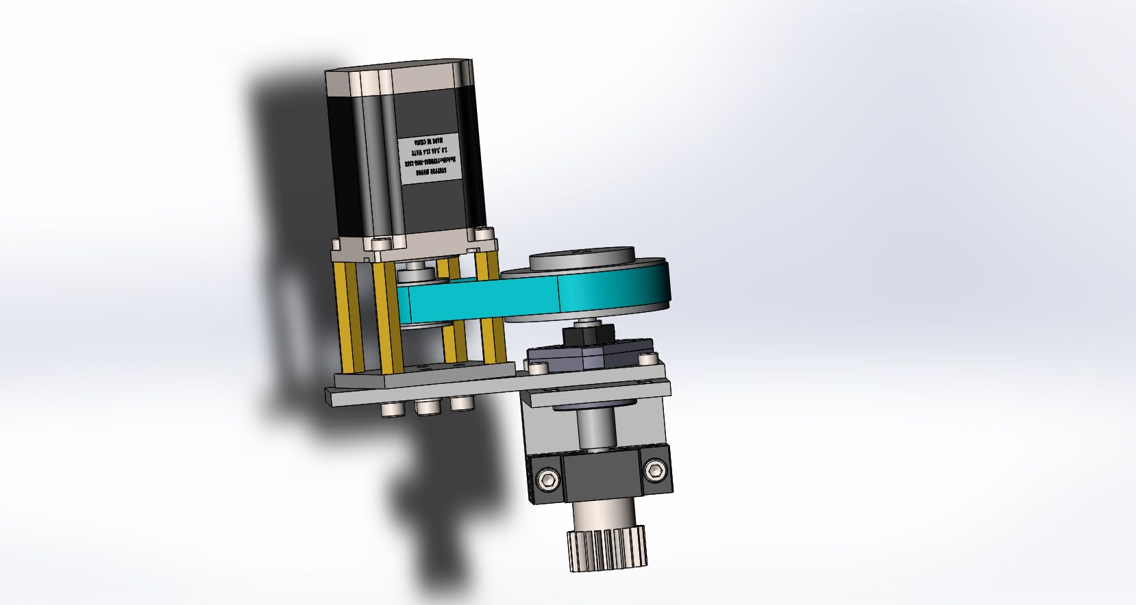
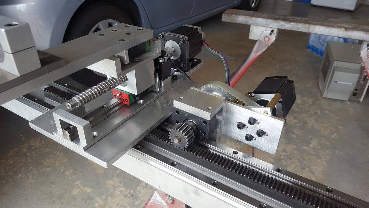
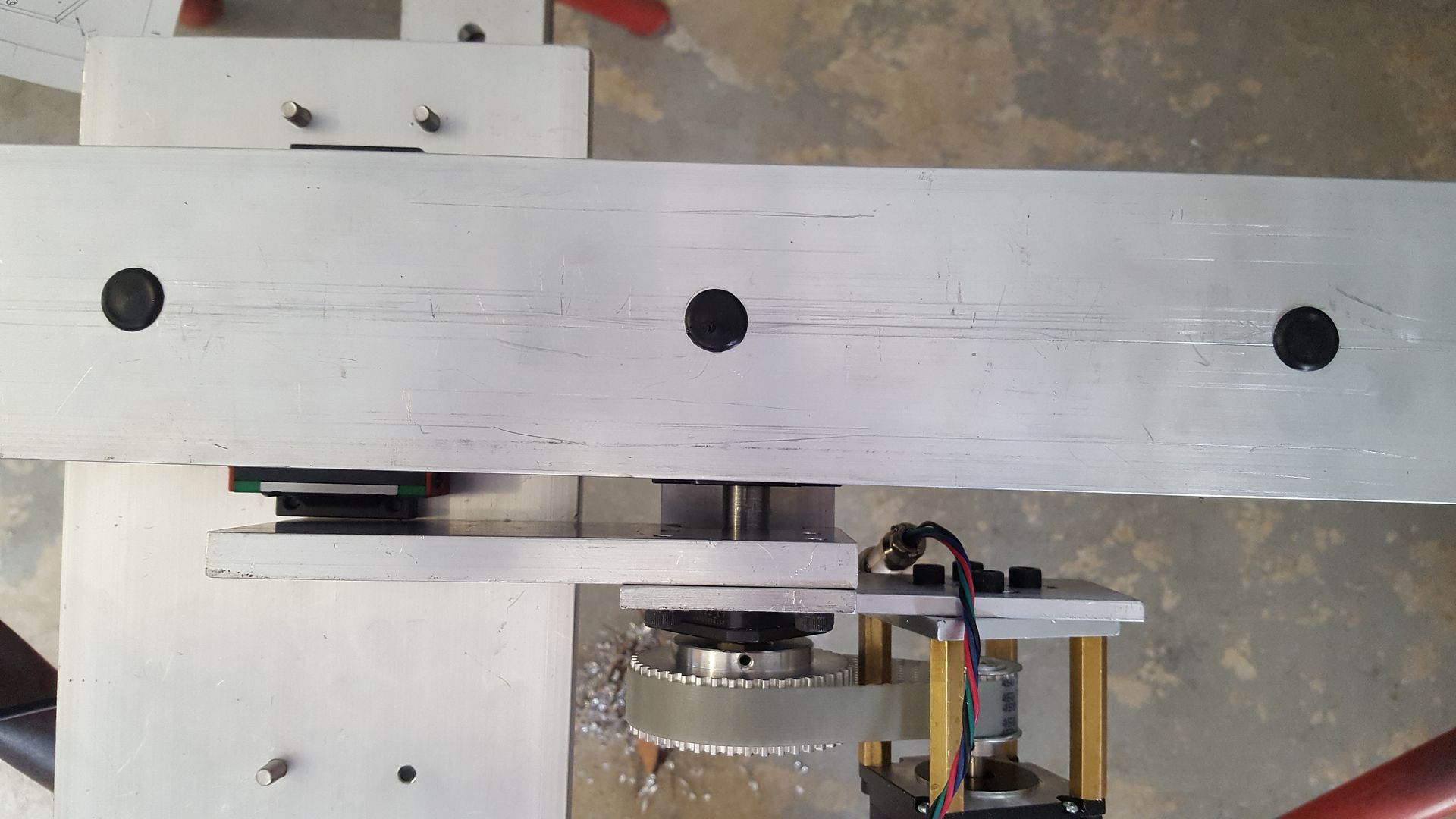
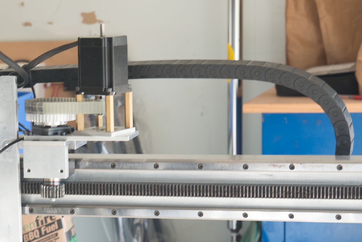
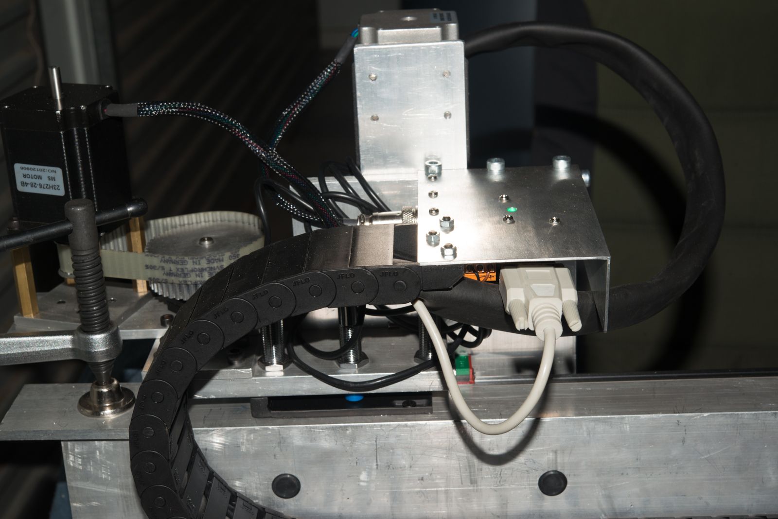
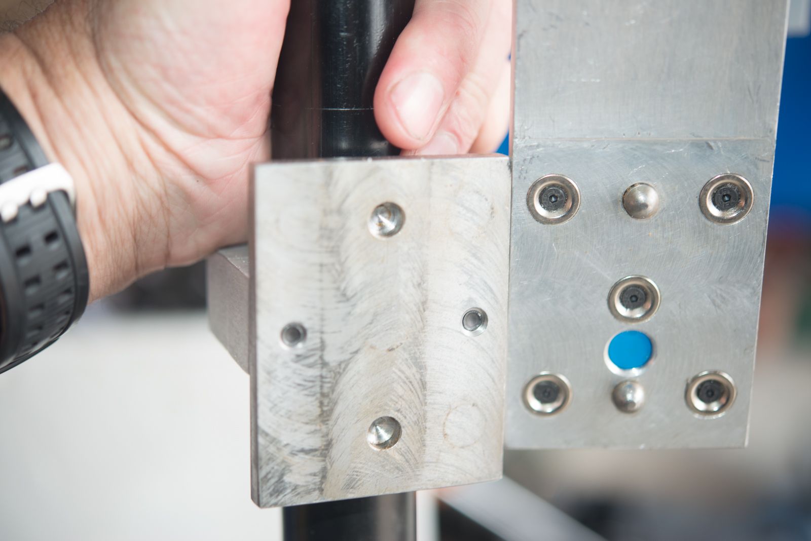
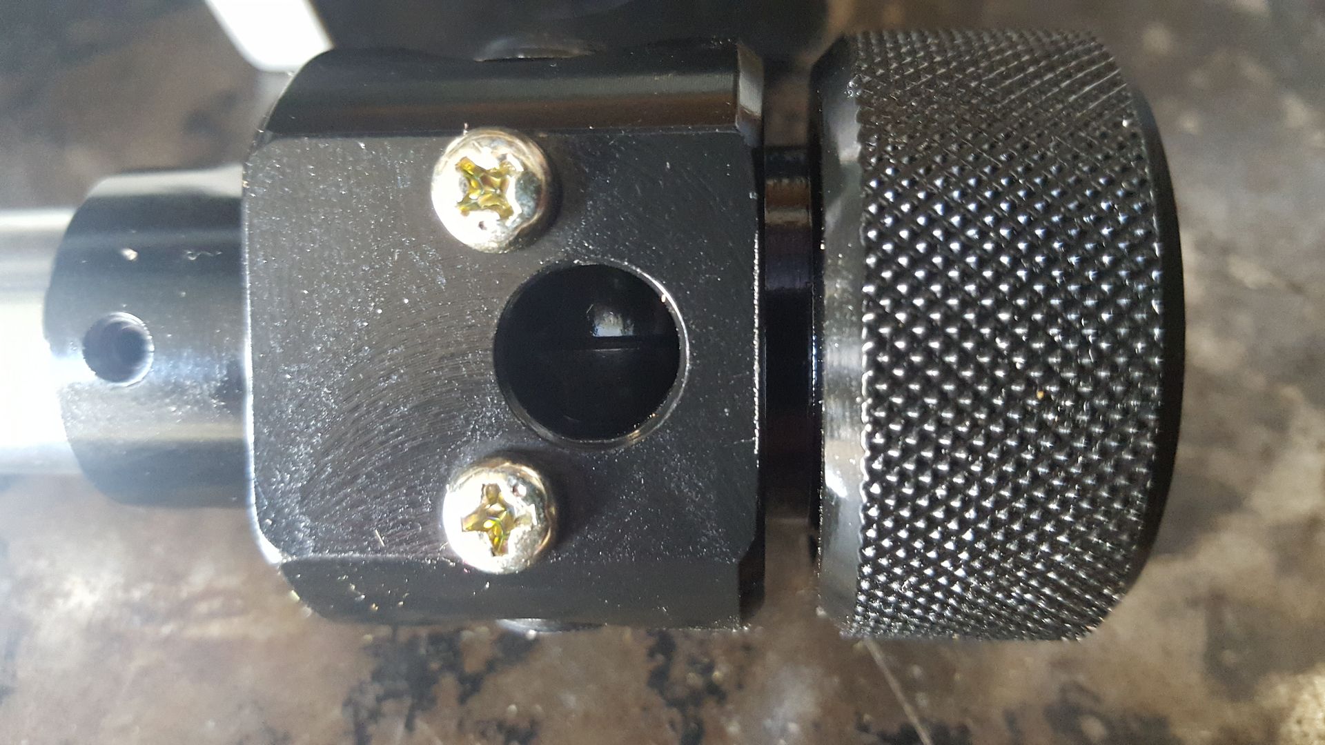
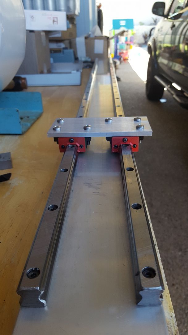
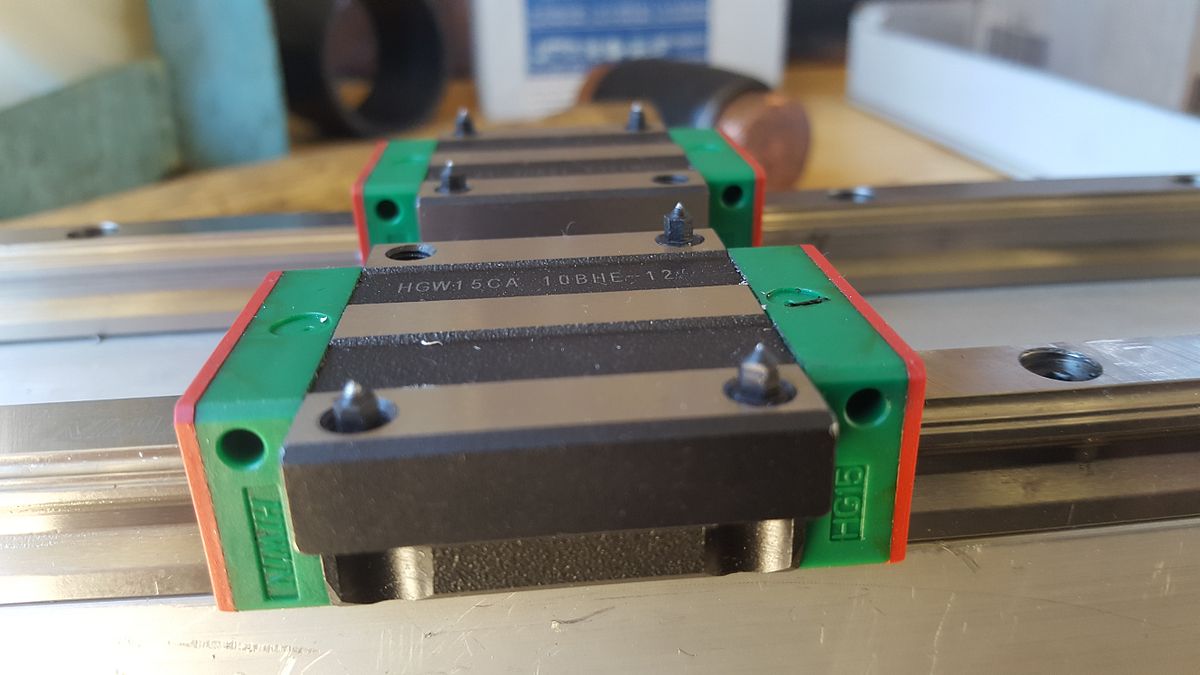
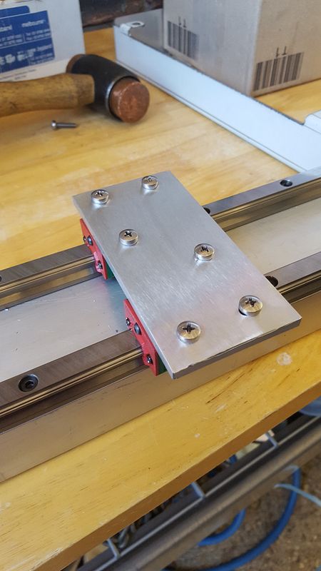
It has a 150mm ball screw which gives total travel of about 100mm. You can see that there are 2 linear rails. One is for the Z axis itself, and the other is a short floating section that senses the material.
Plasma is a bit different to other CNC machines as there are no cutting forces. Here is what happens at the start of a cut.
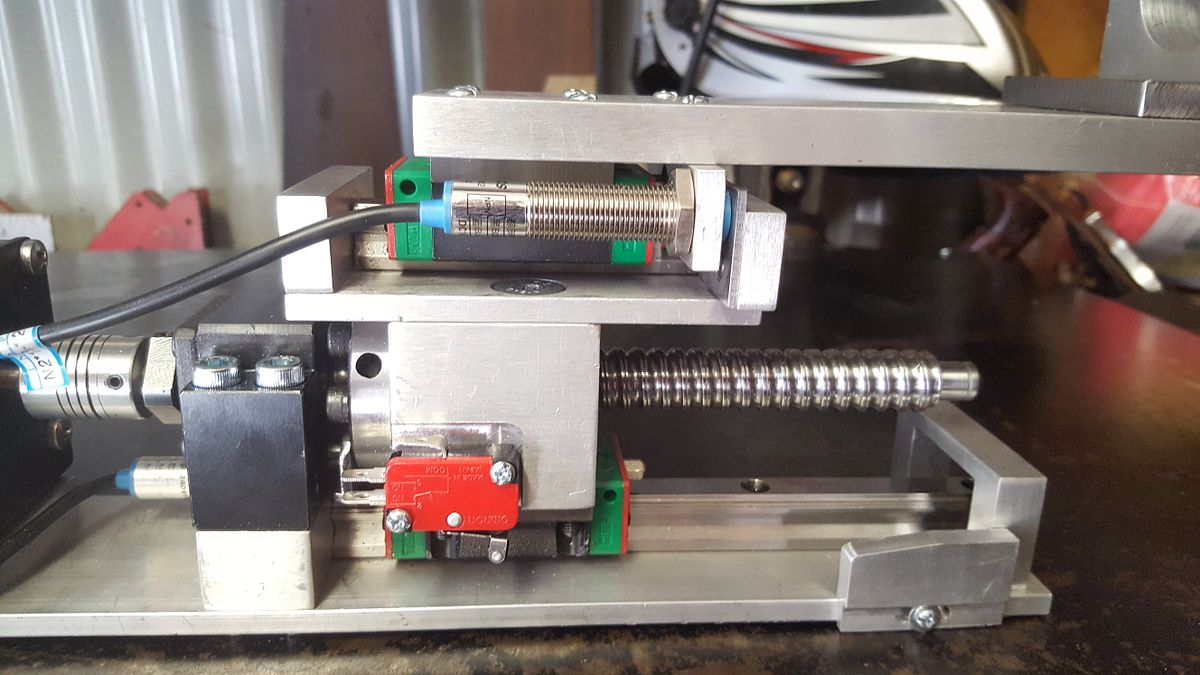
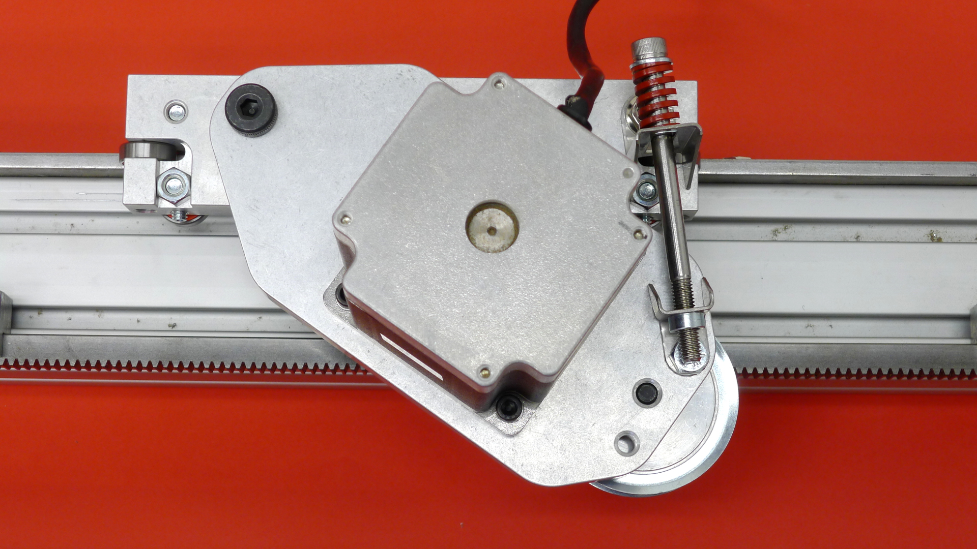
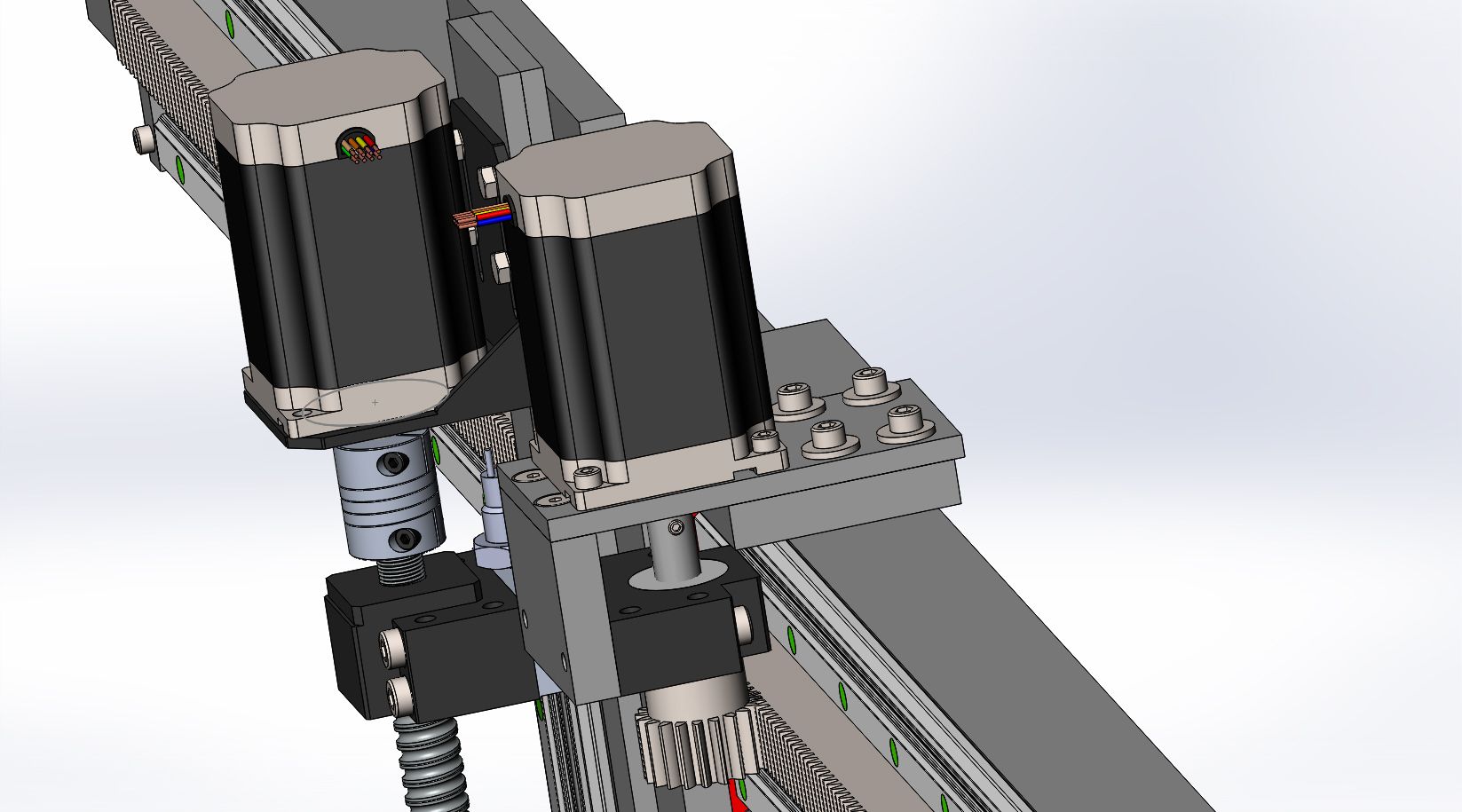
1. The torch rises until it trips the home sensor which you can see below the black bearing mount on the stepper side.
2. The torch hits the material and moves up along the floating rail. This trips the upper proximity sensor.
3. The torch height is adjusted for the switch hysterisis.
4. The torch raises to cutting height (around 250% above cutting height)
5. The controller fires the torch.
6. Once the Arc is established, the Plasma cutter sends an ARC OK signal back to the CNC controller
7. The torch is lowerd to the cutting height and off it goes.
8. The CNC controller monitors the arc voltage sent back though a voltage divider from the Plasma cutter as the voltage is a function of torch height.
9. The torch height is maintained constant based on this voltage as parts can tip up or warp while being cut.
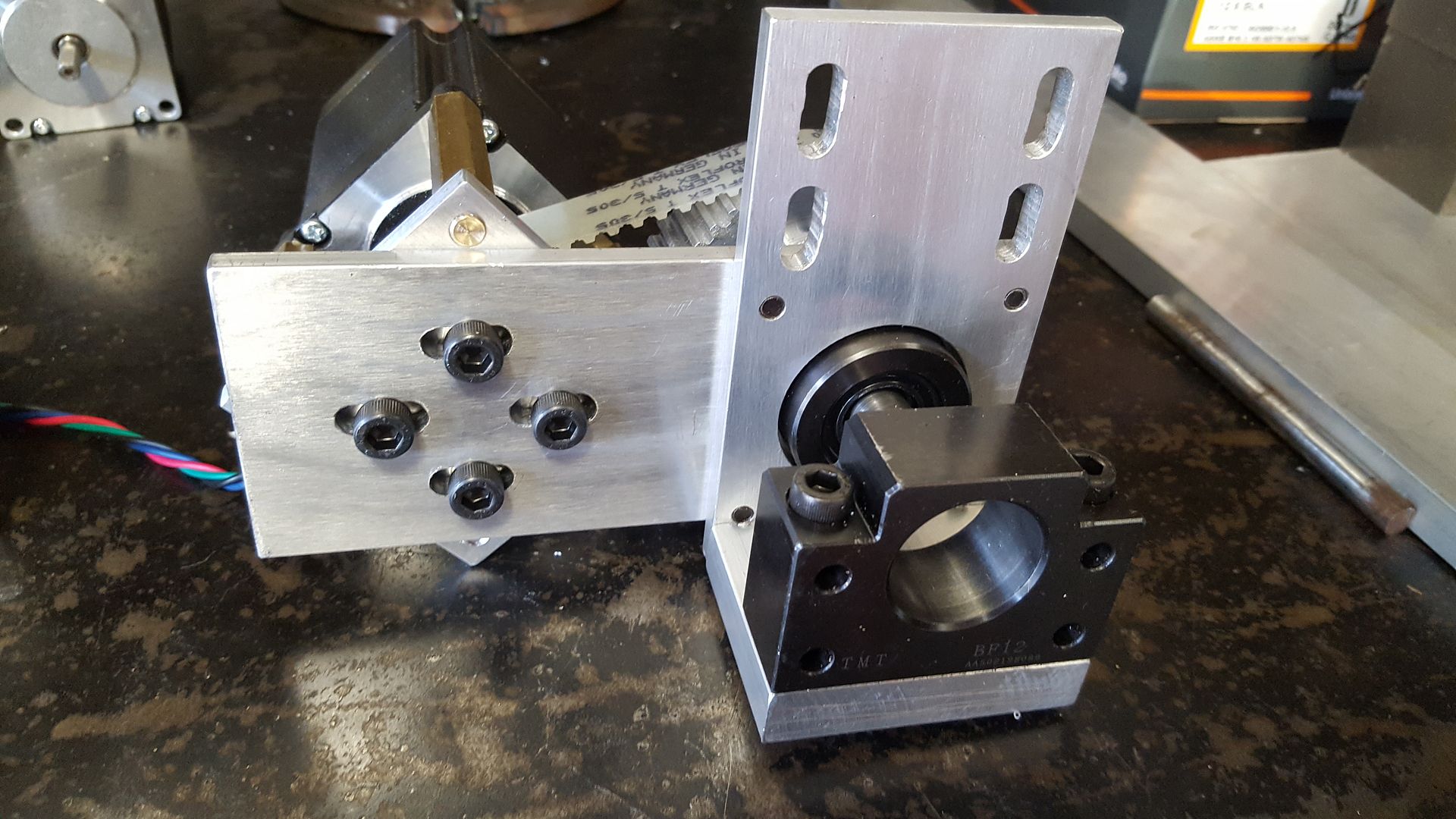
The red micro switch is a limit switch so the ballscrew does not fall apart. In theory, it should never be tripped as the material sensor should always be triggered before it.
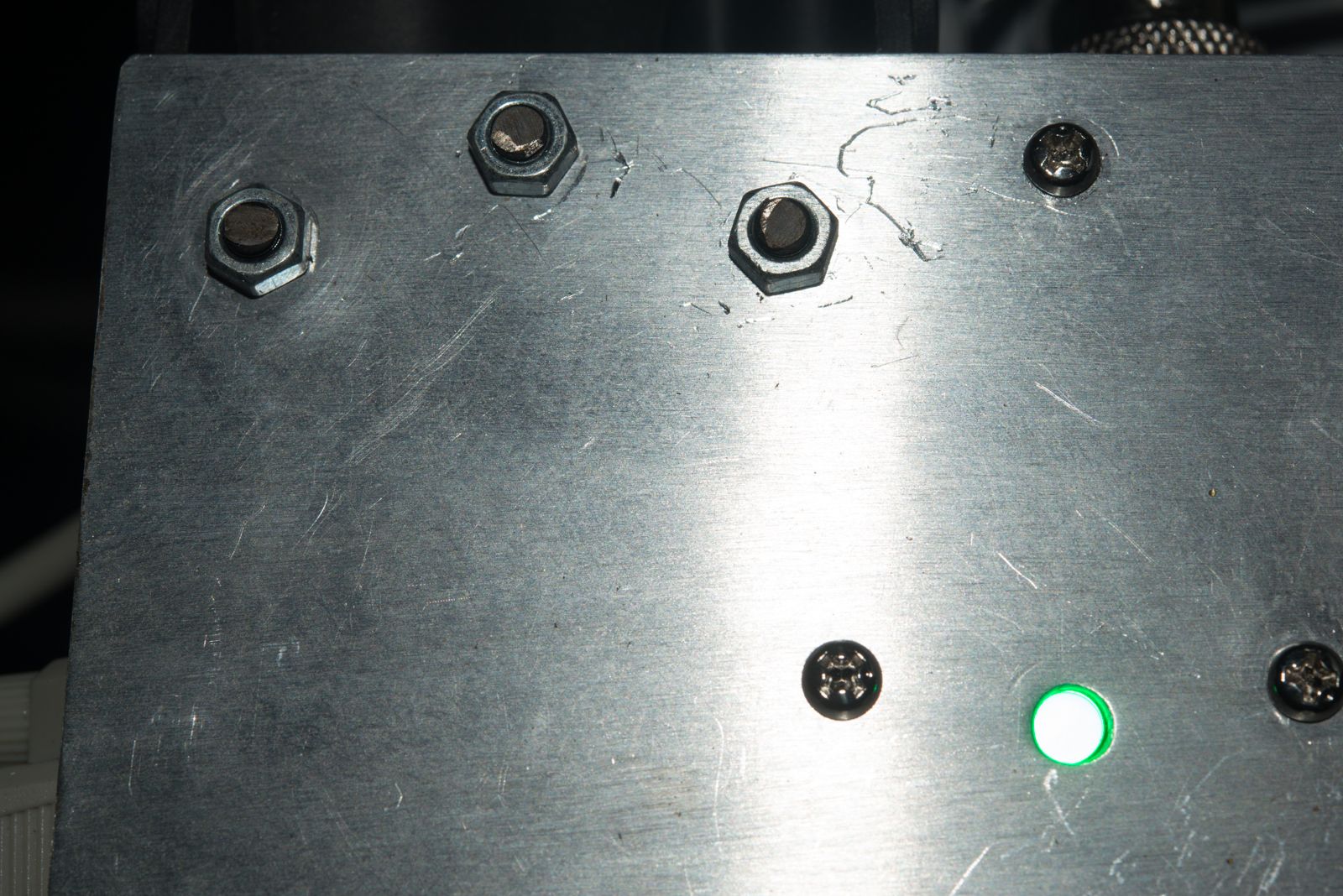
The other thing that could happen is the torch could hit something that could damage the machine. To protect against this, I've added a breakaway magnetic Torch mount.

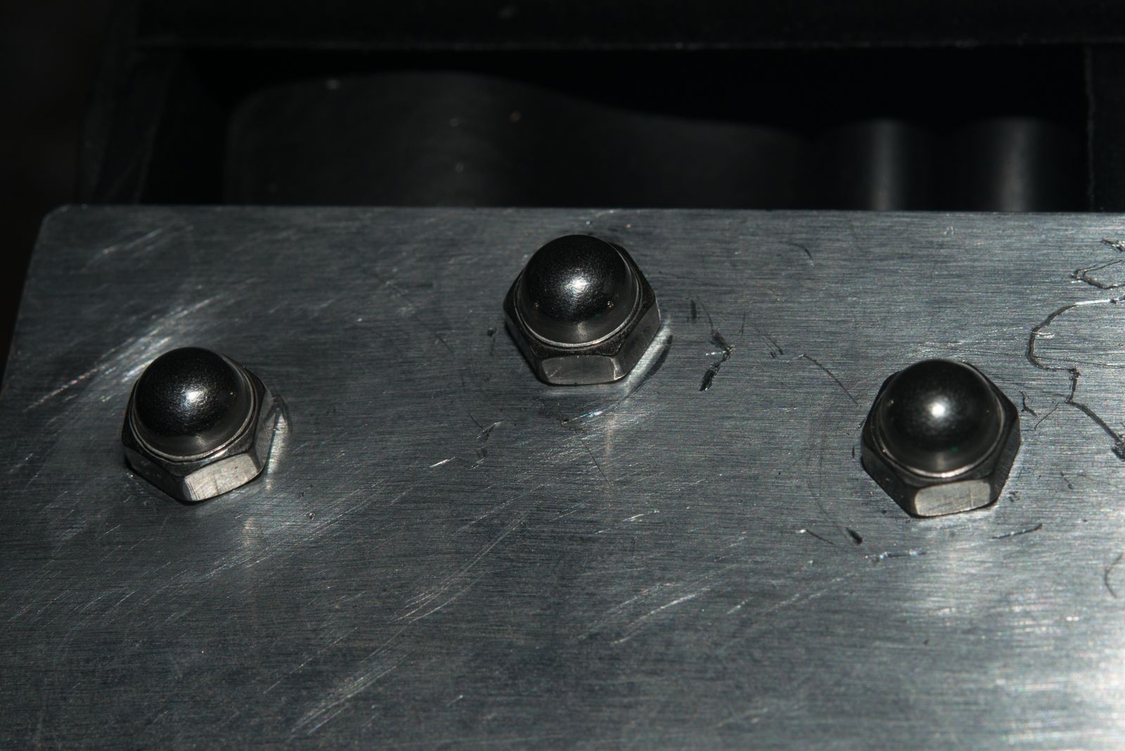
This has 5 x 12.5mm dia magnets that are 3.5mm thick. These have been pressed into holes cut with a 12.5mm endmill so they are just proud of the mounting surface. They are secured by 3mm countersunk screws. The locating pins have been machined using my boring head ball turner documented elsewhere on this forum which are a press fit (helped with some retaining compound. This is the second iteration of the magnetic breakaway mount. Initially I wanted to use a pair of North and South oriented magnets so that one magnet was sitting below the surface and the other located into the recess. I found the magnets were not dimensionally accurate and also turned out to be a press fit. Breaking an M4 tap on th elast hole was the final straw but I decided the part needed a total redesign and went with a steel plate located by the pins.
If the torch ever falls off, it makes sens to stop the machine immediately so I've drilled and tapped the back side for another proximity sensor which will return an e-stop if it ever triggers.
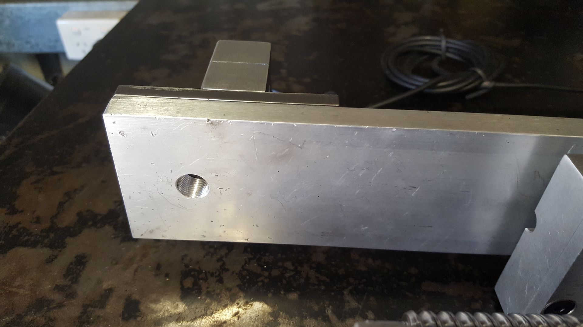
The reason why the torch mount is a lot lower than the carriage is that I hope to be able to build a cover for the axis to keep out metal dust.
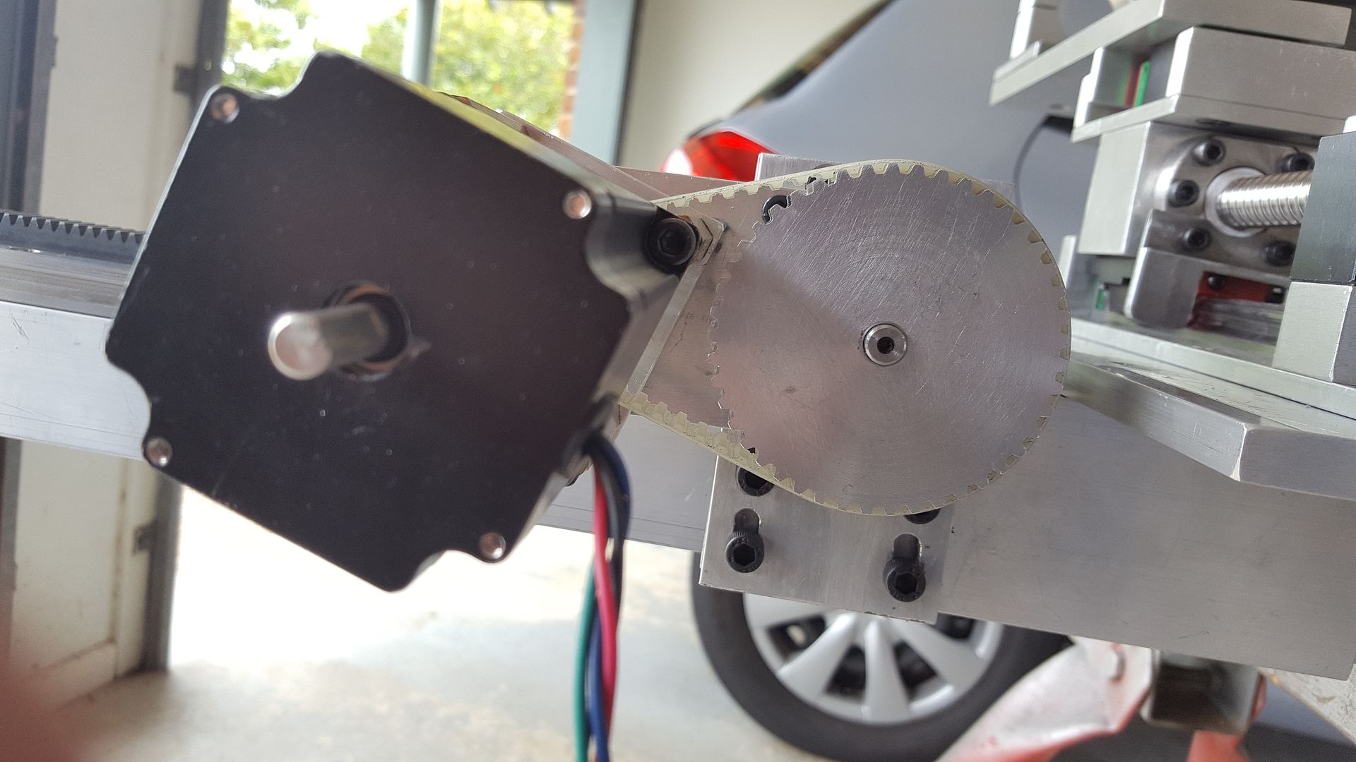
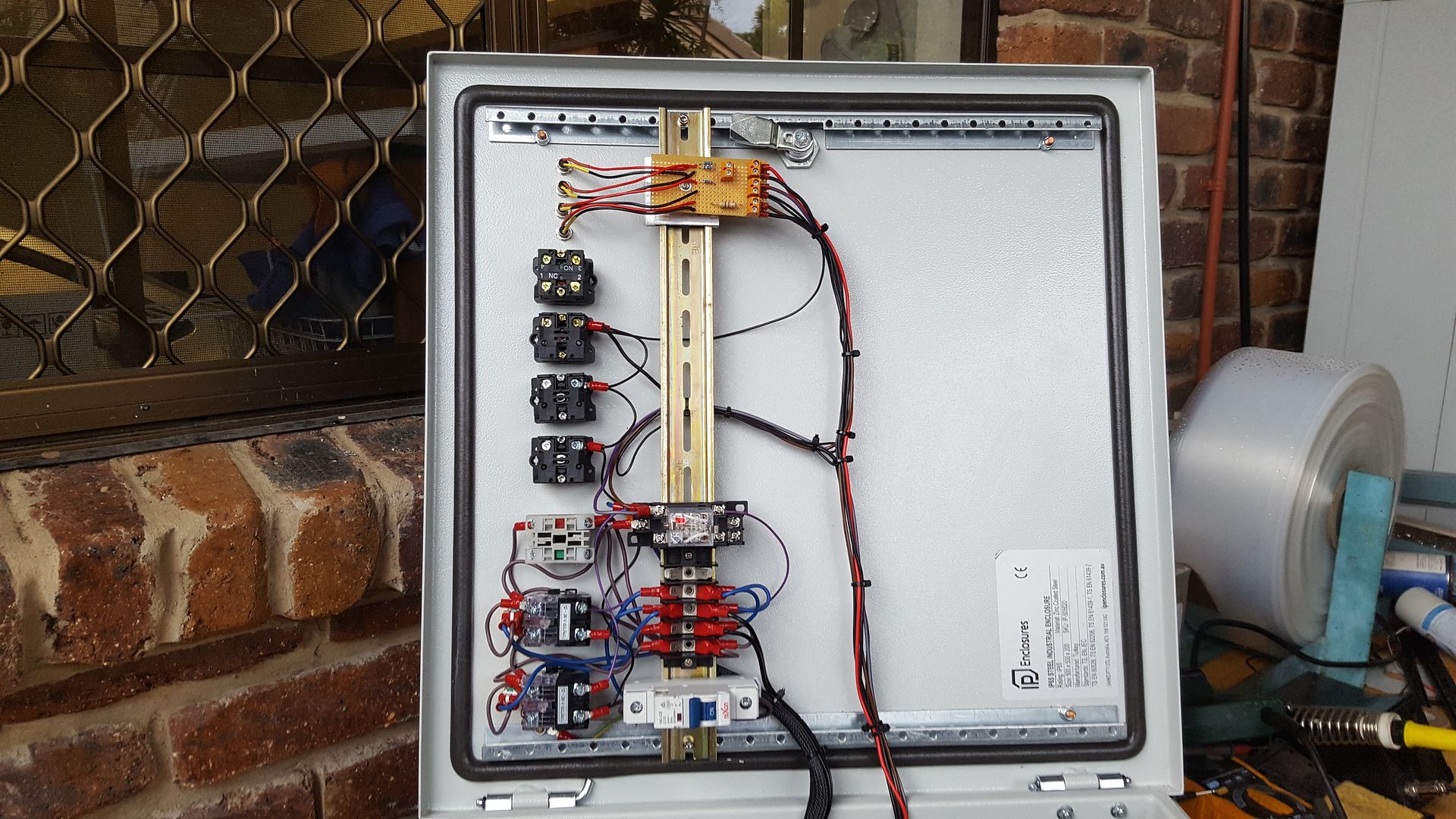
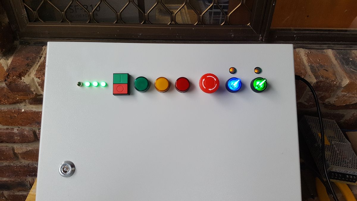
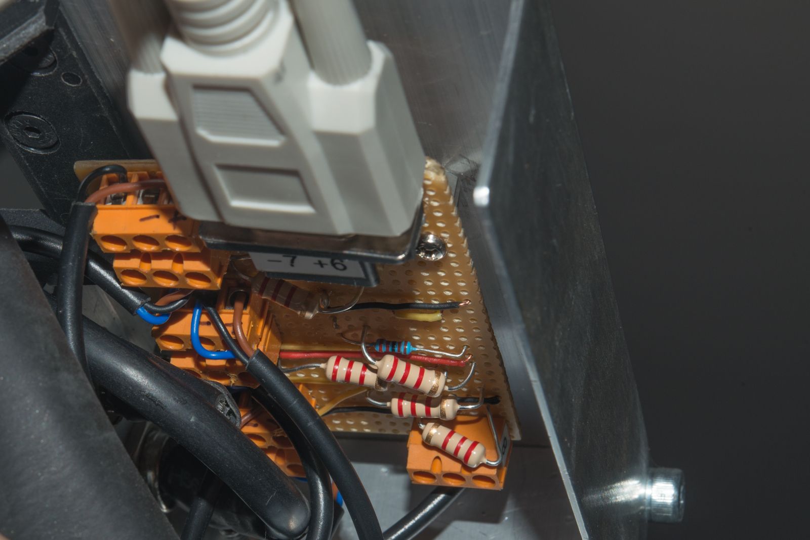
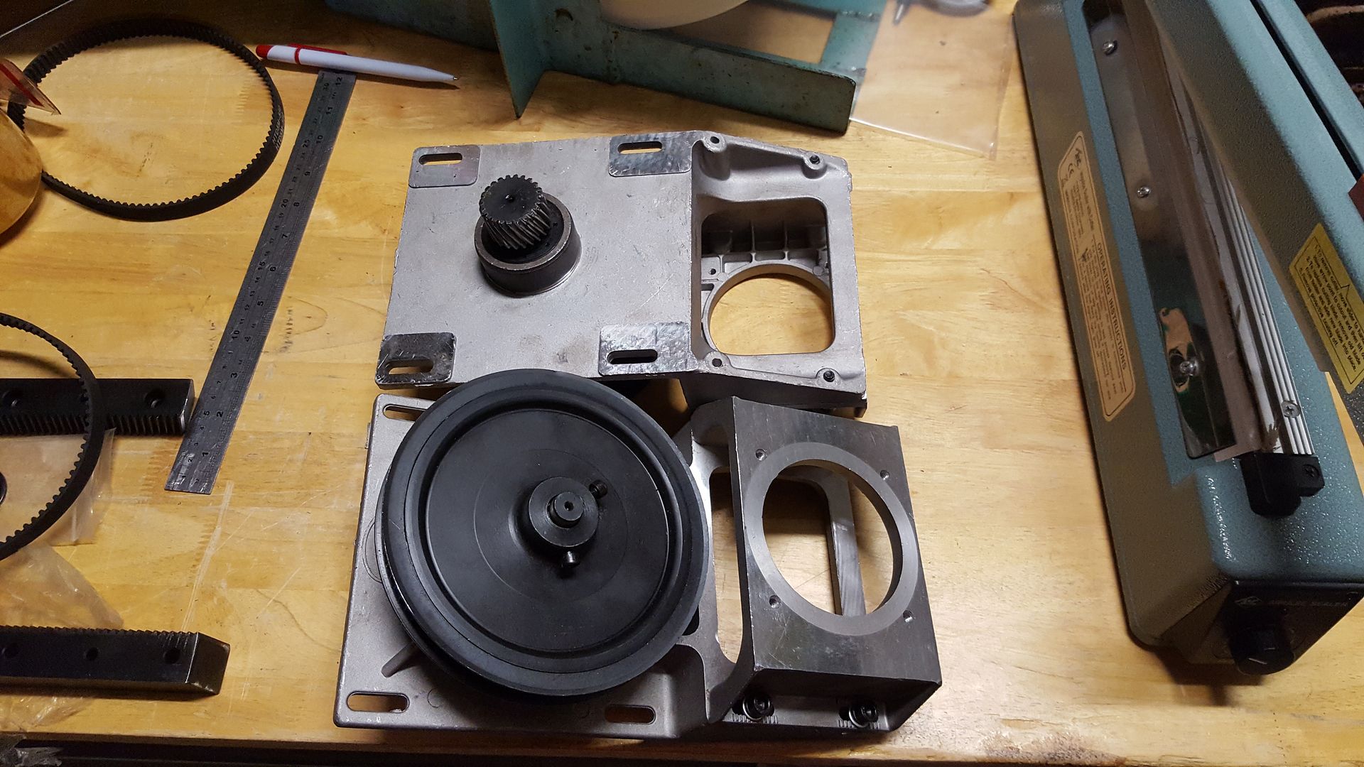
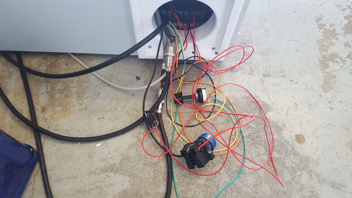
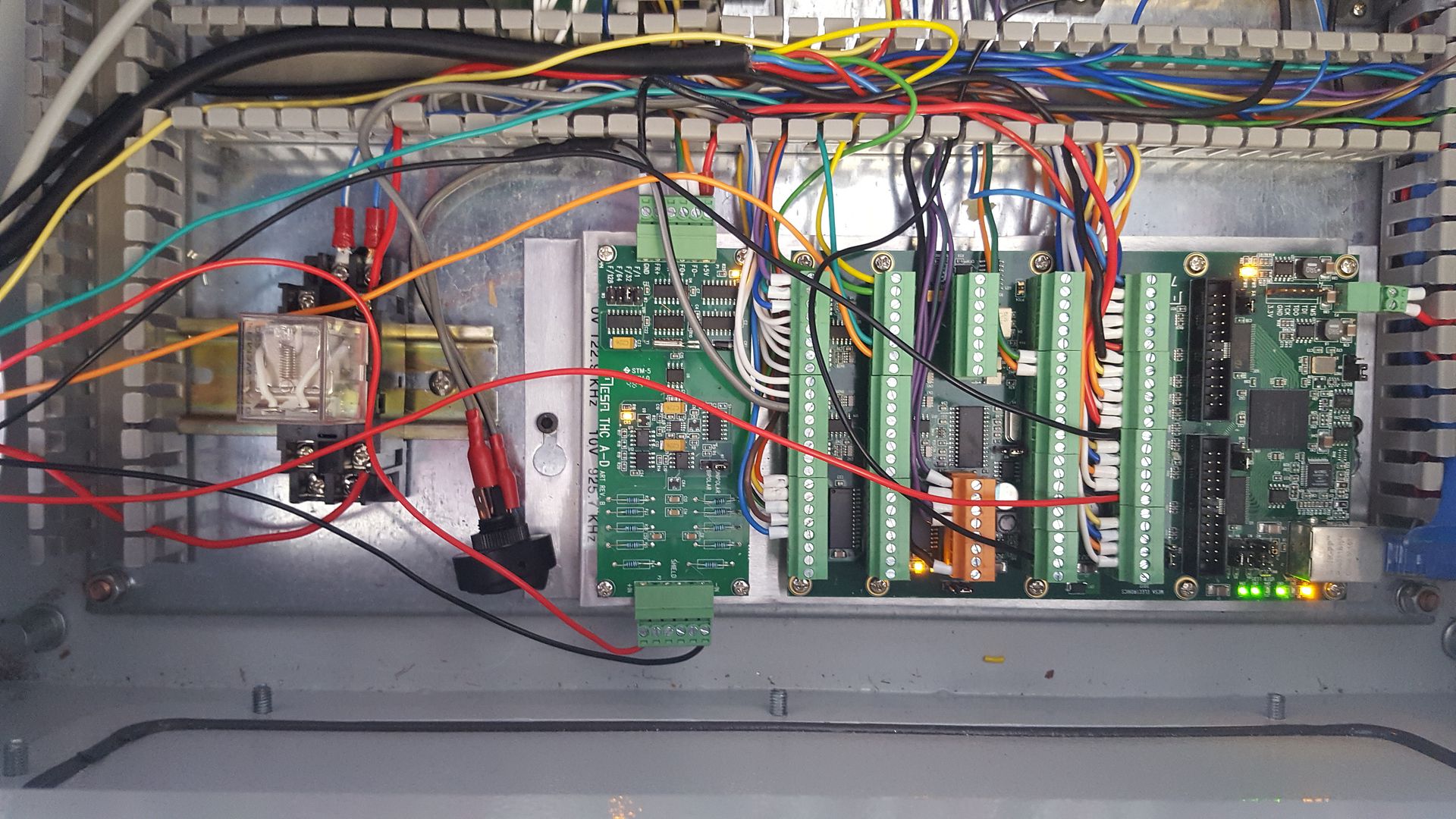
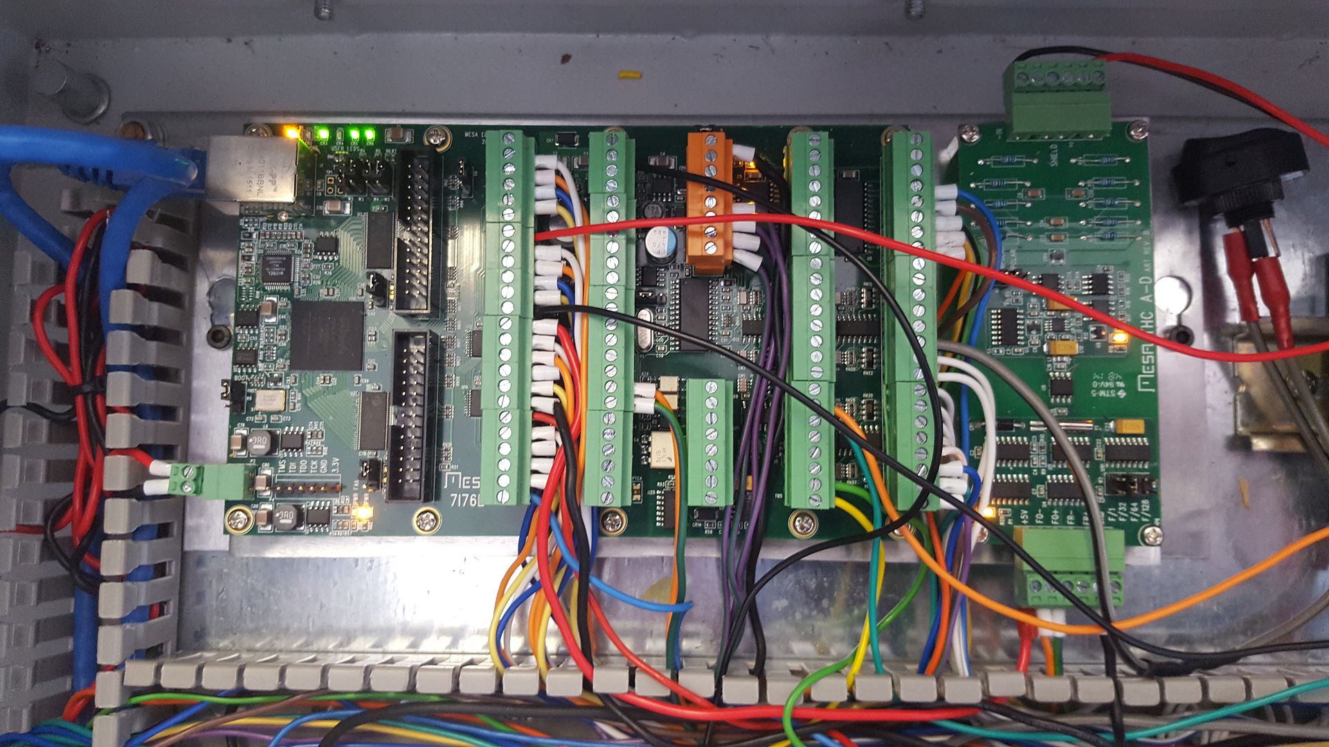
This machine will be controlled by LinuxCNC and I have purchased an Ethernet Mesanet 7i67E interface card and the matching MESA THCUD torch height controller daughter board. Unfortunately, the Mesa board is significantly larger than the Breakout board in the yellow case, so everything needs to be stripped and remounted into a 500mm x 500mm enclosure I've purchased.
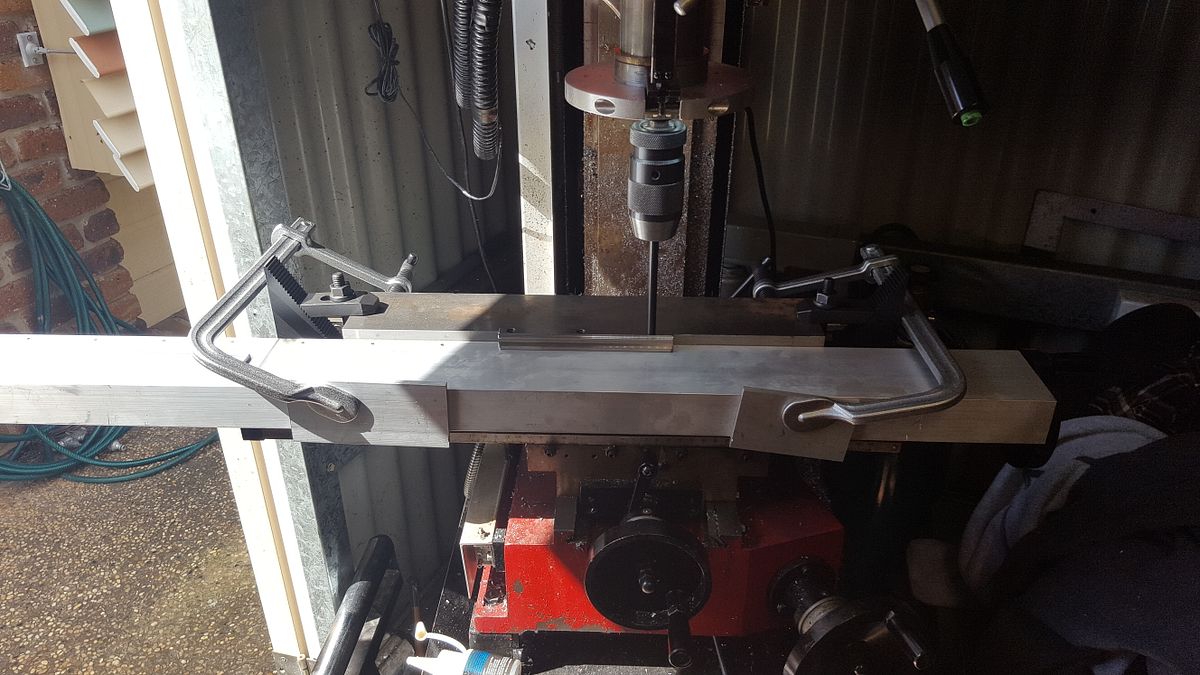
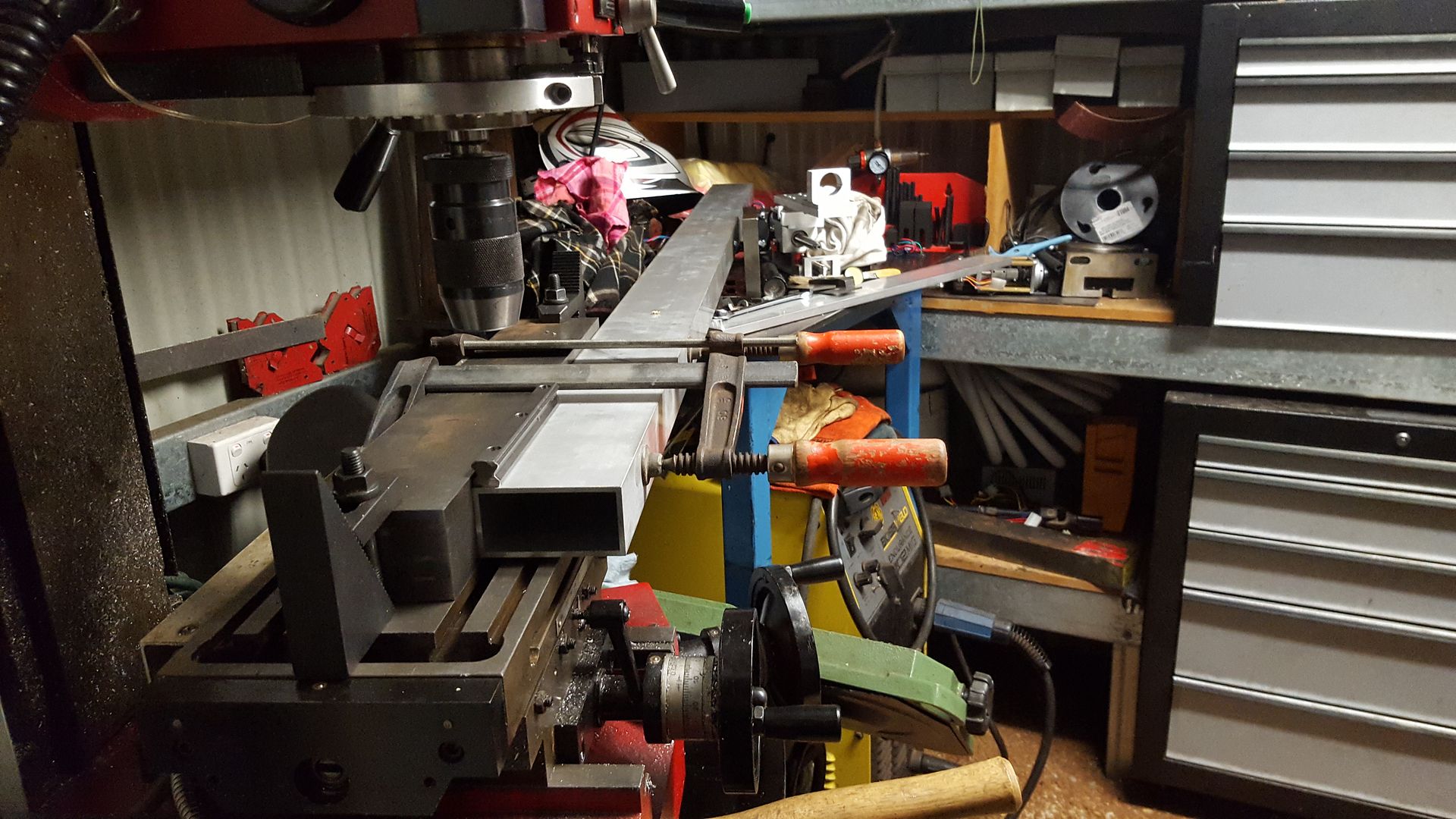
Today, I managed to drill and tap 44 x 4 mm holes into a piece of Aluminium RHS on my little SX3 mill. This proved quite a mission as the X axis handle sits proud of the mounting table so the RHS had to hang off the table to get about 2mm clearance from the handle.
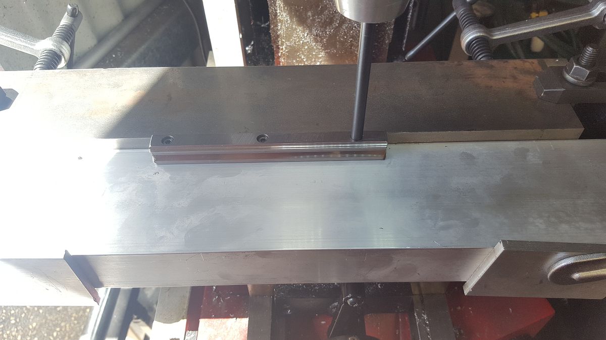
Its a bit hard to see but there is a length of 75mm x 50mm steel mounted to the table to act as a fence so I could slide the material along. I used a short piece of scrap linear guide when I had to reposition the material (table travel limited me to 7 holes at a time and there are 22 on each rail.). I've screwed this scrap down with 2 screws and located the undrilled hole with a close fitting punch. This worked pretty well but on the first side, I started at one end and was out a bit by the time I got to the other. On the second side, I started in the middle to halve any error.
The problem with this setup is that the holes have been referenced on 2 different sides so I don't really know exactly how far apart the rails are. That won't be hard to sort out.
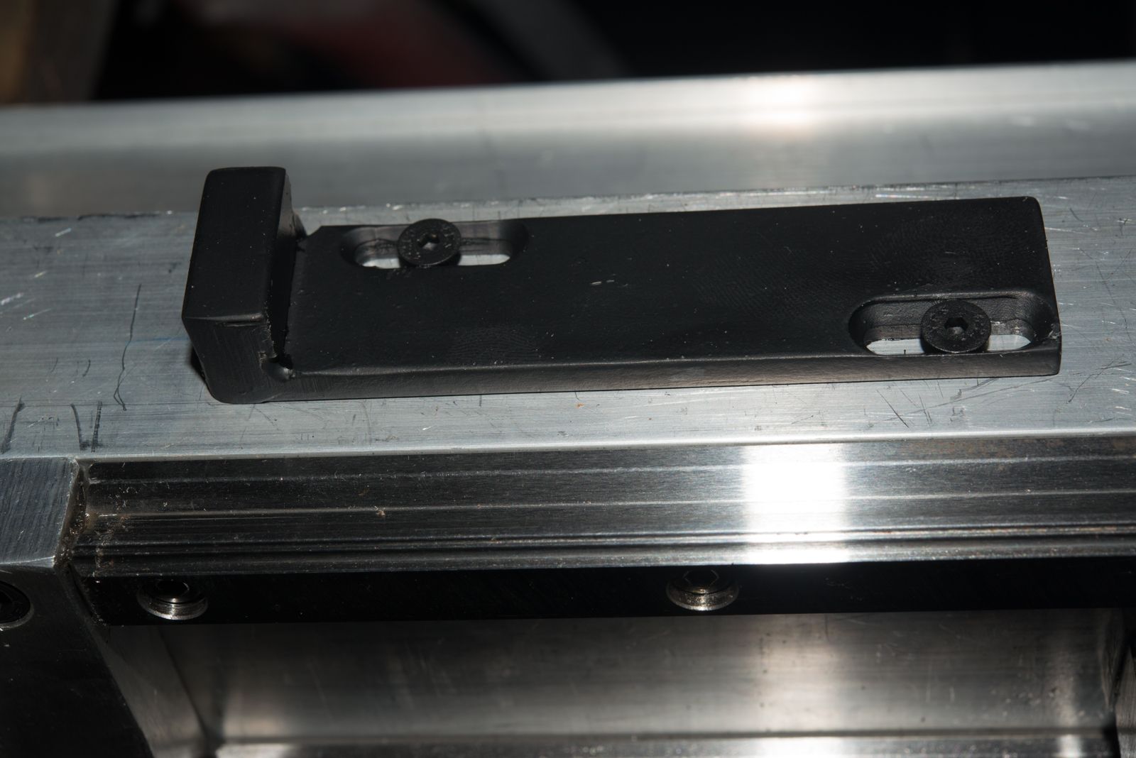
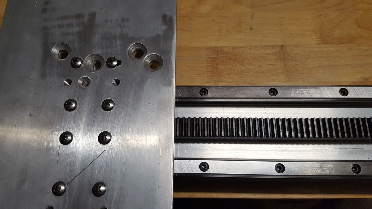
I clamped one rail to the back fence when mounting it. The steel fence is dimensionally accurate, but I've forgotten the accuracy spec. The second rail is still loose and will be tightened up once I get a carriage mounted up.
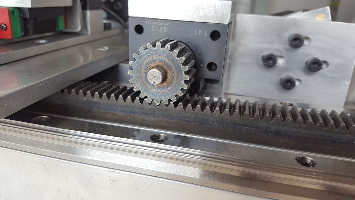
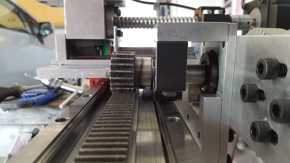
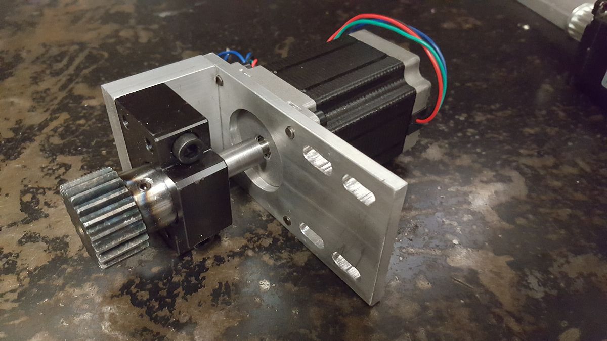
I'll try and post up a few more photos tomorrow as I hope to get the Y axis close to finished. The plan is to have 2 linear rails on the front face of the RHS and a gear rack for the rack and pinion drive mounted underneath to shield it from dust as much as it can be. This is going to be a bit of a pain as its designed to be mounted from the rear into M6 holes in the rear of the rack. I'm going to have to drill access holes on the top surface to fix the rack. I'm glad thes holes are much further apart than the 60mm on the linear rails!
I got very disollusioned becasue my cheap plasma cutter died and the parallel port Break Out Board refused to talk to the PC.
So it sat on my desk for the next 10 months or so until one day I remembered how much time and effort went into it so I decided to kick start the project again. So in June, I purchased a 50 amp Everlast Plasma cutter with CNC interface and a CNC torch for it.
After hundreds of hours designing a machine, it is finally coming together. After machining 20 or so parts, finally, the Z axis is complete and I am sure it will work nicely.
Originally, I was going to make a ghetto build machine but since I got the idea, I've purchased an interest in a business that could use a plasma cutter so I am sparing no expense to do the job right. As I am surrounded by fabricators, the table will also be of commercial quality.
These are just quick pics taken with my phone, I will post up some better ones one day if I find the time to pohotograph it properly.
It has a 150mm ball screw which gives total travel of about 100mm. You can see that there are 2 linear rails. One is for the Z axis itself, and the other is a short floating section that senses the material.
Plasma is a bit different to other CNC machines as there are no cutting forces. Here is what happens at the start of a cut.
1. The torch rises until it trips the home sensor which you can see below the black bearing mount on the stepper side.
2. The torch hits the material and moves up along the floating rail. This trips the upper proximity sensor.
3. The torch height is adjusted for the switch hysterisis.
4. The torch raises to cutting height (around 250% above cutting height)
5. The controller fires the torch.
6. Once the Arc is established, the Plasma cutter sends an ARC OK signal back to the CNC controller
7. The torch is lowerd to the cutting height and off it goes.
8. The CNC controller monitors the arc voltage sent back though a voltage divider from the Plasma cutter as the voltage is a function of torch height.
9. The torch height is maintained constant based on this voltage as parts can tip up or warp while being cut.
The red micro switch is a limit switch so the ballscrew does not fall apart. In theory, it should never be tripped as the material sensor should always be triggered before it.
The other thing that could happen is the torch could hit something that could damage the machine. To protect against this, I've added a breakaway magnetic Torch mount.
This has 5 x 12.5mm dia magnets that are 3.5mm thick. These have been pressed into holes cut with a 12.5mm endmill so they are just proud of the mounting surface. They are secured by 3mm countersunk screws. The locating pins have been machined using my boring head ball turner documented elsewhere on this forum which are a press fit (helped with some retaining compound. This is the second iteration of the magnetic breakaway mount. Initially I wanted to use a pair of North and South oriented magnets so that one magnet was sitting below the surface and the other located into the recess. I found the magnets were not dimensionally accurate and also turned out to be a press fit. Breaking an M4 tap on th elast hole was the final straw but I decided the part needed a total redesign and went with a steel plate located by the pins.
If the torch ever falls off, it makes sens to stop the machine immediately so I've drilled and tapped the back side for another proximity sensor which will return an e-stop if it ever triggers.
The reason why the torch mount is a lot lower than the carriage is that I hope to be able to build a cover for the axis to keep out metal dust.
This machine will be controlled by LinuxCNC and I have purchased an Ethernet Mesanet 7i67E interface card and the matching MESA THCUD torch height controller daughter board. Unfortunately, the Mesa board is significantly larger than the Breakout board in the yellow case, so everything needs to be stripped and remounted into a 500mm x 500mm enclosure I've purchased.
Today, I managed to drill and tap 44 x 4 mm holes into a piece of Aluminium RHS on my little SX3 mill. This proved quite a mission as the X axis handle sits proud of the mounting table so the RHS had to hang off the table to get about 2mm clearance from the handle.
Its a bit hard to see but there is a length of 75mm x 50mm steel mounted to the table to act as a fence so I could slide the material along. I used a short piece of scrap linear guide when I had to reposition the material (table travel limited me to 7 holes at a time and there are 22 on each rail.). I've screwed this scrap down with 2 screws and located the undrilled hole with a close fitting punch. This worked pretty well but on the first side, I started at one end and was out a bit by the time I got to the other. On the second side, I started in the middle to halve any error.
The problem with this setup is that the holes have been referenced on 2 different sides so I don't really know exactly how far apart the rails are. That won't be hard to sort out.
I clamped one rail to the back fence when mounting it. The steel fence is dimensionally accurate, but I've forgotten the accuracy spec. The second rail is still loose and will be tightened up once I get a carriage mounted up.
I'll try and post up a few more photos tomorrow as I hope to get the Y axis close to finished. The plan is to have 2 linear rails on the front face of the RHS and a gear rack for the rack and pinion drive mounted underneath to shield it from dust as much as it can be. This is going to be a bit of a pain as its designed to be mounted from the rear into M6 holes in the rear of the rack. I'm going to have to drill access holes on the top surface to fix the rack. I'm glad thes holes are much further apart than the 60mm on the linear rails!


![DreamPlan Home Design and Landscaping Software Free for Windows [PC Download]](https://m.media-amazon.com/images/I/51kvZH2dVLL._SL500_.jpg)


![MeshMagic 3D Free 3D Modeling Software [Download]](https://m.media-amazon.com/images/I/B1U+p8ewjGS._SL500_.png)


")