


Hi all,
I thought it was time I post up some info about my latest project!
A bit about me and the project.
I am a design engineer for a well known vacuum cleaner company based in the UK. I have always loved building and making model and using engineering machines to make precise parts
So recently I have wanted a project that is a bit more involved than buying a plastic kit from the shop to assemble, this combined with my desire to get a classic American V8 muscle car (but no money) has led me down this path! With no engineering machines at home to use and not currently having the skills to machine this all from billet aluminium I have used my knowledge of modern CAD and 3D printing.
This is a scale V8 engine that I have modeled it up on CAD the idea is that it can be compressed air powered. I have had all the parts 3D printed from nylon and I am now in the assembly/tinkering phase to get it working
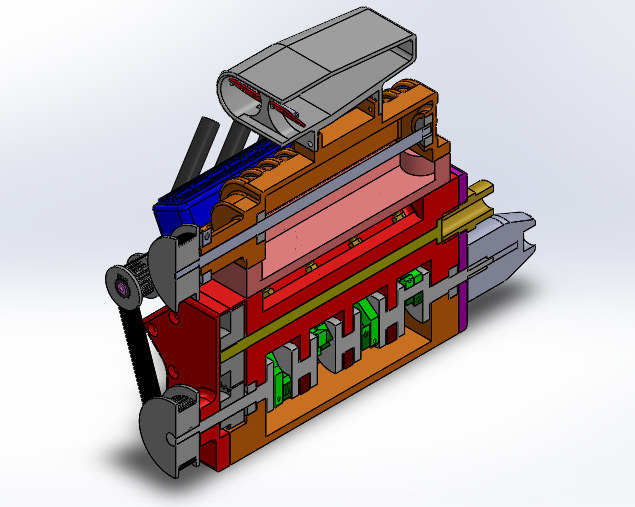
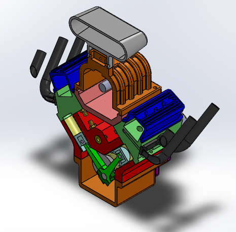
CAD screenshot
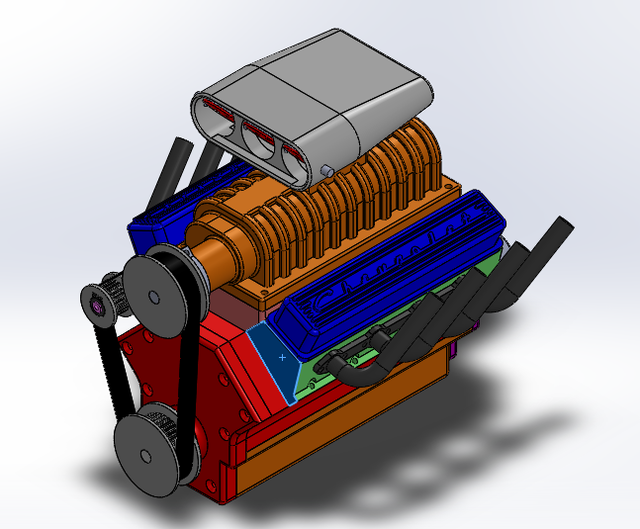
The supercharger/blower is all for show, no go hopefully the engine will be powerful enough to turn the supercharger. But I couldn't design the V8 without a supercharger
My idea was to get the engine running of compressed air to prove it works, If I can't get it running I will at least paint it up and have a nice display piece!
I thought I would post it up here in its current state so I can get feedback and advice from all you knowledgeable people
More pictures to come and the progress so far
A big thanks to Chuck Fellows, Steve Huck and other members who have helped me with ideas with their fantastic design and skills.
Hope you like it
Loz
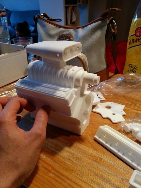
Arrival day of the printed parts :whoohoo: it took 3 weeks of waiting!
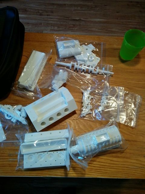
1st main part assembly
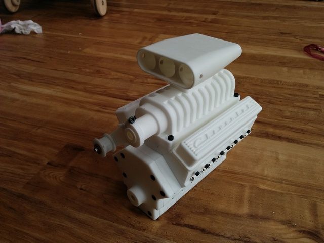
all holes drilled out and tapped
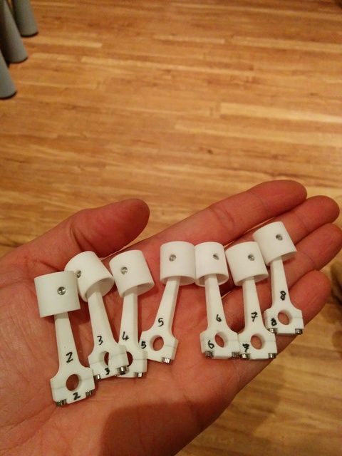
pistons & con rods assembled
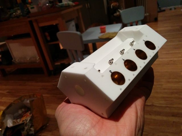
valve liners pressed in
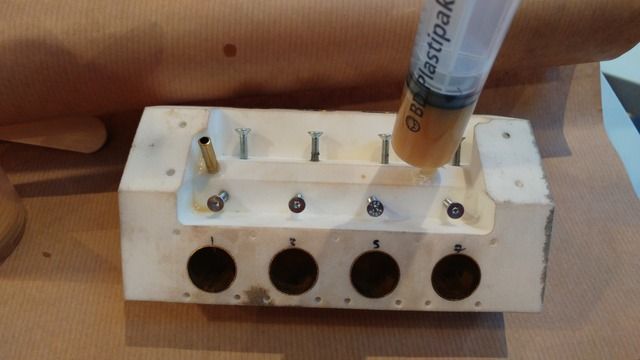
all was going well until i slipped while reaming out the rotary valve which put it off center :Mad: so i decided to drill the valve out larger and cast in a brass tube of the correct dimensions using a 2-part polyurethane
so this is where i am currently, the timing gears from the crank to rotary valve are too tight so awaiting 2 new slightly smaller gears to try out otherwise i may go for a belt driven timing connection. Hopefully the rotary valve will work in the new brass tube but it might be too small diameter and leak so i think i need to get back on the lathe at work and turn a new one up
Had a bit more time today to check over bits, the air valve is too small so i need to order new material and turn up a new one when it arrives. in the mean time i checked to see if the pistons move
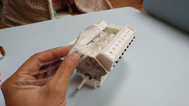
each of the silicone tubes connects to the valve in the head an to the pistons, i went through the firing sequece blasting in compressed air and each one moved perfectly;D;D so now i know that bit works its all about the valve now
I thought it was time I post up some info about my latest project!
A bit about me and the project.
I am a design engineer for a well known vacuum cleaner company based in the UK. I have always loved building and making model and using engineering machines to make precise parts
So recently I have wanted a project that is a bit more involved than buying a plastic kit from the shop to assemble, this combined with my desire to get a classic American V8 muscle car (but no money) has led me down this path! With no engineering machines at home to use and not currently having the skills to machine this all from billet aluminium I have used my knowledge of modern CAD and 3D printing.
This is a scale V8 engine that I have modeled it up on CAD the idea is that it can be compressed air powered. I have had all the parts 3D printed from nylon and I am now in the assembly/tinkering phase to get it working
CAD screenshot


The supercharger/blower is all for show, no go hopefully the engine will be powerful enough to turn the supercharger. But I couldn't design the V8 without a supercharger
My idea was to get the engine running of compressed air to prove it works, If I can't get it running I will at least paint it up and have a nice display piece!
I thought I would post it up here in its current state so I can get feedback and advice from all you knowledgeable people
More pictures to come and the progress so far
A big thanks to Chuck Fellows, Steve Huck and other members who have helped me with ideas with their fantastic design and skills.
Hope you like it
Loz
Arrival day of the printed parts :whoohoo: it took 3 weeks of waiting!

1st main part assembly

all holes drilled out and tapped

pistons & con rods assembled

valve liners pressed in

all was going well until i slipped while reaming out the rotary valve which put it off center :Mad: so i decided to drill the valve out larger and cast in a brass tube of the correct dimensions using a 2-part polyurethane

so this is where i am currently, the timing gears from the crank to rotary valve are too tight so awaiting 2 new slightly smaller gears to try out otherwise i may go for a belt driven timing connection. Hopefully the rotary valve will work in the new brass tube but it might be too small diameter and leak so i think i need to get back on the lathe at work and turn a new one up
Had a bit more time today to check over bits, the air valve is too small so i need to order new material and turn up a new one when it arrives. in the mean time i checked to see if the pistons move

each of the silicone tubes connects to the valve in the head an to the pistons, i went through the firing sequece blasting in compressed air and each one moved perfectly;D;D so now i know that bit works its all about the valve now