V4 Wobbler

Home Model Engine Machinist Forum

Help Support Home Model Engine Machinist Forum:

This site may earn a commission from merchant affiliate links, including eBay, Amazon, and others.

Ken I

Project of the Month Winner!!!
Project of the Month Winner
Joined
Oct 31, 2010
Messages
1,830
Reaction score
702
Location
Cape Town, South Africa
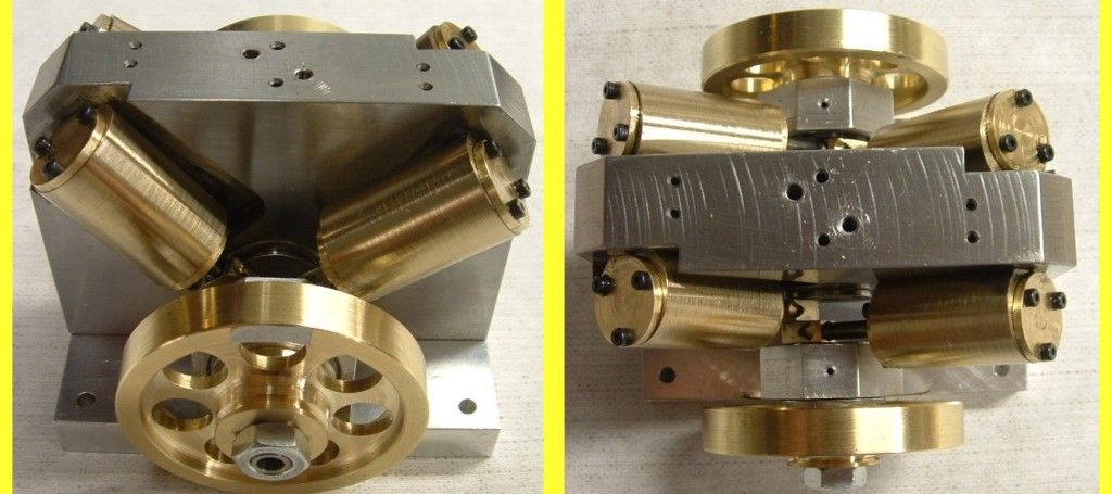
Based on an idea by Spuddevans - I designed a V4 Wobbler using rare earth magnets to secure the cylinders.

It is 10mm bore 15mm stroke - 4 cylinders double acting - the cylinders are at 90° and run in pairs on common journals, the journals are 135° apart so I should get 8 equispaced power strokes per revolution which will allow it to run smooth and slow.

Finally started cutting metal today and got the cylinders done.
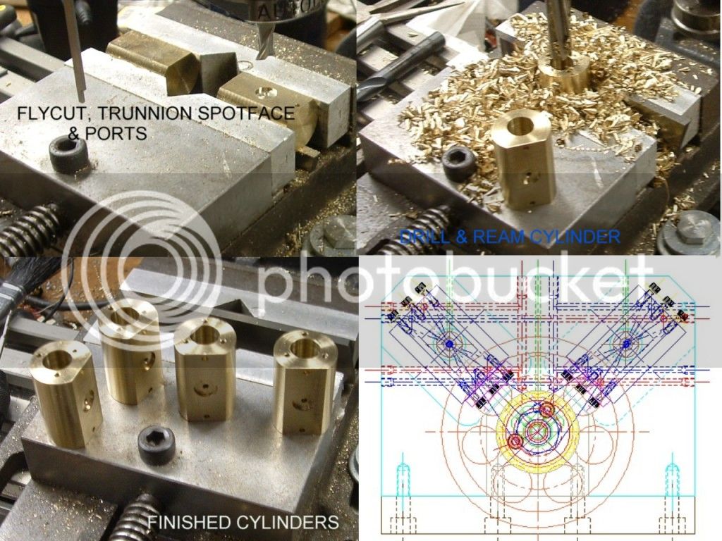
cylinders.jpg


Ran it as a batch job relying on the V notch in my soft jaws to reliably pick up the part with good repeatability - seems to have worked fine.

I made the cylinders out of Ally-Bronze - the minimill didn't much like the 9.5mm drill - but the reaming went fine.

I will post the plans once I'm sure there are no fatal flaws in the design.

Regards,
Ken
 
I will be watching. I like these little wobblers. Looks great so far.

Brock
 
Looking good there Ken, you're off to a good start.

Tim
 
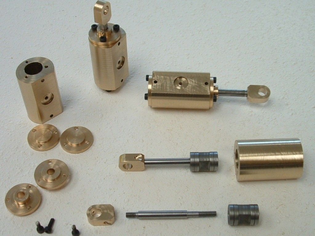
Got the four cylinder assemblies finished.
cylass.jpg

I "cheated" the three drilled holes in the cylinder heads by simply placing them on the cylinder at the last drilling & tapping position (last post) and spot drilled the head in-situ. I then drilled the spot 2mm on my drilling machine and returned it to the cylinder - fitted it in place with a M2 cap screw, 120° out and spot drilled the next hole etc. etc. - saved on having to mount and pitch drill each one.

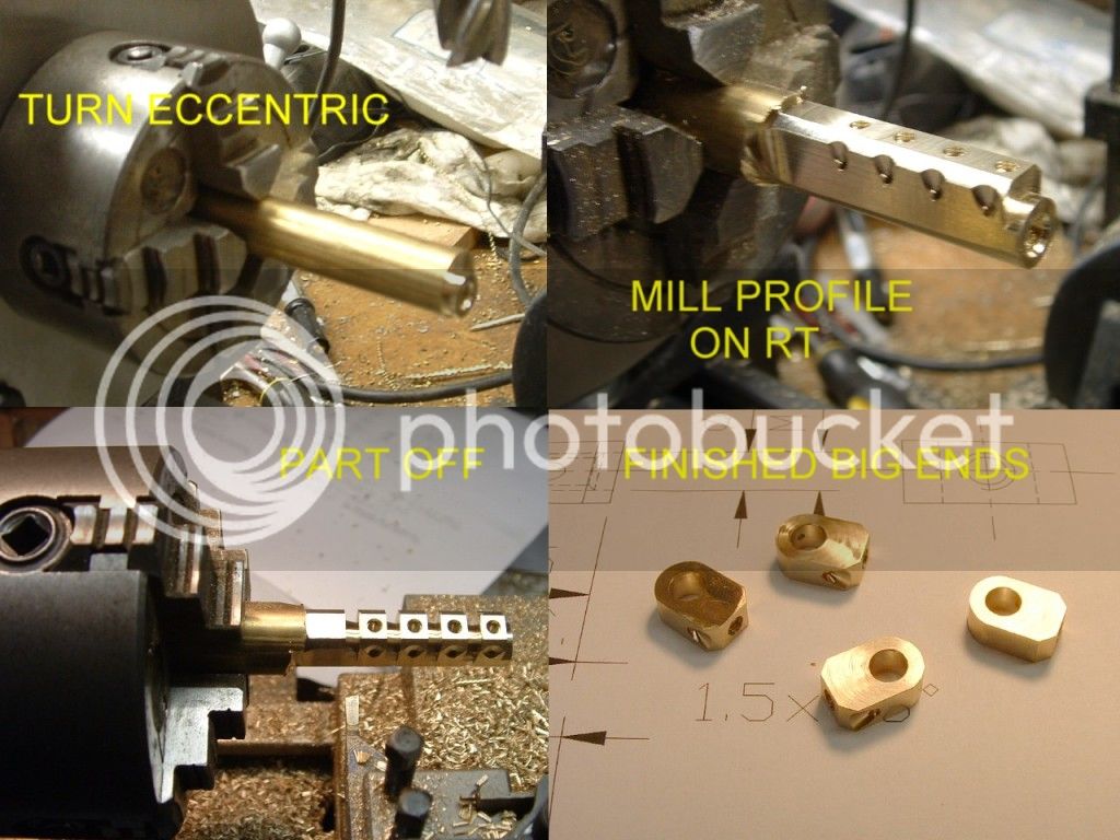
Made the big ends from the smallest barstock possible by first drilling and reaming the bore eccentrically on the lathe with the 4 jaw.

bigends.jpg

Then transplanted the 4 jaw to the rotary table and milled the profile and drilled the holes. Back to the lathe for parting off.
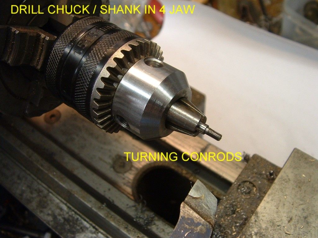
conrod.jpg

Since I don't have an ER collet chuck I turned the rods in a drill chuck I have mounted on a shank (an old shockabsorber rod which has the correct 1/2"20 UNF thread - practically made for the job) mounted in my 4 jaw.

Next job the main body which is a maze of cross drilled holes.

Ken
 
Started on the main body - lots of relatively deep cross drilled holes.

One broken drill could screw the whole thing.

I hope I don't regret designing all the "plumbing internal.

Ken

manifold.JPG
 
Neat design for the main frame Ken.

Ken I said:
I hope I don't regret designing all the "plumbing internal.

You'll only regret it if you didn't try it, and if it all turns out ok then you will have a very neat little engine.


What are you making the body out of?

With mine it was some unknown grade of Ali' so I took the deep drilling very easy, pecking in no more than the diameter of the drill-bit until half-depth, then I went down to half-drillbit "pecks", completely withdrawing the drill with each "peck". A bit tedious I know, but I didn't break a bit. (rubbing a lead pencil along the flutes of the drill helped to stop the Ali from welding itself to the bit too)


Tim
 
The main body is mild steel with bronze bushes for the trunnions, the magnet is a press fit in the bronze to help isolate it magnetically from the body.

The drilling will also be tedious and I will need to be very carefull at the breakthrough points - I'm thinking of pushing a wire through the cross hole to prevent snatching as the drill goes through.

Anybody got any comments on that ?

Regards,
Ken
 
Good going Ken Thm:

I haven't drilled many deep holes in MS with small drills - just a couple in Ali and Bronze, so take with a pinch bag of salt...

If the wire's a close fit in the hole, you might end up with it sticking because of burrs caused by the break-through, and if it's a bit loose, it might be double-jeopardy on break-through as the drill tip suddenly encounters a loose bit that might throw it off-line and snap it in the hole...

I wouldn't trust my drill press for drilling holes like these, as it's got quite a bit of up/down play on the spindle, but with the mill it's not a problem; I just slightly tighten up the quill lock when getting close to break-through to offer a bit of resistance against pulling the drill into the hole and feed a bit slower. I do use a bit of thin wire in the holes to feel when the drill broke through though, as tightening the quill reduces feel on the feed handle.

Kind regards, Arnold
 
Arnold, thanks for the tips. Definitely going to do it in the mill - I use the quill lock trick occasionally. I also have a quill stop which I will set to stop the quill just short of breakthrough and then "micrometer" my way further by backing up the stop.

http://www.homemodelenginemachinist.com/index.php?topic=11917.msg129780#msg129780

I now see the obvious faulty logic of drilling into wires - your logic tells me its a bad idea.

Ken
 
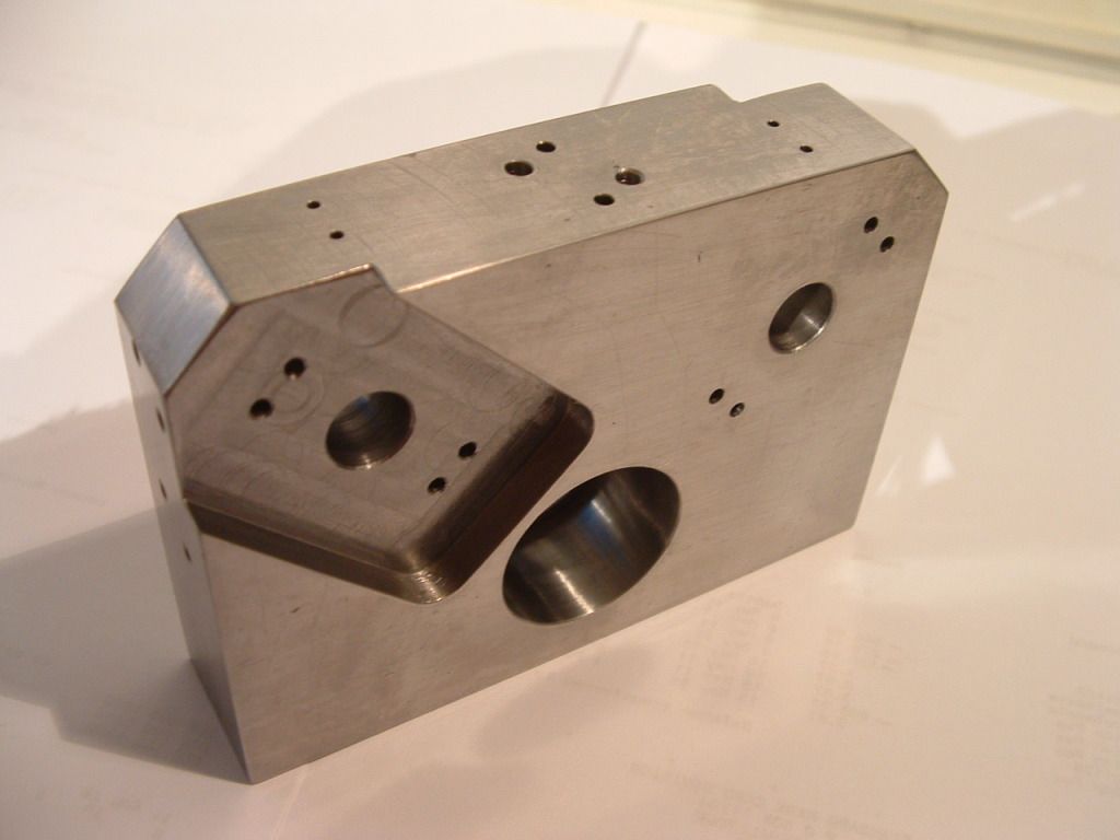
Well I got the block done. Drilling the deep holes (the worst were 2mm diameter x 53mm deep) wasn't as bad as I'd expected.

Block.jpg


Things were going so well I suffered a bout of hubris and on the very last hole I snapped a drill off.

No way to attack it from the oposite side so I knocked it into the larger cross hole and drilled it away with a solid carbide - had to repeat a few times.

In retrospect I should have drilled the smaller deeper holes first and then the larger cross holes (added to build notes).

All's well that ends well - now I've got to add the bushes and magnets and had finish the lands in the pockets which just isn't smooth enough.

Ken
 
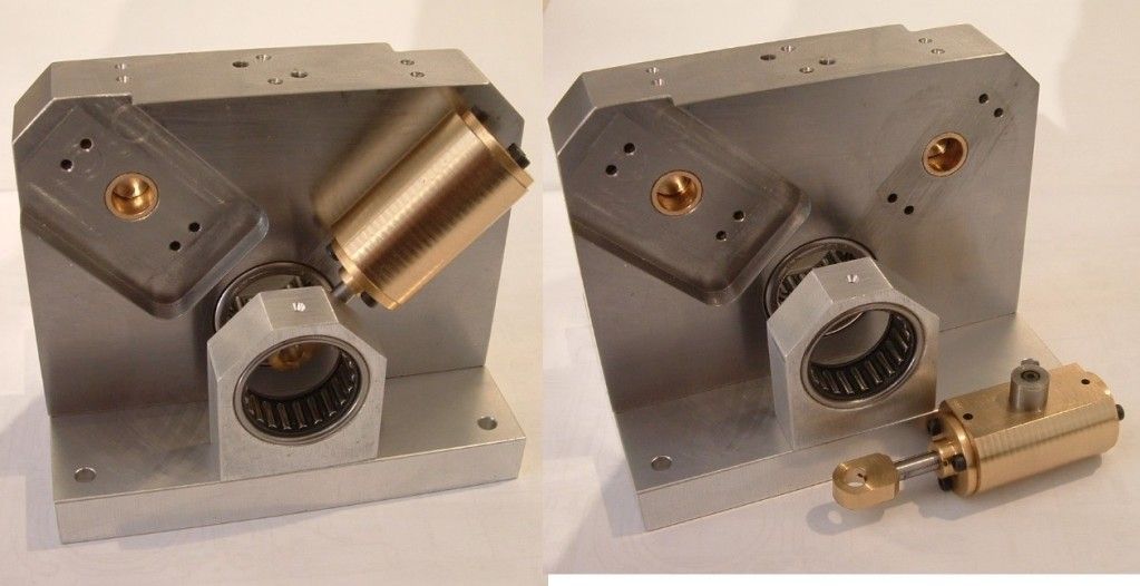
Got the bushes in and press fitted the magnets into place.
Fitup.jpg


The hold down force seems about right with 0.5mm clearance between the trunnion and the magnet.
These Neo magnets are so powerful I expected a bigger gap but obviously the proximity of the steel body is reducing the "available" field strength.

The alginment of the trunnion needs to be spot on - boy am I glad I chose to machine the spot faces at the same time as the running face.

I am begining to think the needle bearings are overkill and that it would work fine with plain bushings.

You can see a number of holes over the trunnions & bearings for applying lube.

 
Ken, thats looking real fine!!! In fact, for a 4 cylinder double acting, (which effectively is an 8 cylinder) you get Karma.----Brian
 

very nice work Ken, it is looking great!

 
Getting close to finishing.

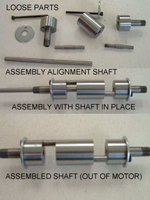
Turned up the crank segments from 20mm bearing shafting - damn tough stuff and the skin is induction hardened down 1mm - my mini lathe protested at cutting through this with a carbide tool but managed. As for parting off - forget it - ended up using a disk grinder and cutting wheel - leaving some stock on for facing off.

These are all the loose parts - the 5mm rod is inserted down the 5mm reamed centre hole to ensure it all lines up on assembly. The crank has to come apart in order to be able to assemble the cylinder big ends onto the big end wrist pins.

Crank1.jpg


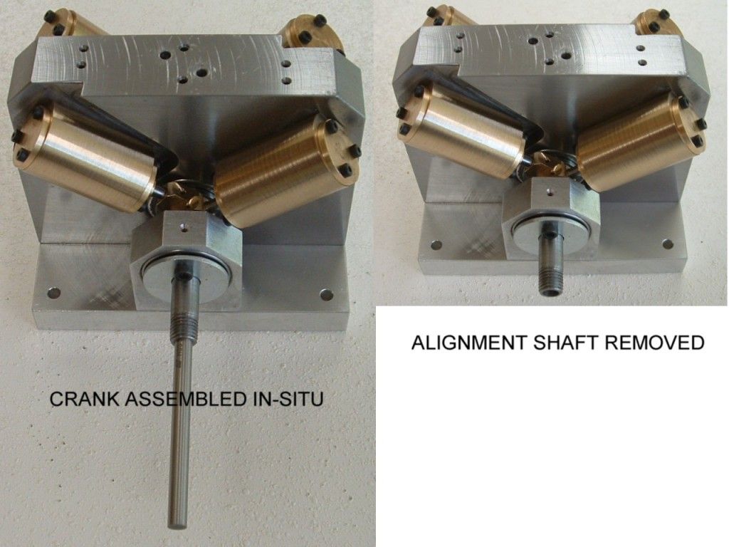
This is the crank assembled out of the motor / in the motor. The bolt head double as location / key for the flywheel - the washers stop the crank from floating - at this stage the cylinders are constraining it.

assy1.jpg


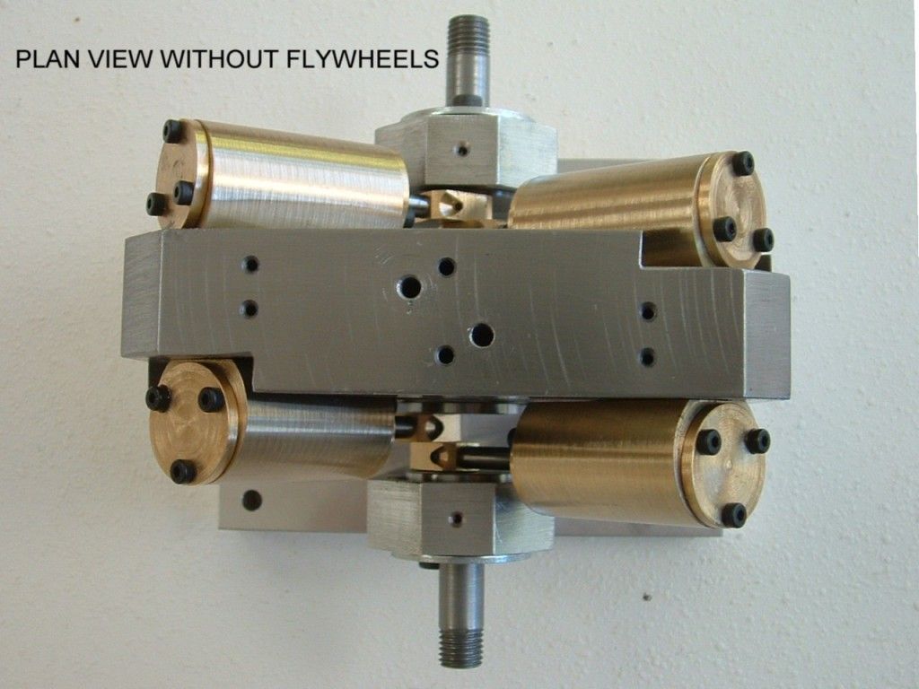
Plan view of the assembled engine without its flywheels - still to be made.

assy2.jpg


I gave it a test run - it runs - but leaks like a sieve - no gaskets or packing etc.

The magnet idea seems to work fine.

Everything is just a little too tight - having worked pretty much spot on - I am going to lenthen the big end journal to free up a little clearance between the big ends an prevent the centre boss of the crank from potentially lifting the cylinders and interfereing with the face seal - the crank float needs to be limited by the thrust washers - not the cylinders.

Going to tackle the flywheels right now.

Ken
 
That looks very clean :bow:
Great job Ken
Brock
 
Ken I said:
Going to tackle the flywheels right now.

with 8 power stokes/rev will it need much of a flywheel?

I ask because Bogs has posted pictures on here of a version, of his, of the French two cylinder that Chuck, Stew, myself and others have made, that has a gearbox in place of the flywheel that directly drives the paddles of a paddle boat

Pete
 
Steamer - video will follow shortly - SWMBO bought me a very nice video camera for my 60th two weeks ago and I haven't used it yet. If I don't use it shortly I'll certainly be in bad odour.

Doubletop - correct ! The flywheel(s) are not really required and are mostly "bling" - my build notes already state this - however I have run it a 2000 rpm but what I really want is for it to tick over really slowly - the motion of the 4 wobbling cyclinders all moving out of synch with each other is far more pleasing than a blur.

I have completed the flywheels and am now just making the new big end pins to add clearance.

I also discovered that the induction hardened zone was proud of the crank surface after facing - no amount of turning will remove it (the tool bounces off it more than the softer substrate) - so I carefully linished the faces (cylindrial or surface grinding would be better).

The raised edge was cocking over the wrist pins and inducing a wobble into the crank assembly.

Regards,
Ken
 
O.K. here's the finished engine.

v4assy.jpg


And a low-res video of it running - starting at a 180 rpm tickover it runs up to 2700 rpm - it is self starting (as it should be) and runs dead smooth - it doesn't even walk around the bench until 2000 rpm

[ame=http://www.youtube.com/watch?v=H26JU7UMQNw]http://www.youtube.com/watch?v=H26JU7UMQNw[/ame]

Even at its slowest there are still video strobe effects which inhibit the proper viewing of the action.

I screwed it down after several frustrating attempts at keeping the tachometer lined up. (Note Tacho reflective tape stuck to upper edge of flywheel.)

The speed is restricted by the 3mm line & restrictor - if I remove the restrictor completely it goes to 3000 rpm.

I think it will go faster once the oscillating faces bed in and stop leaking - but I really want it to go slow.
Initially it wouldn't run below 240 rpm but after an hour I could run it at 180 rpm - my target is 120 rpm or lower - the action is just nice to look at.

Removing the flywheels ups the minimum speed a bit (as you would expect) but otherwise it runs happilly without them.

As I mentioned earlier they are "bling".

Ken
 
Ken-

That's sweet. Worthy of POM in my book.

-Bob
 
Back
Top