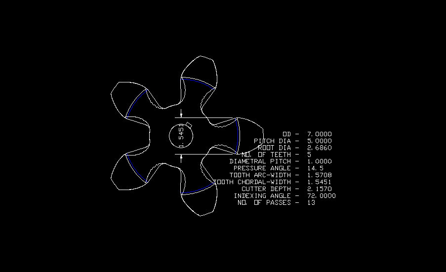
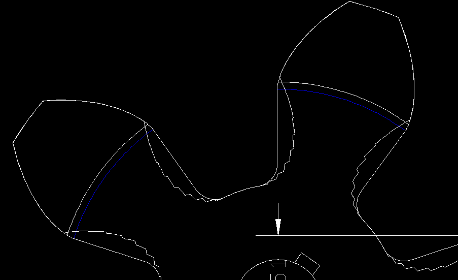
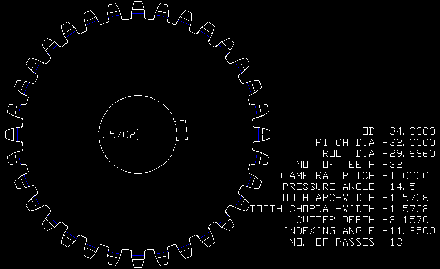
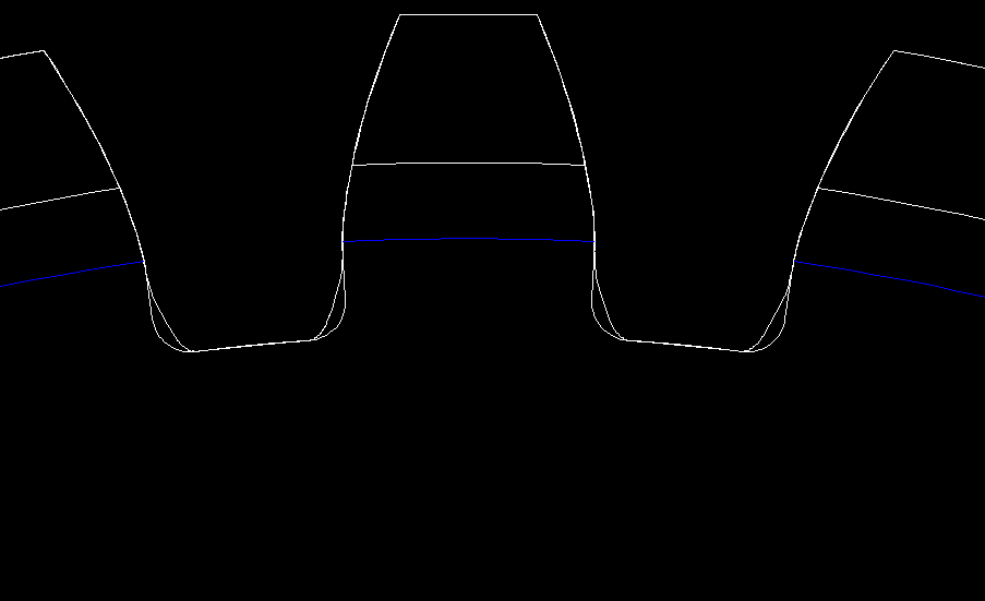
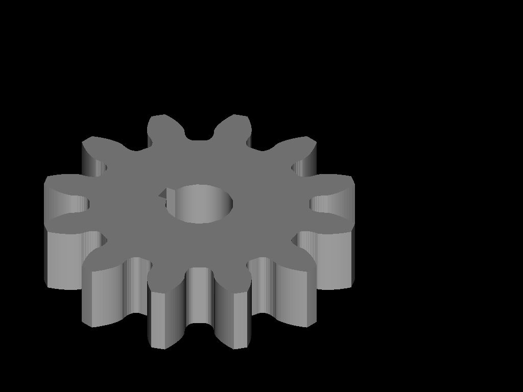
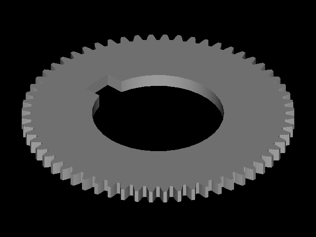
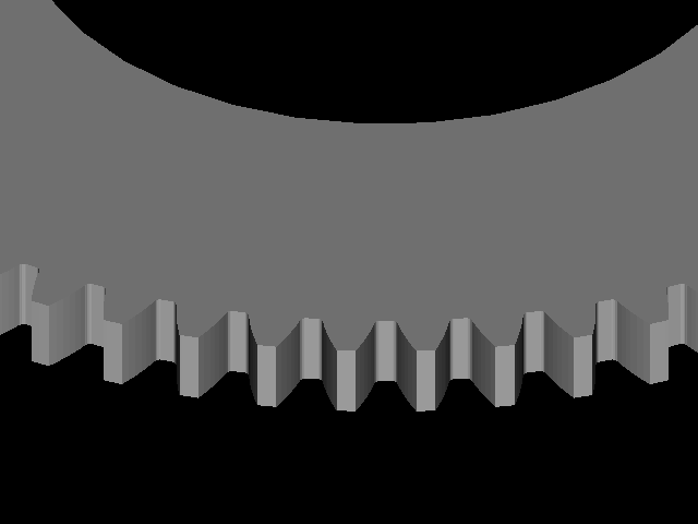
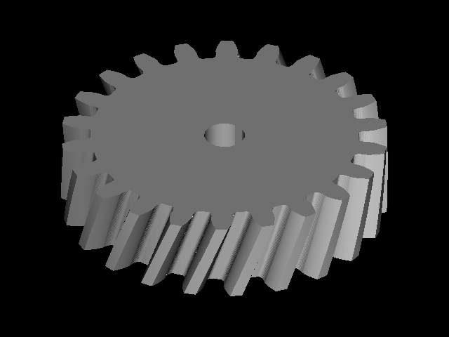
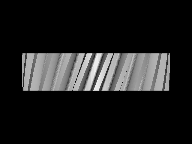
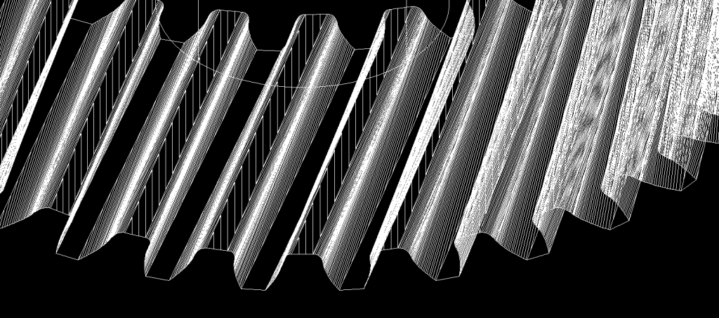
Has anyone out there tried to automate gear drawing in 3D? I've been toying with a few routines to draw:

Rich
- Spur gears (internal and external)
- Helical Gears
- Miter gears
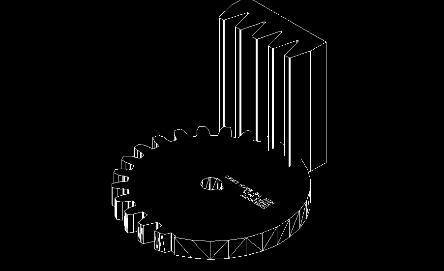
- Draw the hobs using a rack pattern and extrude into a solid
- (for helical gears I extruded at a 20degree angle in the "Z" axis)
- Make the "Z" values way thicker than you'd ever need
- center the tip of the middle tooth on the 0,0,0 x.y.z point and then save the hob drawing (it gets inserted into the drawing file as the teeth are being generated)
- For the miter gears your solid hob gets extruded with the correct taper i.e. 45degrees (I haven't done this yet, but I'm sure it's not a problem)
- All hobs are drawn at 1 diametral pitch, then scaled down automatically depending on the user input for a particular gear
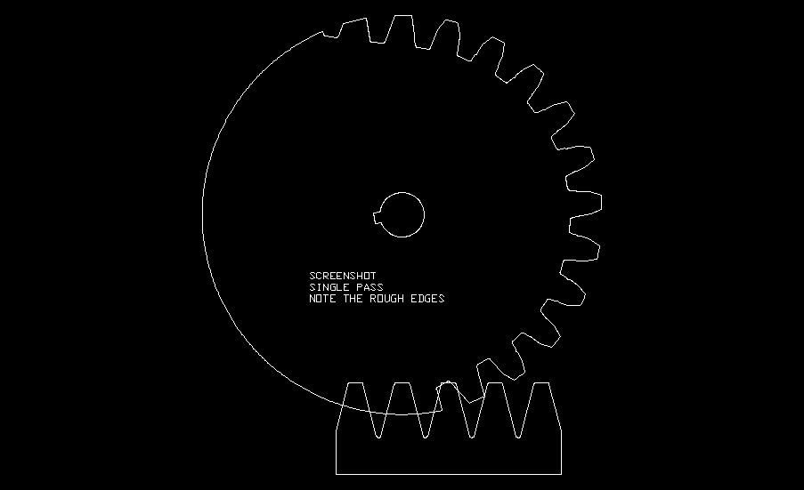
- A solid cylinder is drawn based on user input...no of teeth, DP, shaft size, thickness of blank using 0,0,0 coordinates for the center.
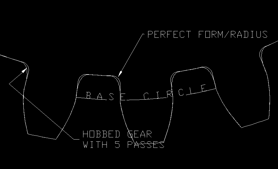
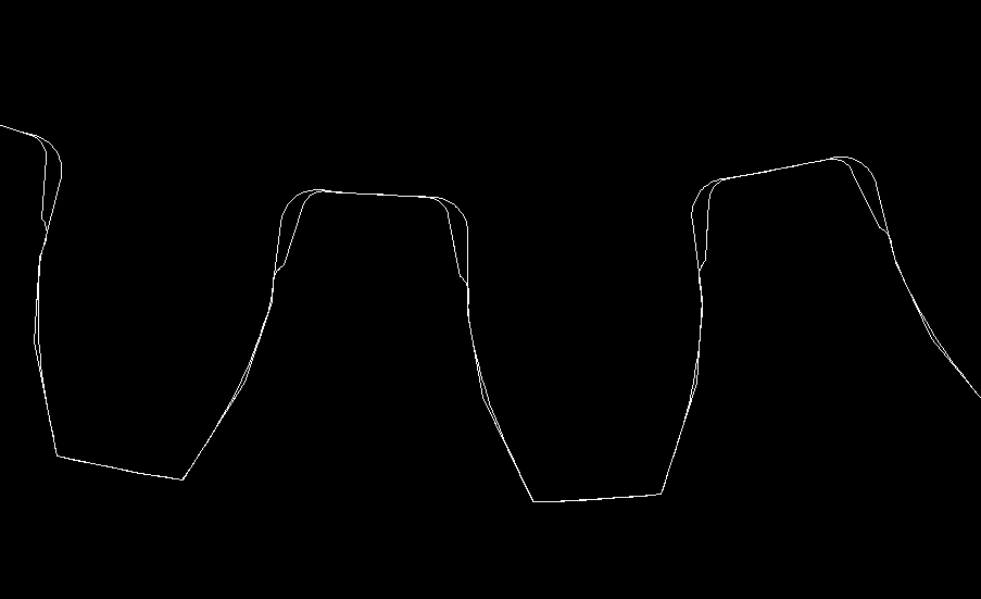
- User is asked for number of passes (imaginary number of flutes of the hob) to simulate the simultaneous rotation of the blank and movement of the hob.
- Program starts by inserting the hob at the cutting depth, then subtracts the hob from the cylinder. This reveals the first "cut" and the hob disappears.
- The blank is rotated (1 tooth/no. of passes)... say 1/12th of a tooth if you chose 12 passes.
- Next insertion point for the hob is calculated to be ...1/12th of the circular pitch if you chose 12 passes. For example...On the screen you see the blank rotate and the hob appears/disappears for each "cut".
- This repeats until the gear is finished. It's about as slow as a hobbing machine, but it's cool to see the teeth being formed as the blank rotates. You can also run the program in a "perspective" view to see it in 3D if you want.


Rich
Last edited:


