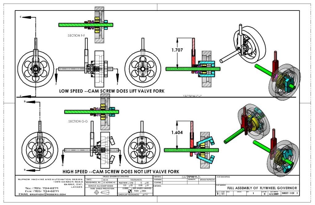
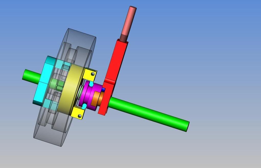
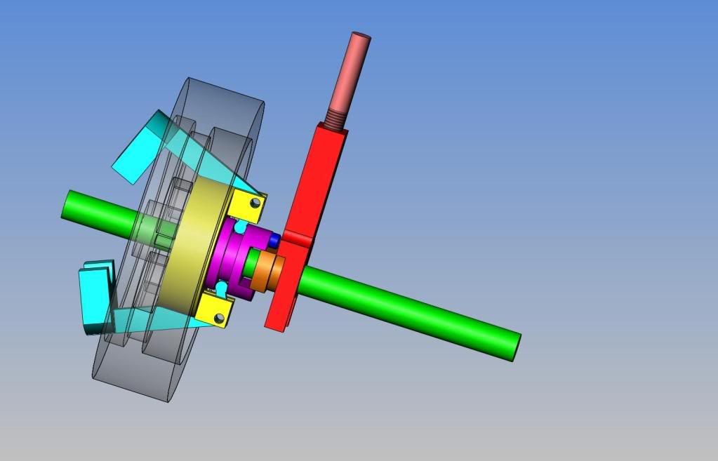
I have been studying on the flywheel governor that was posted by Putputman, Superfast, and partly by "Chuck". This is not an easy thing to get your head around. The purpose is to either engage the rod which opens/closes the valve which allows the engine to "fire" or not to engage it so that the engine only coasts. I had to model it all to get an understanding of what was actually happening there. In essence, at low speed, the compression spring holds the weights on the ends of the counterweight arms in close to the crankshaft, and the small "cam-screw" does interact with the valve rod and lift it up and down, allowing the engine to "fire". As soon as it fires, the engine revs up and centrifugal forcr forces the weights to fly out away from the crankshaft.--This in turn rotates the weight arms which the weights are soldered to to pivot, and pull the purple sliding ring in closer to the yellow disc which is bolted to the flywheel----this compresses the compression spring, and the purple sliding hub which has the dark blue "cam screw" attached to it slides closer to the flywheel so that the head of the "cam screw" no longer reaches the valve fork to lift it. Since the engine will not then fire, the engine slows down, centrifual force on the weights is not so great, and the compression spring expands and moves everything back into the "low speed" mode.


View attachment FULL ASSEMBLY OF FLYWHEEL GOVERNOR.PDF

View attachment FULL ASSEMBLY OF FLYWHEEL GOVERNOR-3.PDF


View attachment FULL ASSEMBLY OF FLYWHEEL GOVERNOR.PDF

View attachment FULL ASSEMBLY OF FLYWHEEL GOVERNOR-3.PDF


![DreamPlan Home Design and Landscaping Software Free for Windows [PC Download]](https://m.media-amazon.com/images/I/51kvZH2dVLL._SL500_.jpg)


