rcplanebuilder
Active Member
- Joined
- Aug 29, 2009
- Messages
- 30
- Reaction score
- 0
Well, after doing some research and viewing others handiwork here, I decided to build my own version of a tool post grinder.
Parameters:
Design parameters are everything IMO. Everyone has different skill levels, different machinery, different budgets, and different purposes to suit. With that, nobody's design is perfect.
1. I have a small lathe. A Grizzly 9X19 to be exact.
2. I hate anything that is a hassle.
3. I don't think I will be needing a tool post grinder every day. Rarely at best. But, I do need one occasionally, and therefore it should be simple and quick to use.
4. Factoring in #'s 1, 2, and 3, I don't want to spend a lot of dough on a TP grinder.
So here is what I came up with.
The basic idea was to use the existing dovetail tool holder, to mount and use the TP grinder. The thought of having to take the entire tool post off of the machine just to set up a grinder doesn't do it for me.
On that note, I see A LOT of garbage tool posts installed on these lathes here. :-X FWIW, I will post a "how to" if needed on adapting the 100 series dovetail tool posts onto this small lathe. Yes, they fit perfectly, and it is very simple to install, and it is like night and day with the resulting usefulness of this machine. So technically, this is step 2 in the upgrade to the tool post. It's an expansion pack for the original modification. The 100 series tool posts are a measly $100 on sale at Enco, and they come with 5 tool holders, and their net worth is a million bucks in usefulness. Add a few more holders at $23 dollars each, and it's drop and go. Just as I want my TP grinder to be.
So, the basic design revolved around the dovetail tool post. Specifically, the 5/8 round hole boring bar holder is all but useless. I have 1/4 inch, 1/2 inch, and 3/4 inch, boring bars, and... it's useless as... (insert colorful metaphor here)
Searching for parts was easy in some ways, and tough in others. In fact, I think I am looking for some upgrades already.
Here are the parts I settled on for the initial design.

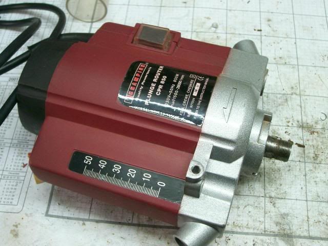
The motor is the trickiest part. After some errant purchases at the local "flea market store", I found myself staring at an old starter motor for model airplanes, which I have stored, and moved, and tried to give away to other R/C fliers for years. So, it has been an unneeded "Spare" lying about for way too long. The revelation was in my tunnel vision of A/C motors. Why not 12 Volt D/C? I put some tape stripes on the pulley, and put a tachometer on it, and it was running at 5,600 RPM's with no load. Hmmm. Game on.
So, I started with a blue print. This is my blue print, I drew it, I dimensioned it, I own it. If I patent it, everyone who wanted one would just build their own anyway, copying it. Nobody will buy it, because everyone wants to make their own anyway. Therefore, if you want a DXF, I'll send you one. Hack away builders!
(I will post it here, having trouble converting it to postable image)

Then I started turning the shaft and things.

For die cutting the threads, this is what I use. Simple, and parts on hand. Put the die in a socket. As you thread it on, you can lock the tail stock, and the die will slide up the inside of the socket. You can just turn out some more lead on the chuck if needed. You can watch it, and you already have the sockets on hand for any sized die.

I bored the dovetail holder.

I found it broke through some holes, sized for using the 6202 bearings I got at the Ax Man (for free with purchase of my new mill chair), lol. But, no big deal, if it bothers you, use smaller bearings. The trade off will be a smaller shaft size with less rigidity though. The metal in these things is kind of cheesy and cast like, but not really here nor there. :big:

I used the 4 jaw for the first time, and I was less than confident that the bearings would be bored true. I did face the first end, so that hopefully the other end would square up against the chuck better. These holders are ripped out en-mass at the T Aiwan machining company, and are not square by any means. Just indicating in a hole with a corn cob finish is a thrill, lol. But, it worked great.
Pulley design was a coin toss. I had some tooth pulleys, and a belt that was longer than I wanted, but the friction would be low, and the pulley adaptation would be tricky. O-rings work, but milling and lathing at the same time for round grooves is not an option here yet. And the starter motor already had a v-grove in it, but I knew loads would go up turning a v-belt. ....
The v-belt won out, but it can also run an O-ring too. More on that later.

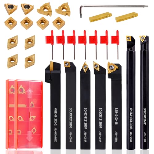
The cutoff shown here is an insert design, it fits in the tool post, and is reversible from right to left. The trick is keeping blade pressure up, and it cuts like gangbusters with little chatter at all. Turn slow, push firmly. Reasonably priced too.
Anyway, here are the basic pieces ready for assembly.


Some things to note here. I turned a shoulder on the shaft for a press fit to the bearing, and turned the rest of the shaft about .002" under sized. Then I knurled the bearing area to provide a press fit for the second bearing. This way, the bearings slide easily up the shaft to the point where they need to be, without fighting you the whole way. Two shoulders would work too. But .... A. I screwed up. and B. I wanted to try my knurling tool anyway.
Here is what it looks like assembled, lying on the bench.

And the drive end.

So, now all I have to do, is remove the tool from the tool post, and drop this assembly in place, lock the dovetail, and plug it in.... well, actually it's more like .....go get the battery from the boat that is in storage, and the battery charger, and.... lol. But, I have a plan for that! :big:
Business end. I can see what I am doing, and nothing gets in the way of anything else.
Except for. 1. the cord is precariously incomplete and strays a bit close to the chuck for my liking. 2. The wheel attach bolt (arbor/adapter) needs to be a button head cap screw, so it doesn't kill me when it hits the chuck, like it would now. and 3. It just ain't done quite yet.

The drive end. You will note that I have left some tail stock on the shaft for plans B, C, and D, if needed. lol. Gear ratio pulleys, etc...

And a front view, for size reference, et al....

Now, as for some pending verdicts.
The v-belt really soaks up some power and RPM's. I think it will only turn at about 3,500 RPM's with this heavy of a belt. It also draws a whopping 10 amps with it installed.
Not to fret, using a large O-ring in the same v-groove, the RPM's raise to about 4,500, and it only draws about 7.3 amps.
However. It is apparent that this is an intermittent duty motor. How do I know this? Well, it is designed for starting model airplane engines, then you go fly for 15 minutes. Also, you'll note a distinct lack of cooling holes in the motor, and the absence of a cooling fan. Hmmm.
The case halves are riveted together, so, although designing and making a centrifugal fan on the pulley side would be "easy peasy lemon squeezey", the disassembly of this motor to cut holes is another story.
On the other hand, this is a DC motor, thereby, I can purchase a 15 or 20 amp Variac (variable DC transformer), and run this thing at voltages of up to (probably) 24 volts and have speed control to boot. However, increased volts means increased amps, and .... increased heat. My "Good" starter is rated at 12-24 volts.
One could argue, that this motor was free, and had one foot in the garbage can anyway, so why not test the limits. And in fact, I intend to do so. However, breaking it, by disassembling it to add cooling holes, before I even get to use it might prove disappointing at best....
The other issues are learning which wheels I want, etc... The 2 freebies I have are coarse, and somewhat less coarse IMO. I am not getting a finish anywhere near the factory finish on a shoulder bolt, for example.
But... I am grinding. and it takes 2 seconds to change from a cutting tool, to a tool grinder. And that's saying something.
Any, and all, ideas and comments are welcome. If you hate it, you can even bring that too... lol
Cheers,
T
Parameters:
Design parameters are everything IMO. Everyone has different skill levels, different machinery, different budgets, and different purposes to suit. With that, nobody's design is perfect.
1. I have a small lathe. A Grizzly 9X19 to be exact.
2. I hate anything that is a hassle.
3. I don't think I will be needing a tool post grinder every day. Rarely at best. But, I do need one occasionally, and therefore it should be simple and quick to use.
4. Factoring in #'s 1, 2, and 3, I don't want to spend a lot of dough on a TP grinder.
So here is what I came up with.
The basic idea was to use the existing dovetail tool holder, to mount and use the TP grinder. The thought of having to take the entire tool post off of the machine just to set up a grinder doesn't do it for me.
On that note, I see A LOT of garbage tool posts installed on these lathes here. :-X FWIW, I will post a "how to" if needed on adapting the 100 series dovetail tool posts onto this small lathe. Yes, they fit perfectly, and it is very simple to install, and it is like night and day with the resulting usefulness of this machine. So technically, this is step 2 in the upgrade to the tool post. It's an expansion pack for the original modification. The 100 series tool posts are a measly $100 on sale at Enco, and they come with 5 tool holders, and their net worth is a million bucks in usefulness. Add a few more holders at $23 dollars each, and it's drop and go. Just as I want my TP grinder to be.
So, the basic design revolved around the dovetail tool post. Specifically, the 5/8 round hole boring bar holder is all but useless. I have 1/4 inch, 1/2 inch, and 3/4 inch, boring bars, and... it's useless as... (insert colorful metaphor here)
Searching for parts was easy in some ways, and tough in others. In fact, I think I am looking for some upgrades already.
Here are the parts I settled on for the initial design.

The motor is the trickiest part. After some errant purchases at the local "flea market store", I found myself staring at an old starter motor for model airplanes, which I have stored, and moved, and tried to give away to other R/C fliers for years. So, it has been an unneeded "Spare" lying about for way too long. The revelation was in my tunnel vision of A/C motors. Why not 12 Volt D/C? I put some tape stripes on the pulley, and put a tachometer on it, and it was running at 5,600 RPM's with no load. Hmmm. Game on.
So, I started with a blue print. This is my blue print, I drew it, I dimensioned it, I own it. If I patent it, everyone who wanted one would just build their own anyway, copying it. Nobody will buy it, because everyone wants to make their own anyway. Therefore, if you want a DXF, I'll send you one. Hack away builders!
(I will post it here, having trouble converting it to postable image)

Then I started turning the shaft and things.

For die cutting the threads, this is what I use. Simple, and parts on hand. Put the die in a socket. As you thread it on, you can lock the tail stock, and the die will slide up the inside of the socket. You can just turn out some more lead on the chuck if needed. You can watch it, and you already have the sockets on hand for any sized die.

I bored the dovetail holder.

I found it broke through some holes, sized for using the 6202 bearings I got at the Ax Man (for free with purchase of my new mill chair), lol. But, no big deal, if it bothers you, use smaller bearings. The trade off will be a smaller shaft size with less rigidity though. The metal in these things is kind of cheesy and cast like, but not really here nor there. :big:

I used the 4 jaw for the first time, and I was less than confident that the bearings would be bored true. I did face the first end, so that hopefully the other end would square up against the chuck better. These holders are ripped out en-mass at the T Aiwan machining company, and are not square by any means. Just indicating in a hole with a corn cob finish is a thrill, lol. But, it worked great.
Pulley design was a coin toss. I had some tooth pulleys, and a belt that was longer than I wanted, but the friction would be low, and the pulley adaptation would be tricky. O-rings work, but milling and lathing at the same time for round grooves is not an option here yet. And the starter motor already had a v-grove in it, but I knew loads would go up turning a v-belt. ....
The v-belt won out, but it can also run an O-ring too. More on that later.

The cutoff shown here is an insert design, it fits in the tool post, and is reversible from right to left. The trick is keeping blade pressure up, and it cuts like gangbusters with little chatter at all. Turn slow, push firmly. Reasonably priced too.
Anyway, here are the basic pieces ready for assembly.


Some things to note here. I turned a shoulder on the shaft for a press fit to the bearing, and turned the rest of the shaft about .002" under sized. Then I knurled the bearing area to provide a press fit for the second bearing. This way, the bearings slide easily up the shaft to the point where they need to be, without fighting you the whole way. Two shoulders would work too. But .... A. I screwed up. and B. I wanted to try my knurling tool anyway.
Here is what it looks like assembled, lying on the bench.

And the drive end.

So, now all I have to do, is remove the tool from the tool post, and drop this assembly in place, lock the dovetail, and plug it in.... well, actually it's more like .....go get the battery from the boat that is in storage, and the battery charger, and.... lol. But, I have a plan for that! :big:
Business end. I can see what I am doing, and nothing gets in the way of anything else.
Except for. 1. the cord is precariously incomplete and strays a bit close to the chuck for my liking. 2. The wheel attach bolt (arbor/adapter) needs to be a button head cap screw, so it doesn't kill me when it hits the chuck, like it would now. and 3. It just ain't done quite yet.

The drive end. You will note that I have left some tail stock on the shaft for plans B, C, and D, if needed. lol. Gear ratio pulleys, etc...

And a front view, for size reference, et al....

Now, as for some pending verdicts.
The v-belt really soaks up some power and RPM's. I think it will only turn at about 3,500 RPM's with this heavy of a belt. It also draws a whopping 10 amps with it installed.
Not to fret, using a large O-ring in the same v-groove, the RPM's raise to about 4,500, and it only draws about 7.3 amps.
However. It is apparent that this is an intermittent duty motor. How do I know this? Well, it is designed for starting model airplane engines, then you go fly for 15 minutes. Also, you'll note a distinct lack of cooling holes in the motor, and the absence of a cooling fan. Hmmm.
The case halves are riveted together, so, although designing and making a centrifugal fan on the pulley side would be "easy peasy lemon squeezey", the disassembly of this motor to cut holes is another story.
On the other hand, this is a DC motor, thereby, I can purchase a 15 or 20 amp Variac (variable DC transformer), and run this thing at voltages of up to (probably) 24 volts and have speed control to boot. However, increased volts means increased amps, and .... increased heat. My "Good" starter is rated at 12-24 volts.
One could argue, that this motor was free, and had one foot in the garbage can anyway, so why not test the limits. And in fact, I intend to do so. However, breaking it, by disassembling it to add cooling holes, before I even get to use it might prove disappointing at best....
The other issues are learning which wheels I want, etc... The 2 freebies I have are coarse, and somewhat less coarse IMO. I am not getting a finish anywhere near the factory finish on a shoulder bolt, for example.
But... I am grinding. and it takes 2 seconds to change from a cutting tool, to a tool grinder. And that's saying something.
Any, and all, ideas and comments are welcome. If you hate it, you can even bring that too... lol
Cheers,
T


![DreamPlan Home Design and Landscaping Software Free for Windows [PC Download]](https://m.media-amazon.com/images/I/51kvZH2dVLL._SL500_.jpg)


![MeshMagic 3D Free 3D Modeling Software [Download]](https://m.media-amazon.com/images/I/B1U+p8ewjGS._SL500_.png)