spacy
Member
pm replied to


![DreamPlan Home Design and Landscaping Software Free for Windows [PC Download]](https://m.media-amazon.com/images/I/51kvZH2dVLL._SL500_.jpg)


We think the engine for the boat was 5 inch bore, never did take the head off to measure.
Here's a link to the engine on a dry run.
Thought the crank was cast iron, wrong, was a low carbon cast steel, miserable to machine. Tried every grind in HSS I could think of and a couple of inserts, nothing gave a nice finish. In the end I rough cut it with a sharp pointed tool then file and emery close to size and lapped to final dia. In hind sight I should have cut one out of plate.
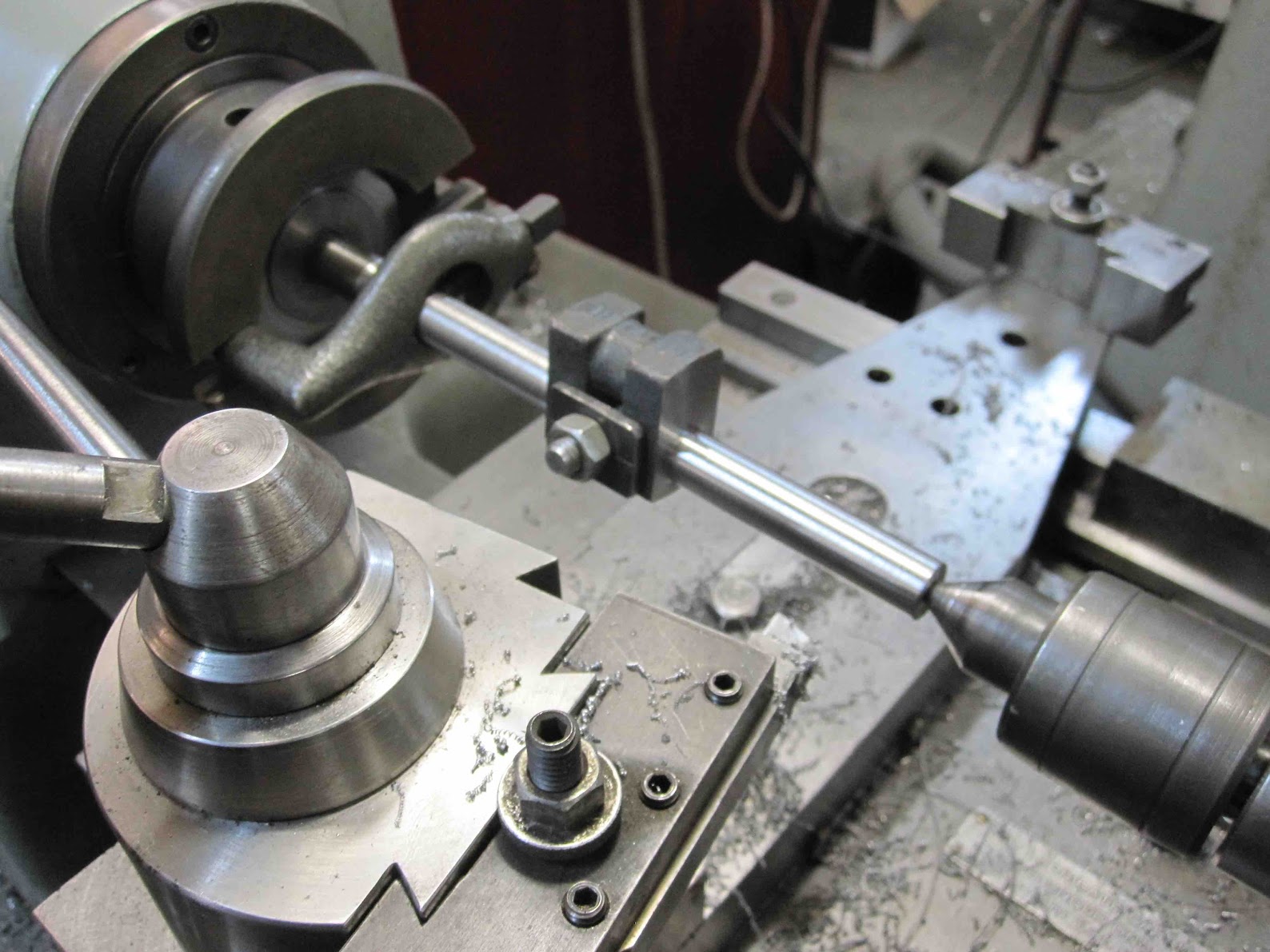
To machine the throw I made a jig that allowed one end to go inside and a grove to hold the throw with a light press fit.
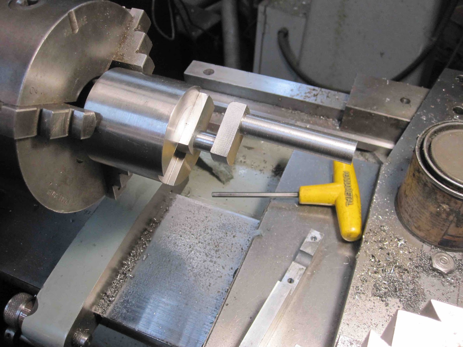
Decided to open up the crank bearings on the mill with a drill and reamer. I fastened a block to scrap to the bed, drilled and reamed it to 3/8ths, then mounted the crank case with a dowel between a collet and the bored hole. This aligned the bore to machine. I then brought an angle plate up to it and clamped everything.
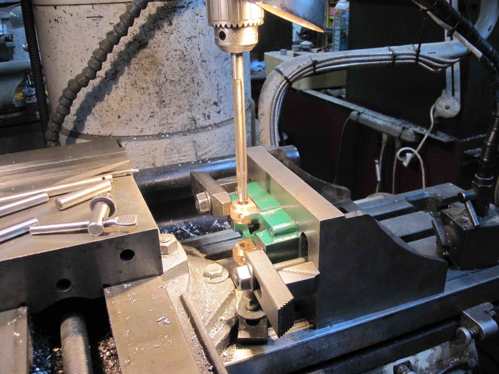
Have to remove a bit of the casting in the crank case, The throws don't clear at the bottom, Oops.
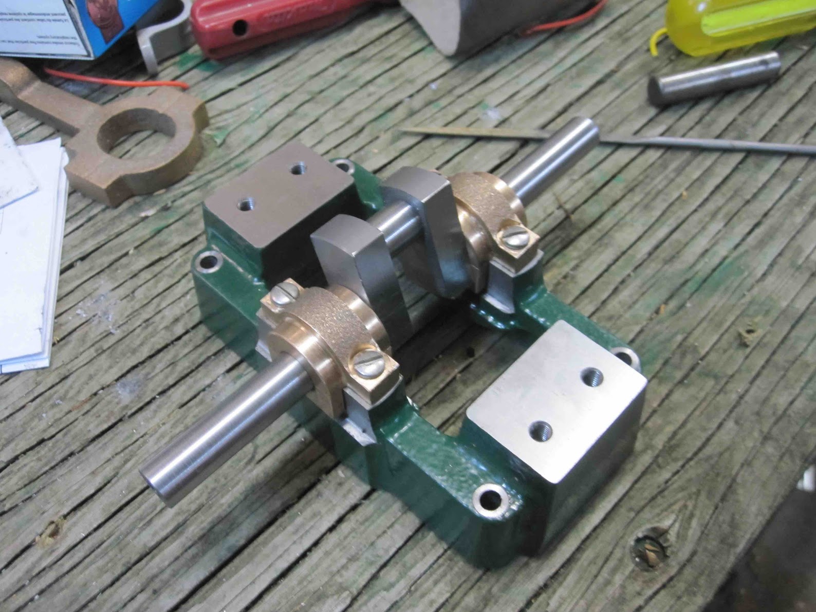
Had a 1 thou over reamer, and lapped the crank to 2 tenths under, so have 0.0012 clearance. It rotates but is that going to be enough clearance for oil.
Thanks for watching.
Greg
I am building a #4 right now and have noticed a similar problem with the porting cores on the cylinder. They are too close together so the exhaust port will be way too narrow. I like your fix. I'll do that. I also saw in an old catalog that the #4 had a 4-1/2" flywheel. This kit came with a 5" (probably from a Stuart #9) and the bases are not tall enough. It will need a little plinth, or a small diameter flywheel. Great job on yours and thanks for showing this.This thing is eating up too much of my precious time, bloody thing is addictive.
The intake ports were cored in the cylinder but were too far apart at the valve end. Had to cut the openings closer to the exhaust port, but this meant that the valve wouldn't cover the end.
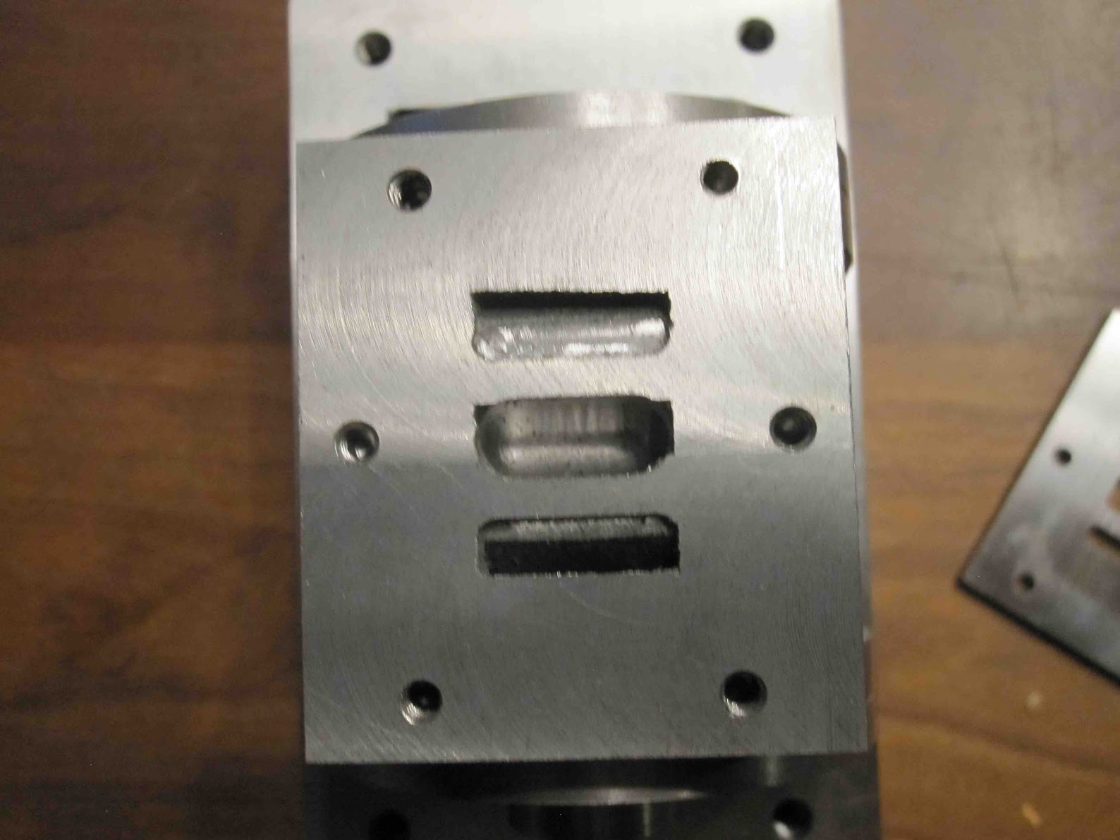
Cut a thin slice from a scrap of cast iron and ground it to .1 thick, then cut the ports with the correct spacing and size.
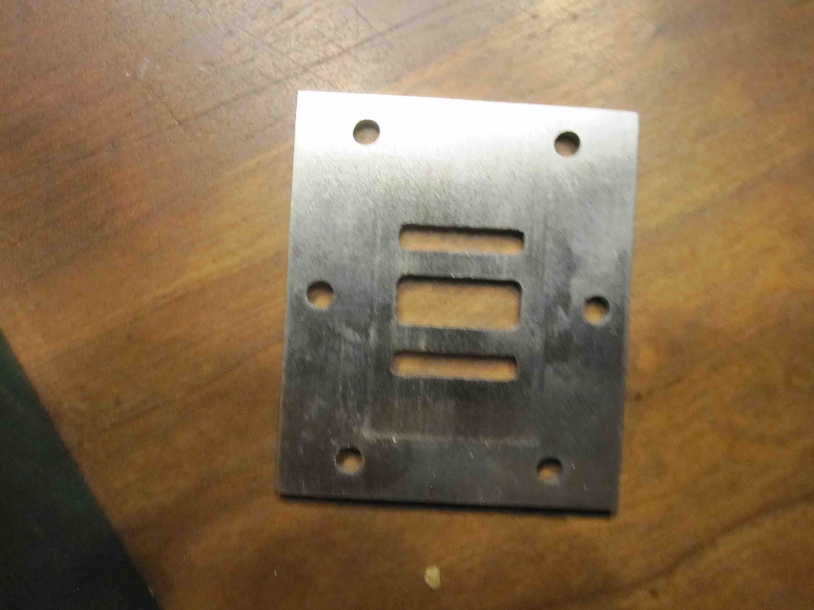
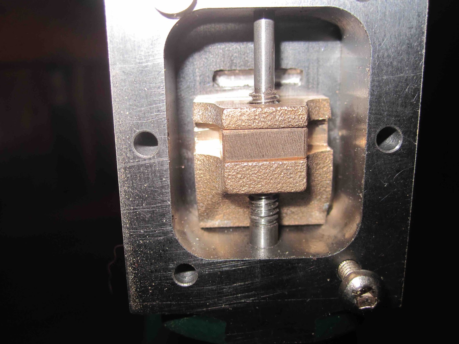
Sandwiches nicely behind the valve chest.
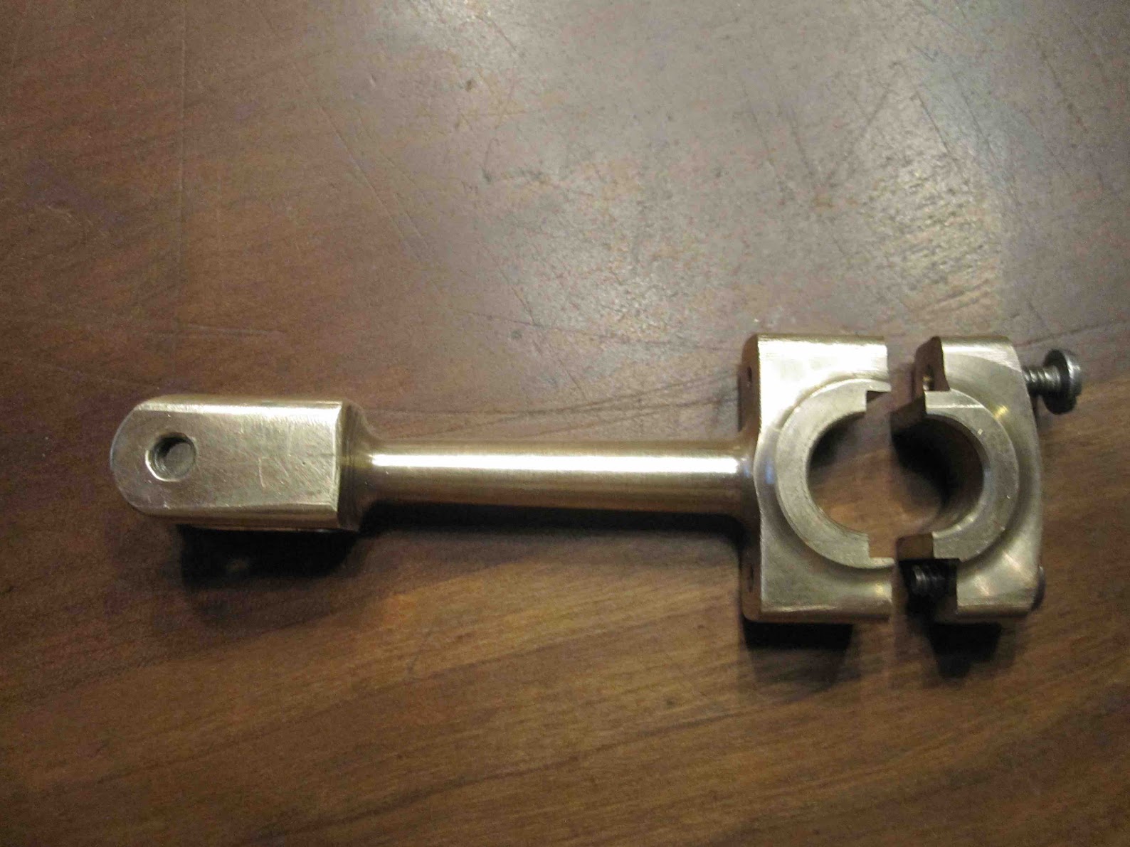
Made the connecting rod today. The drawings show the joint straight across the journal, decided to step the joint to locate the haves and not rely on the bolts.
Starting to look like an engine.
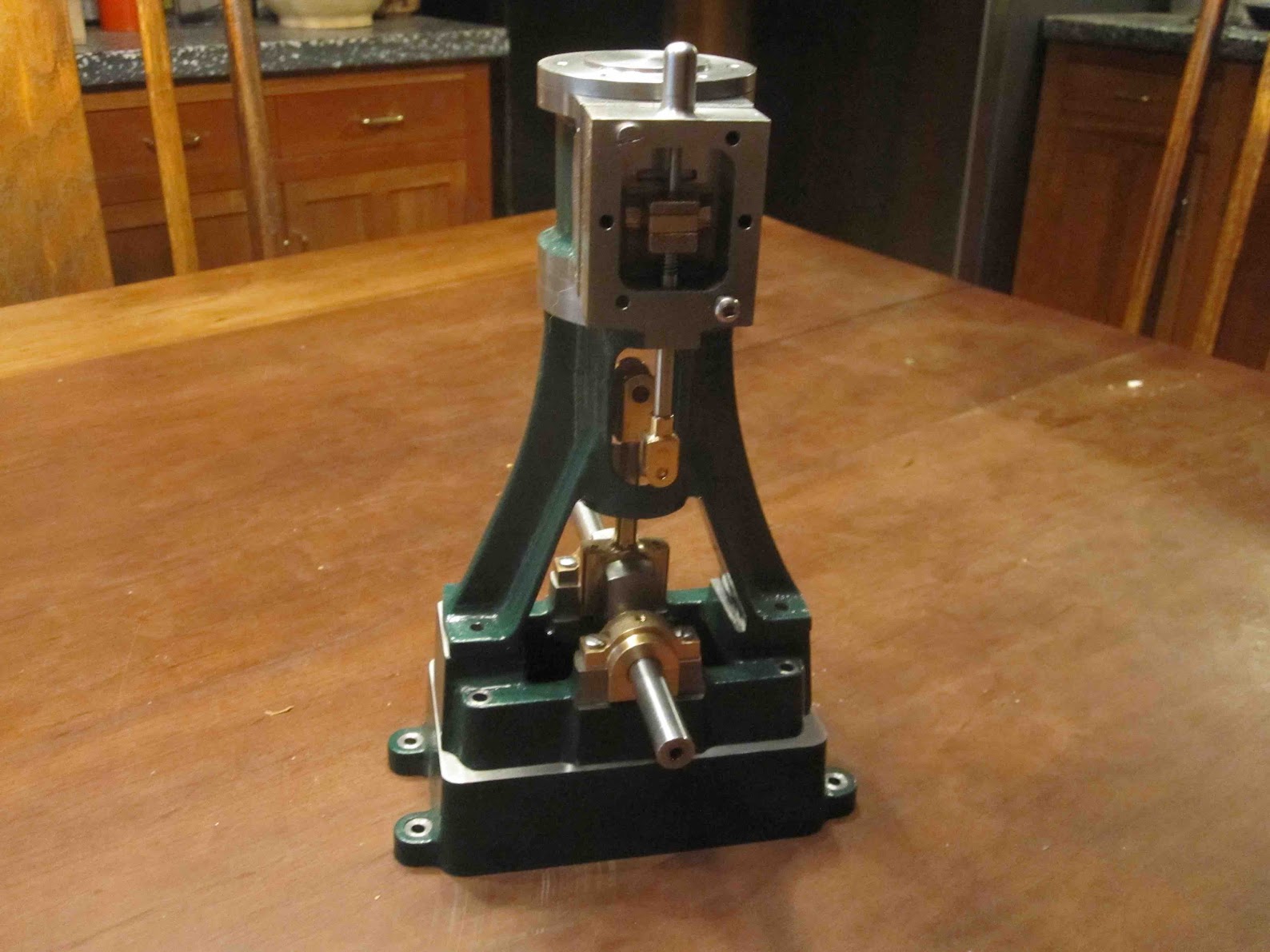
Know I could machine a full sized one faster. lol
Thanks for looking
Greg