Squaring Stock

Home Model Engine Machinist Forum

Help Support Home Model Engine Machinist Forum:

This site may earn a commission from merchant affiliate links, including eBay, Amazon, and others.

glue-itcom

Well-Known Member
Joined
Apr 10, 2013
Messages
216
Reaction score
300
How often do you need to square a piece of stock? This process was written by Alan at Woody's Workshop:

Step 1
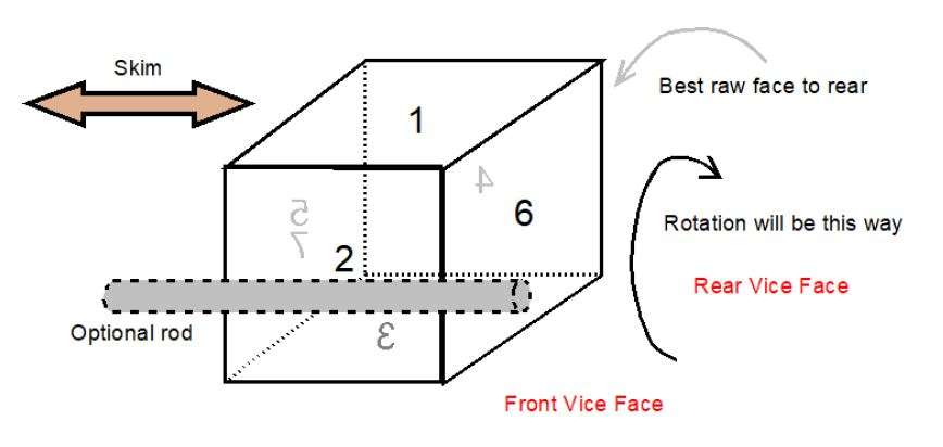
Inspect the stock and pick the side that has the surface that is the flattest and most appropriate for the end result you are looking for. Place this surface against the rear vice jaw. This eventually be machined to become Side 4 but for the moment just skim the top surface which will now become Side 1.
squaring-stock-1.jpg
 
This is a different approach, but worth a look:
Thanks, I'm sure there are lots of different approaches. Would be great to share as many as we can.

Some methods will gel with different people.
 
I would add that a half round against the moving jaw helps when the stock is not square. Half round pushes against the center of the stock , this usually keeps the work from moving up or down until another face is flat. Wood or metal will work .
mike
 
I would add that a half round against the moving jaw helps when the stock is not square. Half round pushes against the center of the stock , this usually keeps the work from moving up or down until another face is flat. Wood or metal will work .
mike
Agree, this is a good tip for any work in a vice or machine vice
 
The first thing I did was to make sure my vice jaws were true vertically using a DTI because if they are not then you will be chasing your tail ( been there ) you cannot assume that because it is a new vice that it is correct and using the half round method or any other method won't alter the result.

Paul
 
What I see missing from all these procedures is to set your material on parallels on the same side as your none moving jaw until you have at least 2 sides milled then you can add your second parallel
Thanks
Tom
 
Peter at Edge Precision did a detailed 3-part series back in 2015 called Square Me Up. The method might be a bit over the top for most home shop applications, but he goes into significantly more detail of the underlying principles & logic.

One big takeaway point for me was to ascertain how perpendicular your fixed vise jaw is. We go through great lengths to tram the mill head & dial in the fixed jaw laterally aligning to X, but if the jaw itself is not perpendicular (meaning canted relative to the spindle axis) for whatever reason, then the flip & roll method will likely result in a quasi-parallelogram section at best because it relies on this vise surface as a datum regardless of how its float secured on the moving jaw. Most jaws aren't very deep to begin with & using parallels further reduces the contact area, so the collective tolerances can stack up. If you can count on your vise accuracy, it makes life so much easier. So run a DTI down your fixed jaw in a couple spots. Or better yet, grip a reliable 123 block to extraplote along the increased distance using the rear jaw packing method to support it.

 
Am I missing something? I'd have thought that even if the fixed jaw is not vertical, after machining all four sides you would have the same error between each plane resulting in a square squared block????
 
I don't have the best of drawing tools in front of me right now, so pardon the crude cartoon sketch. But I visualize the 'rotate the machined face to the fixed jaw' method something like so. The fixed jaw angle is shown highly exaggerated relative to spindle axis. Blue shade represents rough stock. Black line represents a finished cut from overhead mill. Orange rectangle represents a parallel against the fixed jaw. Yellow dot represents a float or tangent contact by a rod or whatever between part & movable jaw.
 

Attachments

  • SNAG-11-30-2021 001.jpg
    SNAG-11-30-2021 001.jpg
    22.4 KB
I saw an interesting Joe Pie u-tube video. He showed how to save time by putting the rough stock on tall parallels, taking a light clean-up cut on the top and all four sides. This gave him a five sides squared block that could be rotated in the vise to register on any of the cut surfaces. I tried that method and liked it very much.
 
I was taught that after machining the first face, the next step is to get the opposite face parallel. This relies on the idea that the base of the vice (US English: vise) is likely to be more accurate than the fixed jaw. the job is set up on the base of the vice, or on parallels if necessary, and held using 'pull-downs'. With most vice designs, one should assume that the moving jaw will lift a little under the clamping forces. Pull-downs are strips machined with a parallelogram cross section. Using them between the vice jaw and the job means that the job is pulled down onto the base of the vice, even if the moving jaw lifts and the fixed jaw is out of whack.

They are, of course, tricky to set up. Getting the tilt of the pull-down just right, so that friction prevents it slipping out of position, can be a right pain.
 

Attachments

  • Pull-Downs.pdf
    1.2 KB
Hi Charles, Can you measure the angles you find to be best? It will save us re-inventing the wheel...
Plus dimensions of your pull downs, and we'll all do better work with your brilliant bit of engineering! A new one on me, and I like the principle. Just what this site is really all about.
Thanks.
K2
 
The interesting thing is that most experts mostly point out that you must make sure that the fixed jaw of your vise must be in line with the x-axis travel. But nobody points out that you must also make sure that the bottom of your vise is in line with the x-axis ànd the y-axis travel! On my toolroom quality Aciera F3 mill with the original quality vise there are deviations. For really precise work I have marked out the exact position for the vise and the shims I need to get the vise bottom as parallel as possible to the x-y plane ( which is not exactly the same as the table-bed surface) .
 
Hi Charles, Can you measure the angles you find to be best? It will save us re-inventing the wheel...
Plus dimensions of your pull downs, and we'll all do better work with your brilliant bit of engineering! A new one on me, and I like the principle. Just what this site is really all about.
Thanks.
K2
Mine are made from 1/2" x 3/16" bright drawn mild steel. The workpiece side is bevelled and the jaw side filed (if memory serves (they were made many years ago)) to a shallow V.

I almost remember that I tried a bevel that side too, but it was too unstable so I halved the offset by making the V.

The angles don't really matter, but I would say mine are about 10 or 15 degrees.
 
Isn't using theses angled blocks the same result as using small diameter ground round stock ?
 
xpylon racer: I think not, as the whole premise is that the alignment of the clamping force at the vice is above the alignment of the clamping force on the job, thus the downward component of the force drives the job onto the parllels or vice base. Of course, the vice base must have been set truly perpendicular (with a DTI) to the quill of the miller. Shimming the vise on the travelling bed may be necessary to achieve this.
If you use round bar - as you propose - then the poin of application of clamping forces from the vice are diametrically opposite to the point of clamping force on the job. In the case of a distroted vice - where the open (top) is wider than the bottom as clamped, then the round bar will give a component of clamping force that is upwards, away from the datum of the base of the vice.
Charles, have I explained this correctly? - I'm just learning myself!
K2
 
Back
Top