You are using an out of date browser. It may not display this or other websites correctly.
You should upgrade or use an alternative browser.
You should upgrade or use an alternative browser.
spot facing cylinder end of base
- Thread starter dicine
- Start date

Help Support Home Model Engine Machinist Forum:
This site may earn a commission from merchant affiliate
links, including eBay, Amazon, and others.
- Joined
- Mar 13, 2012
- Messages
- 583
- Reaction score
- 62
Hey there! I am currently building the same engine 
It is hard to answer your question without knowing what sort of equipment you have to work with, but here are a couple of options.
I cheated when I spot faced that location and used a the circular pocket function on a CNC mill.
A more traditional way would be to set it up against a right angle plate on a mill and use a boring head. If you don't have a boring head, then just mill it off along a straight line just below where the cylinder bolts up. The circular spot face is nice looking, but not necessary to build the engine. All you need is a section that is milled perpendicular to the crosshead slides. I guess you could even clamp the base to the mill table in the normal position and side cut with the end mill to create the right surface.
The great folks around here will probably hove some other suggestions. In case you haven't found my build log yet, here is a link:
http://www.homemodelenginemachinist.com/index.php?topic=18105.0
Good luck, and feel free to give me a shout if I can be of any help!
(edited for type-os)
mklotz
Well-Known Member
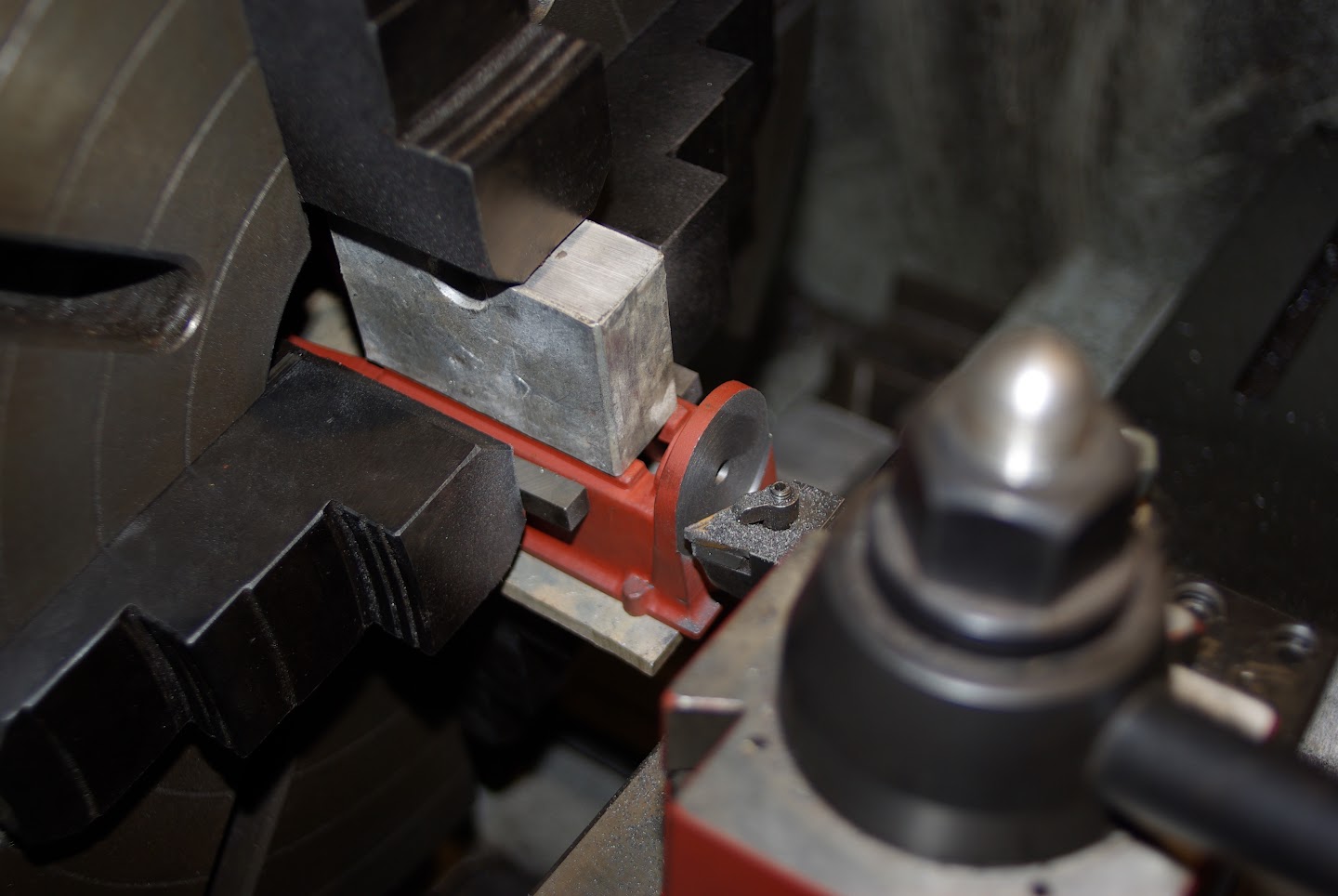
Lacking a boring head, bolt it to an angle plate, bolt angle plate to lathe face plate and turn spot face.

$188.98
TM NEXDYNAMI RE41157 Water Pump Compatible With/Replacement For/John Deere 6200 7400 6300 6600 6500 6400 7220 7600 7200 RE41157
VIVID MARKET CORPORATION

$649.00
$699.00
FoxAlien Masuter Pro CNC Router Machine, Upgraded 3-Axis Engraving All-Metal Milling Machine for Wood Acrylic MDF Nylon Carving Cutting
FoxAlien Official

$39.99
$49.99
Sunnytech Low Temperature Stirling Engine Motor Steam Heat Education Model Toy Kit For mechanical skills (LT001)
stirlingtechonline

$94.99
$109.99
AHS Woodmaster 4400 Maintenance Kit for Outdoor Wood Boiler Treatment
Alternative Heating & Supplies

$59.99
Sunnytech Hot Air Stirling Engine Motor Model Educational Toy Electricity Generator Colorful LED (SC001)
stirlingtechonline
![DreamPlan Home Design and Landscaping Software Free for Windows [PC Download]](https://m.media-amazon.com/images/I/51kvZH2dVLL._SL500_.jpg)
$0.00
DreamPlan Home Design and Landscaping Software Free for Windows [PC Download]
Amazon.com Services LLC

$160.35 ($1.43 / oz)
Replacement Combustion Chamber Kit, Burnham V8 and V8H, 1-6 Sec, 108136-01, 1129
Plumbing Planet

$40.02
$49.99
Becker CAD 12 3D - professional CAD software for 2D + 3D design and modelling - for 3 PCs - 100% compatible with AutoCAD
momox Shop

$109.99
AmTech300 - Boiler Treatment Professional Strength (Rust Inhibitor For Outdoor Wood Boilers)
Alternative Heating & Supplies

$99.99
AHS Outdoor Wood Boiler Yearly Maintenance Kit with Water Treatment - ProTech 300 & Test Kit
Alternative Heating & Supplies

$443.98
TM NEXDYNAMI AT29618 Water Pump Compatible With/Replacement For John Deere 1020 1520 2020 300 301 400 401 440 440A 480 AT29618
VIVID MARKET CORPORATION

$426.53
DM14 Engine Build Kit, Metal Engine Build Model Great Metal Material for Engineer for Factory
Easoger Official
techonehundred
Well-Known Member
- Joined
- Jul 29, 2009
- Messages
- 140
- Reaction score
- 6
f350ca said:Just grab it in the four jaw .

For the PM #1, it better have a big throat. It will have to swallow about 2 1/2" to 3" diameter to clear the back of the casting.
- Joined
- Jun 4, 2008
- Messages
- 3,291
- Reaction score
- 636
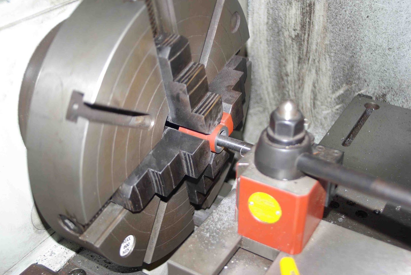
The title threw me off. Spot facing usually means facing spots in castings for individual fasteners/washers. The pic above looks like a good solution.
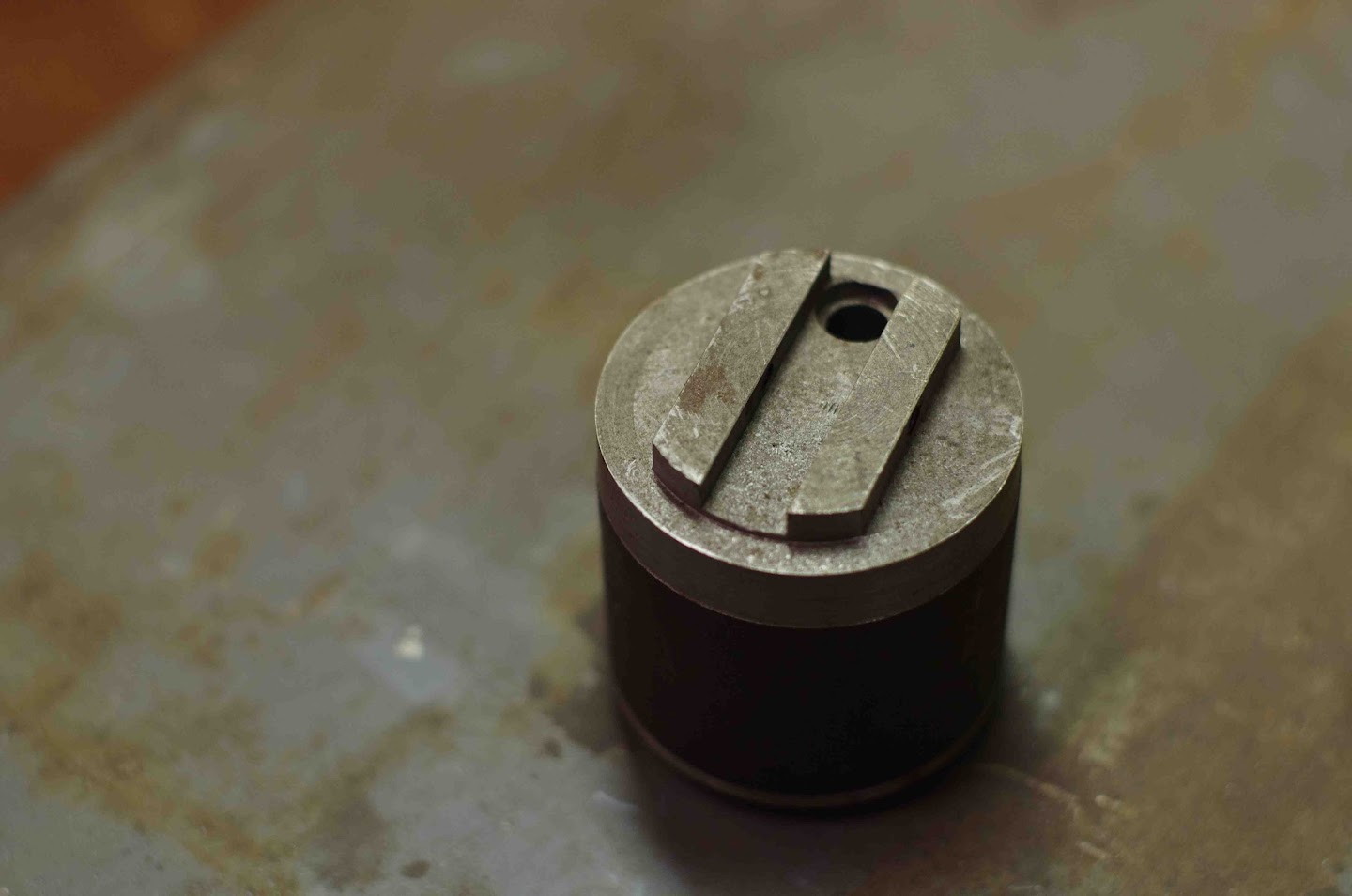
The plans that came with mine showed a neat jig for the crank, maybe they deleted it.
You turned the mains first and milled the throws to size.
The jig was a section of round shaft about 2 inch dia. You milled a slot through the center, across the face the same size as the crank throw. Then bored a hole in the slot down the length of the jig. The hole was offset from center the same as the throw on the crank or 1/2 the stroke. One of the mains went into the hole and the slot held the throw. Two small set screws came in from the side to lock the throw in the slot. The jig was then chucked in the lathe, putting the rod bearing on center.
Hope that makes some sense. Wish I'd taken a photo of it.
Greg
Similar threads
- Replies
- 17
- Views
- 3K


![MeshMagic 3D Free 3D Modeling Software [Download]](https://m.media-amazon.com/images/I/B1U+p8ewjGS._SL500_.png)


