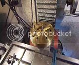
HooAwwww--Lookit them suckers go!!! I will admit to a certain amount of camera induced frenzy, causing me to call my mill a drill press, but other than that----Is this ever neat!!!


Damn Man!!! Go back and read the whole post. I've given you a verbal description. I've posted pictures. I've posted solid models!!! If you are too lazy or unwilling to read the whole post, then don't bother looking at it.---BrianI gotta say, I'm liking this alot. I'm looking forward to seeing a working model of this!
What are you going to drive with it?


![DreamPlan Home Design and Landscaping Software Free for Windows [PC Download]](https://m.media-amazon.com/images/I/51kvZH2dVLL._SL500_.jpg)


Brian,If you look at it in terms of diameters, it is a 2:1 ratio.Brian
 ), but I need to add that I could be wrong!
Brian,
I got that idea from watching the animation, - if you watch one of the legs on the spider carefully, it will move from one end of a slot to the other end of that slot (in one revolution) so that means the large wheel (slotwheel?) will have turned thru 180deg. So, 2 revs of the spider = 1 rev of the slotwheel and as far as I can see the case would be the same with with a two legged "spider" (if that's possible
Anyway, you seem to have done a sterling job!
ne scale and cut it out, then glue it to a piece of cereal box cardboard. I line up one of the non critical edges with an edge on the material which I intend to cut it from, which has been coated with layout dye and trace around the edges with my scriber. Anywhere that there is an internal radius, I use a centerpunch to punch thru the cardboard template and leave a center punch mark in the metal. Then its a trip to my vertical bandsaw, to cut the pieces out, and over to my mill drill to drill out holes at the "punch" marks. On any critical mating surfaces, I leave about .030" of material to be milled off. Anywhere that it is just a "cosmetic" surface which doesn't mate with anything, I carefully "cut to the line" with my bandsaw, and will finish those areas with a hand file..


The ratio would still be diametral, like a gear with more or less theeth, the pitch only changes.
I wonder if the "surface speed" of the outer diameter of the driven wheel will maintain constant as it goes a complete revolution. I would think that there will be slight "speed ups" and "slows down" as the rollers travel along the different angle positions on the slots. It should be interesting to watch in slow motion.
I don't think so. If you look at the typical crossed universal joint, when it's at an angle, it accelerates and decelerates twice in each revolution.Angular speed will be the same. "surface speed" or surface footage will be diametrically relative... Larger the diameter, the higher the surface footage.
Yes--Send me your "real" email address on the "private message" function and I will send you a download link to the solids models.---BrianBrain... would you be willing to send me your solids to save me a little time playing with this?


![MeshMagic 3D Free 3D Modeling Software [Download]](https://m.media-amazon.com/images/I/B1U+p8ewjGS._SL500_.png)


