Single Cylinder 4-stroke machined from bar stock - Westbury's Kiwi Mk II

Home Model Engine Machinist Forum

Help Support Home Model Engine Machinist Forum:

This site may earn a commission from merchant affiliate links, including eBay, Amazon, and others.
Kasey,

You might look into DOM steel tubing, it is supposed to be very dimensionally accurate and might make a good cylinder sleeve (not as good as cast iron :) ).

I feel silly becasue I 3D printed the crankcase, but not the cylinder, if I had I would have noticed the cylinder hole pattern didn't match the crankcase hole pattern.

Today I worked on the cylinder head, did the lathe work including the features on the bottom. I also worked on the piston, I think before I finish off the cylinder head (I still have some CAD cleanup on the finned top) I am going to make the connecting rod and piston. How cool is it going to be to see the piston go up and down in the cylinder when I spin the crankshaft?

View attachment 123024
Can you see where the head ends and the cylinder starts? Hint, look at the next photo

View attachment 123025

I have read different things regarding how tight a fit the piston is supposed to be in the cylinder, I decided to leave .005" difference between the piston OD and the cylinder ID. It falls into the cylinder and I can still get a 'pop' when I pull it out fast. I am looking forward to try my hand at piston rings. the rings will have across section of 1/16" X 1/16" and will expand into the 1" diameter cylinder.

Eccentric,
Thanks for the advice re-cylinder. I'm always looking for alternatives when making just >
research ideas into strange engines to see if its possible. and how to do it. Have just realize in my revised design of the crankcase, I could have left off 2 opposite sides and used the cylinder bases themselves alone as part of that. Would have saved weight, $$$, and time and made things more compact. I missed that on my 3d model also. I've now finished the base and flywheel mounting work and hope to set it up for a start up and a very short trial run this week . I just hope it starts. Have choked down the exhaust and throttle....don't want to risk an accidental rev up yet on the siamesed con rod design.......If ok, I'll will dismantle the engine then get to machine the cooling fins into both the head and cylinders, which will be a slow, patient job.
 
Made some rings today. I made 6 total when I need only 2 in case I break one. I turned a piece of cast iron to an OD .004” smaller than the cylinder sleeve wall and the ring ID such that the rings are .0625 thick. I used a razor blade to scribe a line on the inside of the ring, then set it down on the workbench and placed the razor blade exactly in line with the scratch I made, then tapped the back of the razor blade with a machinist’s hammer. The rings cleaved clean. Then I used the Les Stone’s method to heat treat form the rings. I splayed the gap open to .114”, a number calculated using George Trimble’s math and hung the ring and gag piece in front of a fire brick. I heated it and the brick with a torch as evenly as I could moving the torch the whole time. When the ring is a dull red it takes a set and falls off the gag piece. Ta-da. I needs to do a bit of cleanup, but they spring nicely into the cylinder.

1613430344000.png

A mess of rings

1613430388560.png


1613430528267.png

Gap test

1613430464820.png

Here you can see both ring gaps when the rings are placed inside the cylinder
 
The wife is watching the Austrailian Open, so I snuck out to the workshop and machined one more part before bed. This is the finished piston sans rings.

1613494803070.png

Looking at the conrod next, can't wait to see the piston go up and down in the cylinder :cool:
 
Last edited:
Started work on the conrod today.

1613606221949.png

I chopped off a piece of aluminum approximatly the size of a conrod and machined the bottom to shape.

1613606305024.png

Drilled the holes for the cap screws at the base.

1613606593808.png

Back to the mill to seperate the cap from the connecting rod.

1613606403110.png

Then over to the surface plate (my band saw table) to wet sand the joint between the cap and conrod.

Tap the holes in the conrod, open up the holes a tad in the cap, screw the cap on with cap screws (of course) then back to the mill.

1613606866020.png

Machine both holes slightly undersized, one attaches to the crankshaft and the other the piston (of course).

1613607015956.png

And ream to .001" over.

Now it is time to head over to the lathe and make a couple of fixture pieces. These will have a hole for a hold down screw and will be sized for a .001" clearance to just fit in the conrod holes.

1613607159018.png

These will allow me to hold the conrod down to a fixture plate, machine one side of the conrod, then flip it over and machine the other matching side, maintaining precise alignment.

1613607270638.png


I will clamp a fixture plate to the mill bed, then machine two holes to match the two holes in the conrod. I will then tap and clean them up them right on the mill bed. The holes in the fixture will remain aligned on the mill's X axis so when I flip the conrod, precise positioning is maintained.

I have to go back to the computer and work on the model a little before I am ready to finish the outside machining of the connecting rod. But this will have to wait until I trim the vines in the front yard and fix a leaky toliet tank upstair.
 
Wrapped up the machining of the connecting rod today.
1613700718574.png

Here the connecting rod is being teased out of a stick of aluminum. Machining the first side here.

1613700795502.png

Connecting rod off of the machine. It would be nice to have a bead blasting cabinet and see if I could remove the tooling marks.
 
I took the conrod over to a buddy's house and used his blasting cabinet, he had some pretty coarse media, but it really gives the conrod a nice cast appearance. I am going to do the same thing to the engine case, maybe get some walnut shell media and take a look at how that does.

1613766994952.png


I just noticed that the two precision pins I had put in the conrod to protect the internal bearing surfaces while sand blasting got pretty chewed up, and if I just pull them out they will destroy my nice internal bearing surfaces I worked so hard on. I'll carefully cut them off. Well not the main mearing, of course, I'll just take the cap off.
 
Last week I submitted a post on my techique for making fly cutters to cut gears. Today I made a second cutter, they are unique to both the pitch and how many teeth a specific gear has. Today I made a 36DP cutter for a 1" gear blank that has 36 teeth. This is the Spur gear attached to the camshaft that will, of course, mesh with pinon gear with 18 teeth on the crankshaft.


1613959995510.png

First I turn the gear blank to 1.055", then begin cutting teeth .062" deep.

1613960101716.png

Here you can see both the fly cutter and the teeth is is cutting.

1613960198832.png

The teeth cuts are almost finished.

1613960307270.png

The final result. Still need to ream the center hole and put in a keyway.

Next I will cut the pinion gear which is half the size of the spur gear. It is supposed to be steel, but I am going to cut a brass gear first, then try to cut a steel one. I don't know if the cutter will be able to handle the steel. the cutter is hardened and tempered 01 tool steel, so if I run the cutter fast and feed very slowly, it should handle the steel. Also, I will make several incrementally deepter cuts. With brass I make the cut in one go.
 
I’ve never cut a gear, but considered the “fly” cutter approach because it looked like an inexpensive way to get into the process.

I wondered about your statement regarding making multiple passes in steel, thinking that a slow feed into the material would be sufficient. Is this because of the lack of rigidity in the single tooth used in the fly cutting procedure?

Thanks in advance for any thoughts you can share!

John W
 
John,

I agree with your assesment that a slow feed would be as good as several increasingly deep passes. The thing is, when I am cutting teeth, the lathe spindle is controlled by an indexer, not the lathe motor, so since the lathe motor is not running I have to move the carriage by hand. I am not real steady on the crank and it is difficult for me to maintain a really slow and steady infeed. In fact I did attempt to make a steel pinion gear and I got about 6 of the 18 teeth made when the tip of the fly cutter fractured. It is a fine balance when tempering the cutter, too little, say a light straw and the cutter is hard, but brittle. Too much, say a dark straw, and the cutter is too soft. In my case, the cutter was too brittle and broke clean off.

The fly cutters have much less "meat" behind the cutter surface and are much less robust than, say, the commercial cutters with many cutting edges per revolotion.

Everything I know about cutting gears I learned from Chris over at Clickspring. I have only made single "flute" fly cutters. He also explains how to make a much more robust multi-flute cutters, much more like the comercial gear cutters. I may give that a try, but that is a whole other project.
 
Today I made the pinion gear and the camshaft, such as it is.

1614043616907.png

I made the pinion gear from brass rod as it is smaller and needs to be 3/8" thick. I made a first pass around the gear cutting the teeth to the theoretical depth, then took the spur gear and engaged the teeth. I measured the center to center distance (actually I measured the outside to outside distance and calculated the center to center distance) and found it to be .752” when my actual shaft distance is .750” This would have resulted in overly tight gears. So, I took another pass around the gear cutting .005" deeper. Now the gears mesh nicely.

1614043971081.png

Here is the resulting gear pair. The cams will go behind the spur gear.


I went to the metal store today and picked up some bronze and 303 stainless for the valve guides and the valves. I have a bunch of brass, but when I Googled "is brass good for valve guides" I got an emphatic answer back: "No, plain old brass would be a bad choice for valve guides. Your application (high heat, reducing atmosphere, poor lubrication, dry rubbing, heat transfer, low force reciprocation) requires a material especially suited for it."


So what does Google recommend? "Manganese bronze is ideal because it is more compatible with stainless steel. ... manganese-bronze is still the best choice for valve guides. "

Well, if Google says it, it must be true.;)

Why 303 stainless? there are perhaps harder stainless steels, but 303 has nice machinability characteristics which is important for the home machinist.
 
Today I started work on the Cams, got on a roll and didn't think to take pictures of the process. I still need to cut a keyway in the cam pair, and cut off the end piece that allowed me to chuck it in the lathe. Then case harden, temper and polish.

1614130802733.png

The cam pair will sit right here behind the spur gear on the cam shaft.
 
Made a little more progress on the cams. I cut the keyways in the camshaft, cam spur gear and the cam pair. I am using a 1/16" dowel pin as my key.

1614204072190.png

Camshaft with its keyway and key along with the spur gear and cam pair.

1614204334558.png


1614204456600.png

The pen is pointing at another 1/16" dowel pin mounted in the crankshaft, this one engages the pinion gear. I built the pinon to print, but in hindsight I would have made the collar that engages the pin larger and capture the pin. I am thinking of adding a sleeve over the crankshaft on the inboard side to cover the pin and retain it. I will cut down the pin.

1614204718467.png

Progress so far.
 
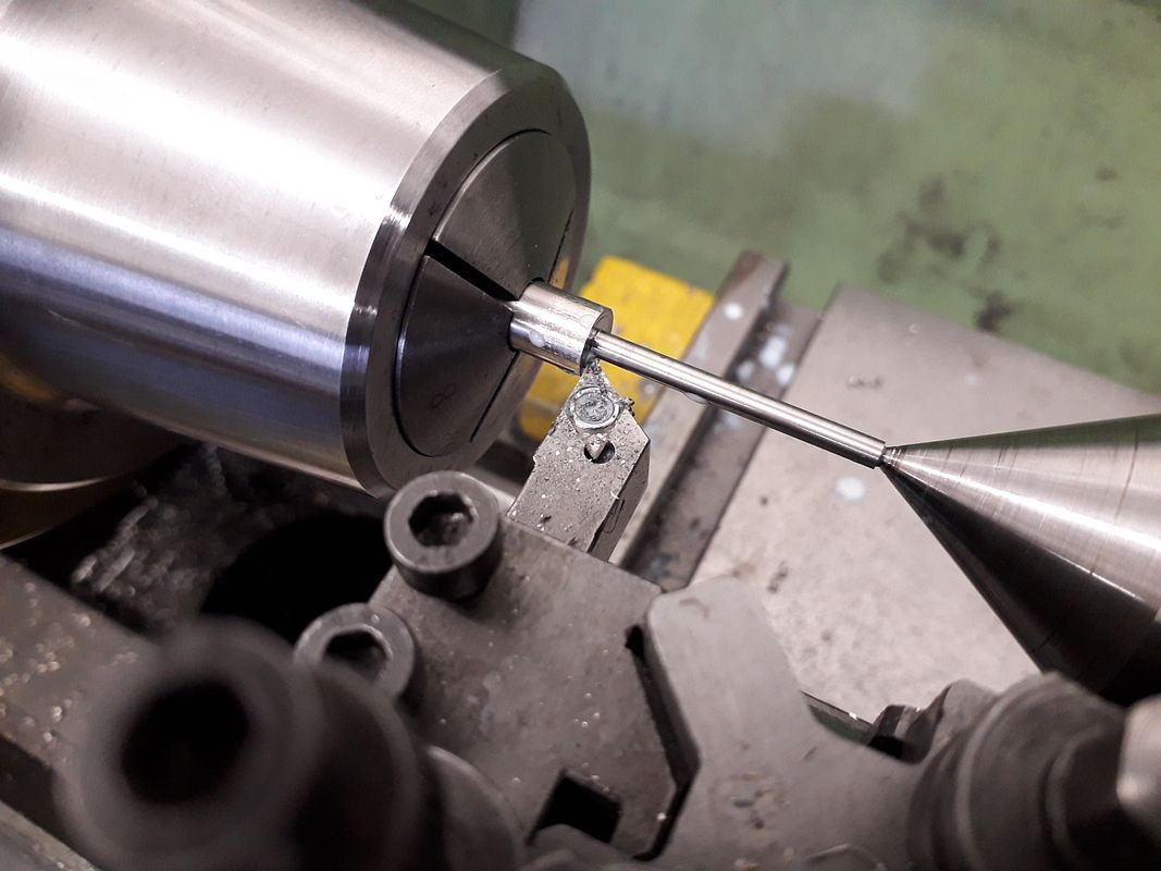
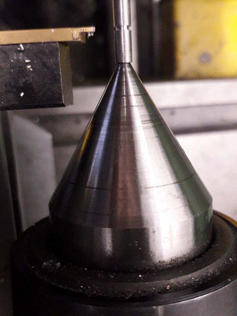
Today I thought I would show some fails. I have started work on the valves and rockers, but have not made a useable part yet. What is the saying? You usually make about three sets of parts to end up with one good engine? I have a hard time parting off steel in the lathe.

1614637988998.png


So not to end on a down note, I have also been working on the cylinder head top machining and am happy with the progress there. I still have some hand filing to perform, but the head looks to be a keeper.

1614638205058.png


Maybe I will take a break from the valves and rockers and work on the flywheel. :)
 
When machining the valve stems, machine a 1/3 to size, then the next 1/3 and then then last, a lot less flex in the stem. These were machined out of 316 ss.
Cheers
Andrew
 

Attachments

  • 19.jpg
    19.jpg
    238 KB
  • 20.jpg
    20.jpg
    274.6 KB
  • 21.jpg
    21.jpg
    133.9 KB
  • 22.jpg
    22.jpg
    148.1 KB
A couple of years ago, parting off on the lathe suddenly kind of gelled in my mind and now I hardly have any difficulty with it. (Famous last words. I probably just jinxed myself) I always part off by hand, not under CNC.

If I may add something, if you're parting the thin ends of the valve stems (the first picture looks like it), that's the wrong end. Face the end you're going to make the stem, then cut 1/3 at a time to about .003 over desired diameter. When the first third is done, cut the next third and then the final third, like Ghosty says. Get them to final size with abrasive paper. When you're done using the full diameter handles you left on, part off the finished valve from the handle.
 
Today I thought I would show some fails. I have started work on the valves and rockers, but have not made a useable part yet. What is the saying? You usually make about three sets of parts to end up with one good engine? I have a hard time parting off steel in the lathe.

View attachment 123508

So not to end on a down note, I have also been working on the cylinder head top machining and am happy with the progress there. I still have some hand filing to perform, but the head looks to be a keeper.

View attachment 123509

Maybe I will take a break from the valves and rockers and work on the flywheel. :)
On many of my critical small parts, especially valves and cast iron rings, I have taken to holding a pencil die grinder in my tool post and cutting off with a 1/16” thick dremel abrasive cutting wheel. This leaves a much cleaner surface, especially on skinny rings, and requires almost no further finishing on the face of a valve.

Additionally, when turning sub .125 diameter valve stems, I turn them in 1/3 increments down to a couple thousand of finished and then clean them up with abrasive paper to final polished dimension. This was a trick Brian Rupnow mentioned, and since I started doing that, my slim turned parts are now looking like a million bucks!

John W
 
I tend to make them slightly over length so that I can use tailstock support so the full length can be turned. Also just saw them off and then turn the end with light cuts rather than parting off. These are 3mm

20200208_094321_zpsvqlkglix.jpg

20190908_090826_zpsxxi1lj4z.jpg
 
I usually follow this blokes advice for successful outcome.

 
I have had good luck silver soldering ss heads onto drill rod of the correct size. The stem goes thru the valve head, silver soldered on both sides. Chamfer before soldering. You get a ss valve with a precision stem of strong material. The valve stem is then held in a collet and the valve head turned to size. For the final pass machining the seating surface, the side of a new insert set at the proper angle 45 degrees +/- is used cutting across the entire seat in one go, just polishing the seating surface. The finished valve can the be inserted thru the back of the collet and the stem cut to length and valve retainer grooves added.

Never had a failure. Wish I could say all my valves were leak free to start with.
 

Latest posts

Back
Top