Servo Drive For a lathe Compound

Home Model Engine Machinist Forum

Help Support Home Model Engine Machinist Forum:

This site may earn a commission from merchant affiliate links, including eBay, Amazon, and others.
Okay, another question coming from this beginner.

I went to Amazon and looked up the "Arduino For Dummies" book. What I found was around a dozen books for beginners. Do any of you have serious recommendations as to which one to buy (and which ones to avoid!) I'd like to get one but my biggest handicap is not knowing anything about what I want to learn.

Thank you.
 
You want the 2nd edition,,,,the one with the red band at the top. I think it's $22.94 from Amazon.

Be warned - Arduinos can be addictive!

Tim
 
You want the 2nd edition,,,,the one with the red band at the top. I think it's $22.94 from Amazon.

OK, it's ordered. I also installed the Arduino IDE software on my desktop computer so I could take a look at it. I'm assuming that I can also install it on my shop laptop and transport files back and forth between them on a memory stick. I'm not a Cloud guy, I want my stuff in my grubby little hands and not floating around in some mysterious cosmos hardrive. (I've told my wife's Alexa to go pound sand a number of times!)

Without some instruction from the book I might as well be looking at the wall. I played around with BASIC on a TRS-80 Model 4 back in the 80's but that has pretty much faded from memory - maybe a good thing.

As I'm looking back through this post I started, I find it interesting how it started as a thought for powering my compound to learning about micro computer programming. Now I'm caught up in learning how to bring this full circle. Thanks guys. This is getting interesting.

So now you need to look at getting one of the Arduino micro controllers. I've gotten the basic Uno (a copy from China) and the MEGA (also a copy, and not genuine, both from eBay). These use a different USB interface chip, and so a different software driver file needs to be installed to support these. Otherwise the IDE you loaded, works as expected. If you startup the IDE, and on the file menu, select Tools:Board a list of all the different products is shown supported by your download (others can be added). Here is where you'll select the product you are using so specific code can be compiled for it.
Note the first test program I would recommend is the LED blink program. It gives that quick feedback that everything is working. And you can modify the off and on times to give you a feeling you're changing code. Most Uno boards have the LED installed on the board, I have purchased one very cheap one where this was not installed.
There are many support sites and sample programs you can find on the internet, and youtube is your friend in many channels showing different programs operation and how they work.

There are starter kits on eBay that sell the Uno, CD with software, along with jumper wires, plug circuit board, keyboard, display and other sensor boards that you can do much learning from. They are in the ~$30-60USD range.
 
Welcome to the dark side!


Ignator makes some good suggestions.

There's a tutorial series on Youtube done by Jeremy Blum that is pretty good - here's a link to #1 in the series;


Arduino is very much a hands-on programming environment, so you'll need at least a basic UNO compatible board and USB cable to get started.

The starter kits are also a good suggestion - you get everything you need to get started & it's less expensive and easier than trying to figure out which individual pieces to order. There are a gazillion of the things on Ebay & Amazon that have slightly different combinations of parts - I'd suggest picking something in the mid range that has components related to what you want to do - there are at least a couple under $30 on Amazon that include a small stepper motor & driver, for example.

Be aware that some, especially on Ebay, are shipped directly from China and can take longer to get. I almost always use Amazon & go with a product that is "fulfilled by Amazon" - they might cost a buck or two more, but delivery is more reliable.

Just my $0.02.............
 
especially on Ebay, are shipped directly from China and can take longer to get

Yes, waiting 4-6 weeks is a pain. I will check the box "Item Location" for my local country and see what the prices are. As well I always select sort: "Price + Shipping lowest first". This sometimes fails in the auctions that have a selector, and they have one item that has nothing to do with the search criterion, that is ultra cheap to get you to click and look no further down the listings.
I do check amazon as well, as you never know what they have and if the price is close enough for the needed items.

I'm working on a design to convert one of the milling machine table feeds to have a shaft encoder (with quadrature output), and enable better speed control (feed rate) along with electronic travel limits. That's why I ended up with the MEGA board as it had a much higher clock speed, as I was counting the encoder with interrupts. The biggest problem with these power feed units is the speed range on the potentiometer control is very narrow, from either no movement to too fast (maybe 1/10 of the full range). Even my Servo brand power feed has this same problem (shows how perfect the China copy is). I'm hoping to have an interface where you select the endmill cutter diameter, RPM, and number of cutting edges, and the feed rate (tooth loading) is controlled per a calculation. I never push any of my tooling, mostly dry cut, so I'm not looking to maximize, but improve some cutting speed.
 
I have not done a servo install so my knowledge is limited in that field. But I have done a stepper install on my grinder, 2 axis. One of the benefits of the stepper install, was industrial level components available used, at great prices. I also did a 2 axis dividing head and slide build, using the same type stepper components. Both are running fine after 2+ years of use.

The build was detailed in the CNC forum here.
 
OK, it's ordered. I also installed the Arduino IDE software on my desktop computer so I could take a look at it. I'm assuming that I can also install it on my shop laptop and transport files back and forth between them on a memory stick. I'm not a Cloud guy, I want my stuff in my grubby little hands and not floating around in some mysterious cosmos hardrive. (I've told my wife's Alexa to go pound sand a number of times!)
You mentioned books and in that regard I have a couple of suggestions that are not directly Arduino related. One would be to look for a good C++ text, but be aware that the Arduino environment is not a complete C++ installation. While it is dated at this point in time Accelerated C++ by Barbara Moo and some other guy (past 50 here) is a good way to grab some of the basics of C++. I wouildn't even want to guess at what is a good Arduino text, to be perfectly honest the Arduino web site is actually very good with getting started materials.

Assuming you have a decent computer / OS you can get up to speed with general programming by writing code for your computer. Most Linux based distributions come with just about all the programming tools you might want. It takes a lot more work to get a decent and flexible programming environment up in Windows.
Without some instruction from the book I might as well be looking at the wall. I played around with BASIC on a TRS-80 Model 4 back in the 80's but that has pretty much faded from memory - maybe a good thing.
My first computer was a VIC 20, needless to say nothing learned there is of any value these days. In some ways the Arduino Mega chip is more powerful that those old machines. If you buy into the more recent ARM based Arduino boards you will effectively have far more performance at your disposal. The ARM based boards are will worth considering as 32 bit integers make for very easy programming and are very desirable for machine control. All that being said you don't need much at all for a compound drive.

Which brings up another point there are other embedded solutions out there. PIC mirco controllers are still popular, Texas Instruments has some interesting embedded solutions and so do others. Arduino though has a massive following so help is everywhere.

As for BASIC programming I would suggest staying as far as possible away from that language. There are micro controllers supporting BASIC in various ways but to put it bluntly BASIC is too evil to consider these days. I'd opt for Assembly before considering BASIC.

However interpreted languages have some really significant advantages but there are modern approaches that are far better. One example is Python for desktop solutions and Micro Python for embedded uses. In the Linux/UNIX world Python and similar languages are referred to as scripting languages. Python, in the form of Micro Python is one of the few that run embedded on micro controllers. In any event I just wnated to point out an alternative to C++ or BASIC.
As I'm looking back through this post I started, I find it interesting how it started as a thought for powering my compound to learning about micro computer programming. Now I'm caught up in learning how to bring this full circle. Thanks guys. This is getting interesting.

Programming is one of those skills that develops and is maintained with use. It will take awhile to get into the swing of things. My best suggestion is to get started right away with C++ on your PC writing short programs simply to learn.

By the way you don't have to go digital is all you want to do is to fed the compound at smooth rate. Digital just gives you the ability to do fancy things with the compound easier.
 
I have not done a servo install so my knowledge is limited in that field. But I have done a stepper install on my grinder, 2 axis. One of the benefits of the stepper install, was industrial level components available used, at great prices. I also did a 2 axis dividing head and slide build, using the same type stepper components. Both are running fine after 2+ years of use.

The build was detailed in the CNC forum here.
I looked up your post from 2 years ago.
https://www.homemodelenginemachinist.com/threads/conversion-of-grinder-cnc.26329/#post-288472
I was hoping this was a solution for an all manual machine conversion.
I want to do similar on a small 6x12 harbor freight machine I've had for over 25 years. It is a pain to manually grind even a small part.
The vertical feed is very poor on this machine, as the method of screw backlash control was a brass component where two threads had a bolt to preload them in attempts to minimize backlash. Problem is the screw does not have a tight zero tolerance thrust bearing. I figured this out and use a half tenths indicating dial indicator to measure the feed. With a mag chuck, it's pretty easy to throw a part with too much grinding feed. I typically don't exceed one thou feed. OK, it's a cheap machine, that sorta works.
Looks like I'll have to make shaft extensions to get any stepper motor's belt drive pulley placed.
 
..................
I'm working on a design to convert one of the milling machine table feeds to have a shaft encoder (with quadrature output), and enable better speed control (feed rate) along with electronic travel limits. That's why I ended up with the MEGA board as it had a much higher clock speed, as I was counting the encoder with interrupts. The biggest problem with these power feed units is the speed range on the potentiometer control is very narrow, from either no movement to too fast (maybe 1/10 of the full range). Even my Servo brand power feed has this same problem (shows how perfect the China copy is). I'm hoping to have an interface where you select the endmill cutter diameter, RPM, and number of cutting edges, and the feed rate (tooth loading) is controlled per a calculation. I never push any of my tooling, mostly dry cut, so I'm not looking to maximize, but improve some cutting speed.

Yes, the mega board has some additional capabilities that are really useful, more I/O pins and multiple serial ports can come in handy. I just ordered one for another project on my list.....

For the speed control sensitivity there are a couple solutions:
1. Putting a resistor in series with the pot will reduce the adjustment range and give you more sensitivity
2. Replacing your standard 270 degree potentiometer with a 10-turn pot will give you full range adjustment with about 12 times the sensitivity......

Tim
 
For the speed control sensitivity there are a couple solutions:
1. Putting a resistor in series with the pot will reduce the adjustment range and give you more sensitivity
2. Replacing your standard 270 degree potentiometer with a 10-turn pot will give you full range adjustment with about 12 times the sensitivity......
Tim, I don't believe that solution will work, as the circuit is a half wave SCR triggered design. SCRs are triggered with injection of gate current, that is positive relative to the Cathode. A resistor may modify this, but a design change that controls the current pulse to fire the SCR is needed. These power feeds are minimal designs.
I scanned the schematic that was included in the Align brand manual;
upload_2019-1-26_17-24-37.png

It is a very smudged original copy. The SCR is in series with the motor armature. The field windings are shown as "L". The SCR part number is S6008L, so it's a 600V 8amp TO220 device.
I had taken a photo of the board as part of my project (still in limbo with other things of higher priority);

The schematic shows ZNR, they are MOVs. There is an adjustment pot on the board labeled as SVR-100, which is 100ohms. The speed pot is off board, and shown as VR-500.
Given this is a half wave speed control, that really limits the torque during low speed operation.
 
Tim, I don't believe that solution will work, as the circuit is a half wave SCR triggered design. SCRs are triggered with injection of gate current, that is positive relative to the Cathode. A resistor may modify this, but a design change that controls the current pulse to fire the SCR is needed. These power feeds are minimal designs.
........
Yeah, that's a pretty minimal design all right. The MOV's are part of a snubber circuit to suppress any spikes or back emf. A better design would be one with two SCR's and diodes, or a triac, again with suitable snubber circuitry.

I still think the 10 turn pot used with the original circuit might get you enough sensitivity of adjustment.......easy & inexpensive experiment.......

Tim
 
For what its worth my rotary table controller here also has a linear mode and you can store different configs so the one controller could be used on the tailstock and a rotary table and as a milling power feed just by selecting a different device.

https://www.homemodelenginemachinist.com/threads/interrupt-driven-rotary-table-controller.25091/
Even if you do build your own, the code would be a good tutorial on C.

I did think of powering the tailstock on my AL336 lathe as I did a lot of repetitive drilling that was affecting my shoulder. But I sold the lathe, purchased another larger one and outsourced the said parts. I would have used a NEMA23 269 Oz stepper and a reduction belt drive of about 3:1 or 5:1. Remember, there is also a reduction on the acme thread. I've got a couple of 24 volt electromagnetic clutches here that came out of old photocopiers that could be used to free the drive for manual operation. Once power is applied, they lock solid and are completely free when powerd off. You can buy the clutches on alibaba. Programming a simple peck drilling cycle would be a good feature to add.
 
For what its worth my rotary table controller here also has a linear mode and you can store different configs so the one controller could be used on the tailstock and a rotary table and as a milling power feed just by selecting a different device.

Again, it looks like I walked into a very interesting sideline to this machining hobby. This idea of a dual use controller got my attention.

I'm in the reading mode with this project now. I've also taken apart my 8" rotary table to clean and oil it while checking out how I would mount a stepper motor on it. I've moved away from the idea of a compound power feed (for now). There seems to be a whole lot more information on rotary table projects so I will start there.

First I have to get the proper hardware so I can have a test bed for learning the electronics. The table rotates very smoothly and freely and looking at the mounting possibilities I'm thinking of a NEMA 23 motor without any extra gearing. The idea of having both manual and powered capabilities makes sense to me so the idea of a dual shaft motor installed on the table with the hand crank in the outboard position seems like a good plan. The mounting pieces for this will make for a good machining project. That's where I start to come up short.

When searching Ebay for a motor I see many different Nema 23 types. First, I'm drawn to the ones with a cord rather than the ones with loose wires - obvious protection and easy connect/disconnect. Second, what voltage do I look for? I'm seeing everything from 3 volts to 24-48 volt motors. I understand that the power supply and the controller have to be matched to it and I lean toward the higher voltages. I'm assuming that the voltage is varied to vary the speed? (I'm more familiar with variable frequency drives on AC motors.) I suppose this should be a common sense answer but treat me as a pure novice. Does the power supply provide one set voltage and the controller (via the Arduino program) vary it to provide speed changes?

The table that I have is 90:1 and I'm not sure how this determines the particular motor specs that I require. (Remember, I come from a world where I'm used to buying a 25 hp. 480 volt 3-phase motor and just getting a VFD that's sized for it.)

Then there is the question of feed speeds for making smooth cuts and traversing speeds for positioning individual machining cuts - this is Arduino stuff, right?

I'm not going to buy the Arduino supplies until I have something to power with it and I would rather not buy 'any-old' motor just to play. I want the equipment that I will be using for my project.
 
I'm assuming that the voltage is varied to vary the speed? (I'm more familiar with variable frequency drives on AC motors.) I suppose this should be a common sense answer but treat me as a pure novice. Does the power supply provide one set voltage and the controller (via the Arduino program) vary it to provide speed changes?
It does not work that way (speed control). A stepper motor has magnetic poles, and the rotor is moved in discrete angular steps. The speed is controlled by how fast the field winding is pulsed. The rotor in stepper motors is a permanent magnet. A quick search will bring up all the tutorial you want;
https://en.wikipedia.org/wiki/Stepper_motor
Never open a stepper motor and pull the rotor out of the stator, this will damage the magnetic strength (the photo in the wiki article has one opened, bad example). They use "keepers" to assemble them and do maintenance. But You should never have to worry about opening one up.
Do note that unpowered the stepper motor will have a cogging feel when rotating the shaft. And it will force the shaft to rest in one of these cogged locations, so you can't just put the shaft at any angular location.
The stepper specifications will indicate the number of cogs per revolution, so unless a micro stepper controller is used, you will live with these discrete angular positions.
 
The speed is controlled by how fast the field winding is pulsed.

Thank you. Interesting, and now it makes more sense. This helps explain how they can hold a position with power on and not burn up.

But I'm still confused about selection. ->(from Wikipedia) Stepper motors' nameplates typically give only the winding current and occasionally the voltage and winding resistance. The rated voltage will produce the rated winding current at DC: but this is mostly a meaningless rating, as all modern drivers are current limiting and the drive voltages greatly exceed the motor rated voltage.

How the heck do I determine which motor to buy? Flashing back, again, you use a 240 volt motor on a 240 volt circuit and a 480 volt motor on a 480 volt circuit. How do you spec a motor, and a power supply, of this type? How do I know what goes with what?
 
Now I'm dreaming ahead about if (?) I can get a rotary table to work then the (original) idea of a powered compound and a powered tailstock would be fun additions to the lathe, too
 
The stepper motor requires a stepper driver. The motor volt rating determines the power supply voltage that you connect to this stepper driver. This will limit the coil current to the motor designed max. But per your quoted wiki, you can set the motor current with the stepper driver that has this design feature. It is programmable with DIP switche 1-2-4-8 binary setting or straps. This ensures that the winding's don't melt down. You may use a higher voltage then needed, but this is mainly to be able to run the motor at a faster speed, when this is important. You can exceed the stepping pulse rate, faster then the motor rotor can respond. This results in lost steps and that is a bad thing if you are driving a rotary table, and expect an exact angular change. This should not be a problem in your usage, as home hobbyist's aren't trying to remove material at maximum rate (at least not me, as tooling is on my nickle, and I dry cut).
 
Its all pretty simple to get a stepper running. But there are a few parts to it.
1. A step generator (eg Arduino)
2. A stepper controller. I use this http://rover.ebay.com/rover/1/711-5...0001&campid=5338413729&icep_item=271115223142
3. a 5v supply to run the step and direction interface (perfect for an Arduino)
4. a 48 volt power supply with enough amps to match your stepper motor requirements
5. A stepper motor. These have standard frame sizes so a NEMA23 is perfect for this. 269 oz/inch torque is a good size.

Another alternative stepper controller is the Gecko G251x which is nice and compact.
https://www.geckodrive.com/g251x-digital-stepper-drive.html

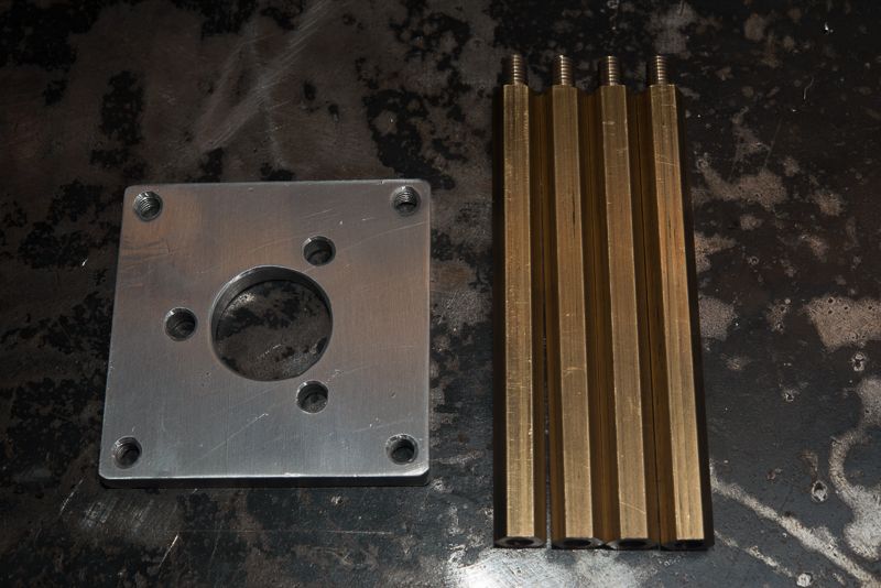
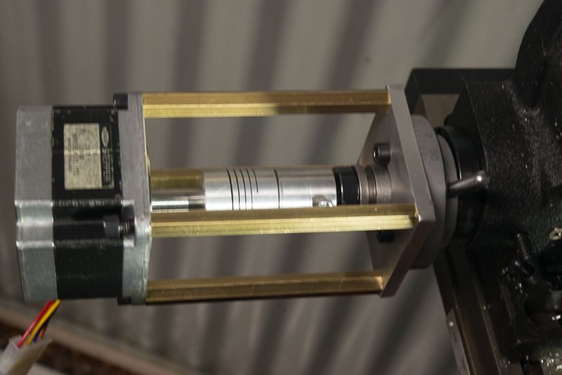
Mounting is pretty easy. I removed the handle to expose 3 threaded holes on the mounting collar and bolted a plate to this. Then added 4 threaded posts long enough to get the stepper far enough away to accommodate a shaft joiner. You should be ale to use a solid joiner there as the threaded rods allow adjustment to get perfect shaft alignment.
DSC_5245_zpsaff064cc.jpg


DSC_5246_zps413f139b.jpg


This was a surplus NEMA23 stepper motor. It does the job with no missed steps on my 6" table but I'd go one that has a longer motor frame and more torque.

But be warned, its addictive and has probably cost me $10k building a bigger CNC machine!
 
Back
Top