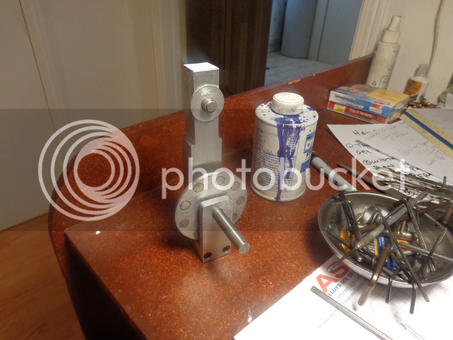
Rpm indicator

Home Model Engine Machinist Forum

Help Support Home Model Engine Machinist Forum:

This site may earn a commission from merchant affiliate links, including eBay, Amazon, and others.
This thing is evolving as it develops. I have decided that to really work in a balanced manner, I need the pointer plates to extend down on both sides of the magnet disc. I am going to call around today and see about getting the two strange shaped outer pointer plates water jet cut. I'm not going to break the bank, but they are rather miserable shapes to cut.
 
Love it. I'm following Brian.

I like old-school mechanical instruments because they quiver and make everything say: "I'm alive!" Just another reason why I also like old cars and whatever else has an engine or lots of visible mechanical parts.

(In an attempt at humor, I say:) So I can see your little power plant with the tach and a voltmeter and whatever else you can cook up with a few late-night inspirations and only a few days to build.....

Keep 'Em Coming,

--ShopShoe
 
So, we are all ready for a test drive except for the pointer. I called the local water jet guy, and he said there was a minimum $150 set up charge. I explained that I would have to sell my youngest grand child to come up with that kind of money for a something that was basically a toy. When he asked what I meant by "a toy", he seemed very interested and told me to "Send a .dxf file over anyways, we MIGHT have a run of 3/16" plate going through today on a big job". Wink Wink/nudge-nudge. So---I sent him of a dxf file of the pointer. Who Knows??
 
Let's call the force or better the torque pulling the pendulum to the left positive, and the torque pulling to the right negative.

If you could visualize and plot the torque versus time it would look like a sinusoid with equal positive and negative peaks, equal positive and negative areas under the curve and therefore zero average value.

Turning slowly the pendulum will have time to follow the attraction left and the attraction to the right. As the speed goes up, the inertia of the pendulum "filters" out the oscillations, it is sensitive only to the average torque and stands still.
 
It would work but you might have
to use a spring to bring it back to Zero

Once Brian gets it working by using a different operating principle, he can use the weight of the arm instead of a spring, although far from linear.
Instrument like ammeters and speedometer really need a spring to be independent on gravity for obvious reasons but in this case the "instrument" orientation is fixed and is not called to be shaken like a speedometer on a bumpy road.
 
As a point of interest---I suspended a length of 3/4" square aluminum bar in much the same position as the steel bar with the slot in it. It didn't do anything at all.--Made no effort to move. If I made the hanging weight a disc of either steel or brass, the steel disc would probably counter rotate somewhat similar to a gear drive, but that wouldn't be of any use to determine rpm. Likewise, if the "Lenz" effect caused the brass disc to rotate, it couldn't serve the purpose of measuring rpm. Not all of my "Eureka" moments bear fruit.
 
As a point of interest---I suspended a length of 3/4" square aluminum bar in much the same position as the steel bar with the slot in it. It didn't do anything at all.--Made no effort to move. If I made the hanging weight a disc of either steel or brass, the steel disc would probably counter rotate somewhat similar to a gear drive, but that wouldn't be of any use to determine rpm. Likewise, if the "Lenz" effect caused the brass disc to rotate, it couldn't serve the purpose of measuring rpm. Not all of my "Eureka" moments bear fruit.

hi Brian,
I think your not getting the picture of what we are trying to explain
simply look at it a a centrifugal clutch. the more magnet you have spinning agains each other the harder it's going to be for your lever to go back to 0
then set it at "500 RPM" with your Tach and make your scale from there

cheers

Luc
 
I don't want to say I told you so (I'm not like that) but your experiment did confirm what I thought would happen.

I assume you will get some oscillation of the pointer when the forces are not in equilibrium, but I can't see how the pointer would substantially deflect in one direction

But all is not lost, you just have to work out how to fix it.
 
Brian,
What if you use the magnets to generate current via a small coil, then process the output voltage via a large capacitor and a diode. Buy or make a simple amp meter to measure the current flowing to ground through a resistor. Make your own scale in cad for the amp meter to indicate rpm.
Rich
 
Hi John,
Thanks for vendor info . ''Born Loser Gus'' bought two pcs 10 mins ago..One more for backup. Been looking for Tacho for long time. May need help to get it working. At long last ,I have a tacho to read speed of my DIY Nemett-Lynx Engine.
Gus,
The sensor with those units does have a fairly large surface area on the face, it is about 10mm diameter, so not tiny, but you could just stick a small neo magnet onto the flywheel and bring the sensor into fairly close contact and it will read the RPM.
That is why they are such a boon for machinery, very robust and on machines there is usually not a problem mounting the sensor somewhere.
BTW, the leads should have the correct plugs on the end so that it all just plugs together, and I used a cheapo voltage switchable wall wart to give me the input voltage. Just mount the bits into a small plastic case with the sensor nose sticking out of it and you will have a portable (almost) unit.

BTW, the only reason I am fitting one to my geared head lathe (with fixed speed ranges) is that soon I will be fitting a variable drive to it, and I will need to know what the speed of the spindle is.

Hope this helps

John
 
There are many way to skin a cat, making an "alternator" and then measuring the voltage with a voltmeter is one way but I think Brian was after a "direct" method like is used in the old car speedometer.

To that end I suggest studying the principle and copying the design in modified form still keeping the same operating principle.

Magnet moving next to a conductor are "dragged" back by what appears to be friction, but in reality is a magnetic effect due to induced currents, as we have seen in the video.

Basically build a wrapped up equivalent of the magnet flying next to a conductor (like the video), Instead of a single event like the fall on a linear bar the phenomenon is restarted by making the end return to the beginning by developing the device in circular form.

In other words think of a rotating motor as a linear (mag levitation style) motor wrapped around. (Usually the thinking goes the opposite way: we are explained how a linear motor is nothing but an electric motor unwrapped,)

If the conductor movement was only restrained by friction, then it would move following the magnet (dragged) but at a slower speed until an equilibrium between the pulling force proportional to the relative speed magnet-conductor and the friction force proportional to the conductor speed in a viscous medium.

By restraining the conductor with a spring the conductor disk will rotate until the spring torque contrasts the attraction. What we got is a conducting disk angle of rotation proportional to angular velocity of the spinning magnet. Add a hand pointer and a calibrated scale and you got an RPM meter with no wires, coils or fancy electronic.

Construction note:
A cylindrical magnet generates a flux exiting from the N and returning to the S trough the air. The permeability of air is thousands of times smaller that Iron, therefore by placing the magnet in a closed circuit made of Iron, leaving only a small gap of air will increase the flux intensity 100 folds. That is the idea behind forming magnets into a horseshoe shape.
 
I am not going to pursue this idea any farther. I have decided that if I truly wanted a mechanical rpm indicator, it could be easily accomplished with my 3 ball governor and a pointer attached to the lever arm. Depending on centrifugal force and the strength of the return spring it would be quite repeatable after initial calibration. I am semi busy with some engineering design work at the moment, so I probably will not do any more work on this thread.---Brian
 
  • Like
Reactions: gus
I am not going to pursue this idea any farther. I have decided that if I truly wanted a mechanical rpm indicator, it could be easily accomplished with my 3 ball governor and a pointer attached to the lever arm. Depending on centrifugal force and the strength of the return spring it would be quite repeatable after initial calibration. I am semi busy with some engineering design work at the moment, so I probably will not do any more work on this thread.---Brian

so,it's a fail ??
 
Gus,
The sensor with those units does have a fairly large surface area on the face, it is about 10mm diameter, so not tiny, but you could just stick a small neo magnet onto the flywheel and bring the sensor into fairly close contact and it will read the RPM.
That is why they are such a boon for machinery, very robust and on machines there is usually not a problem mounting the sensor somewhere.
BTW, the leads should have the correct plugs on the end so that it all just plugs together, and I used a cheapo voltage switchable wall wart to give me the input voltage. Just mount the bits into a small plastic case with the sensor nose sticking out of it and you will have a portable (almost) unit.

BTW, the only reason I am fitting one to my geared head lathe (with fixed speed ranges) is that soon I will be fitting a variable drive to it, and I will need to know what the speed of the spindle is.

Hope this helps

John

Hi John,

Thanks.With your expert advice Gus don't have to run around chasing his tail or re-invent the wheel. Will be fun getting it going and using it to read speed on my DIY Engines. Will DIY a wooden case to house new DIY Toy. Now waiting for kit to arrive from HongKong. Ordered place with UK and shipped from HK.
Back in the 60s ,it will take at least 3 months to receive it into my hot little hands.
 
Luc--I never stop thinking of mechanical things. I don't do it intentionally. My mind just always goes there, always has, if I don`t have something else to be thinking about. I am flooded by ideas for mechanical things, especially just before I drift off to sleep or when I have just woke up. Most of the things I think of work. Some work better than others. Some work immediately. Some work after I have spent time tweaking them. And some---well, some I try and if they don`t work immediately, I`m not really interested enough in them to put very much work into them. This is one of those things. It doesn`t really interest me enough to put any more effort into it. If somebody else wanted to take the idea and run with it, that would be great, but I won`t spend any more time on this one.---I think.
 

Latest posts

Back
Top