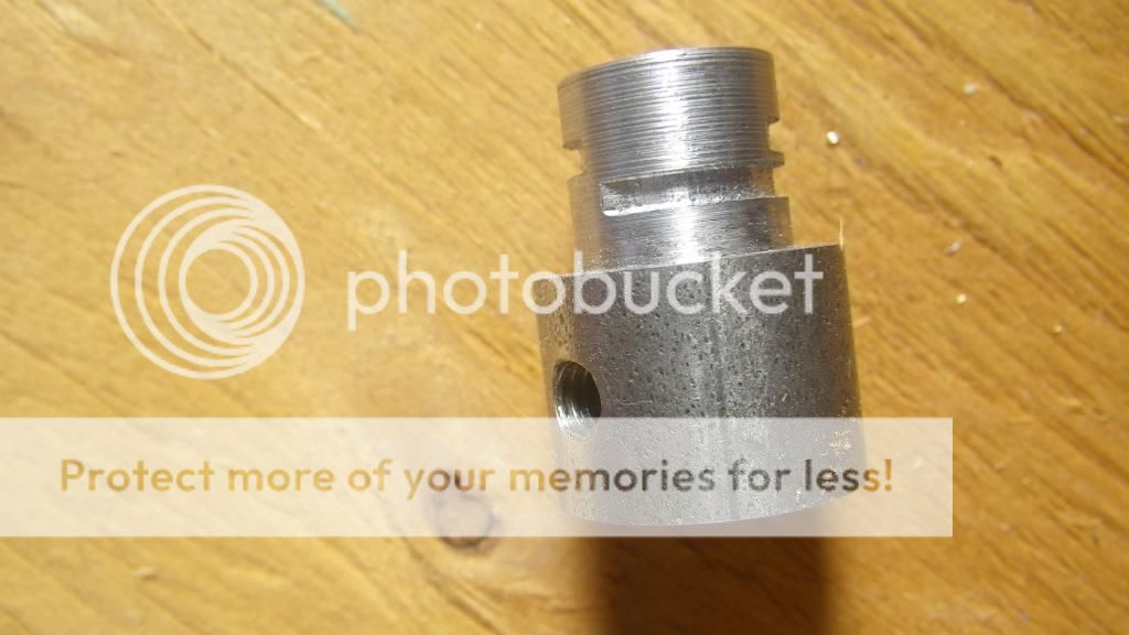
Canadianhorsepower, the valve I'm talking about is set between the pillow bearings with the hex screw in it. WCPenny, I appreciate the article. There was some decent info in there. It was a bit of a weird read as it seemed to jump sections everytime a column was over. They used a rotary table with indexing attachment and offered using a hacksaw and knife edge file as a substitute. I don't have the table and I'd rather use power tools lol. So here's my end result.
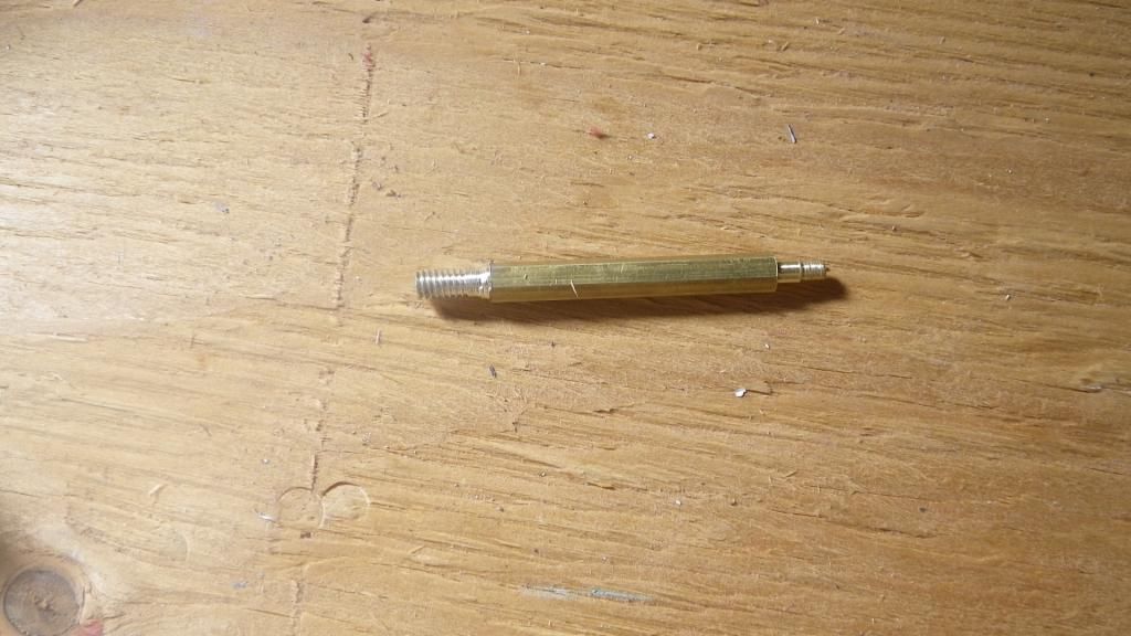
A piece of brass hex rod that I messed up earlier in the project used as leverage to pivot the valve.
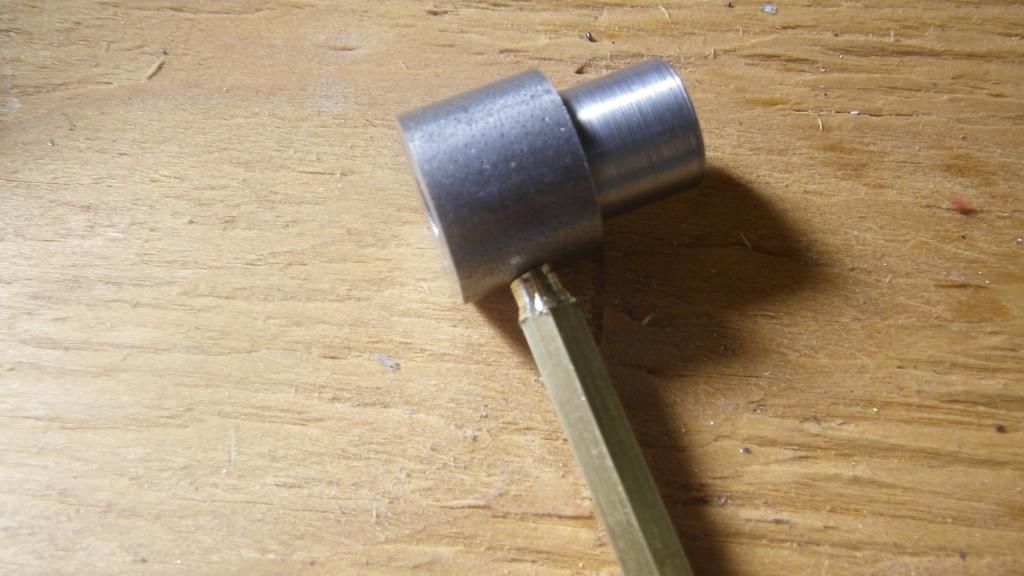
The rod screwed into the locknut hole on the valve
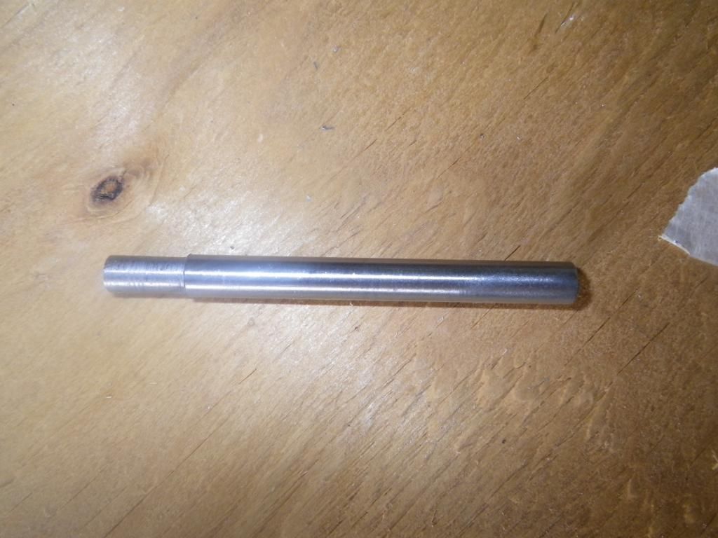
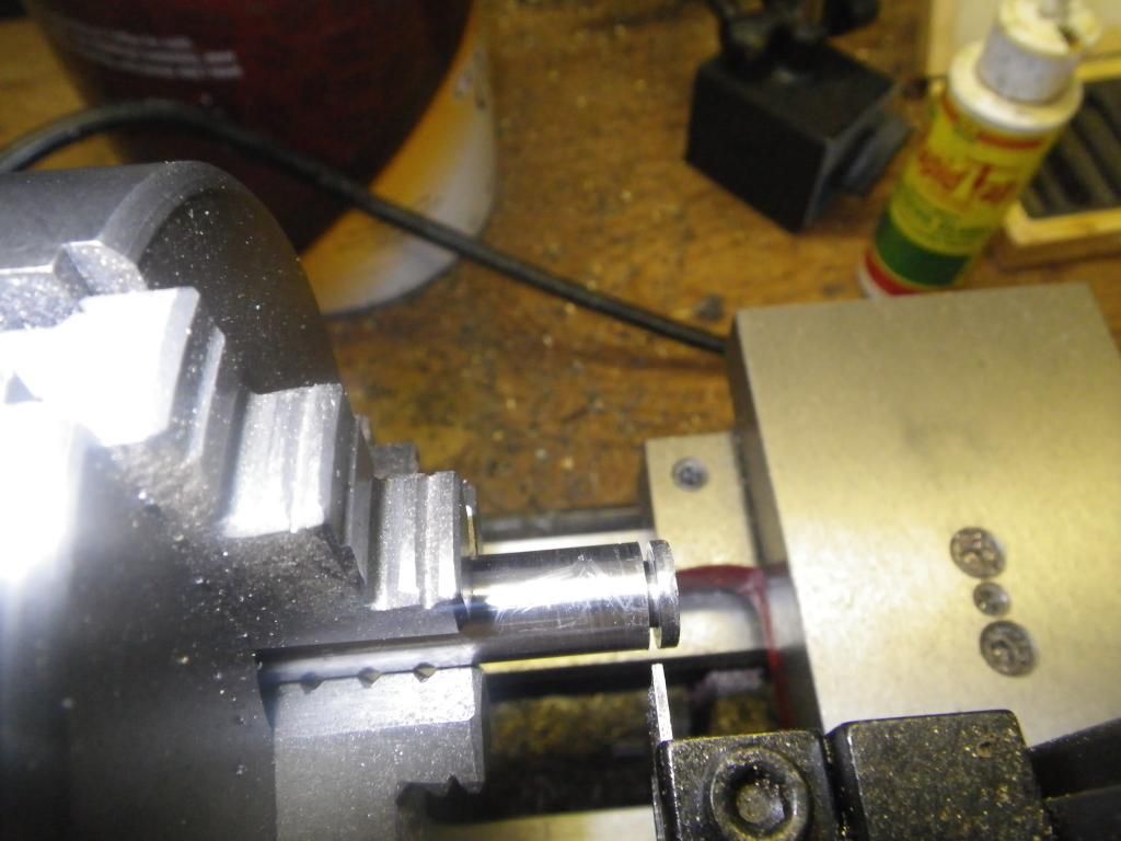
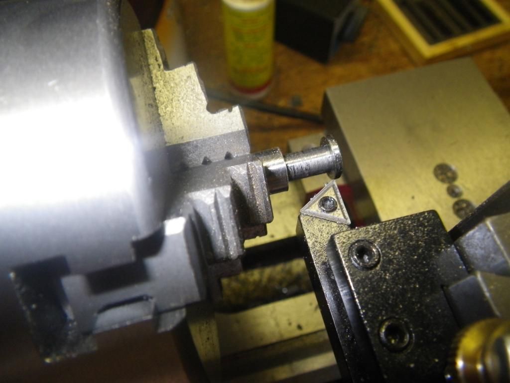
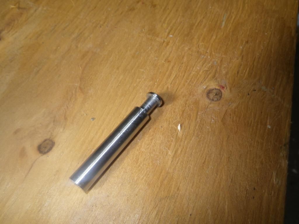
A piece of .250 drill rod machined at the end to fit tightly inside of the valve
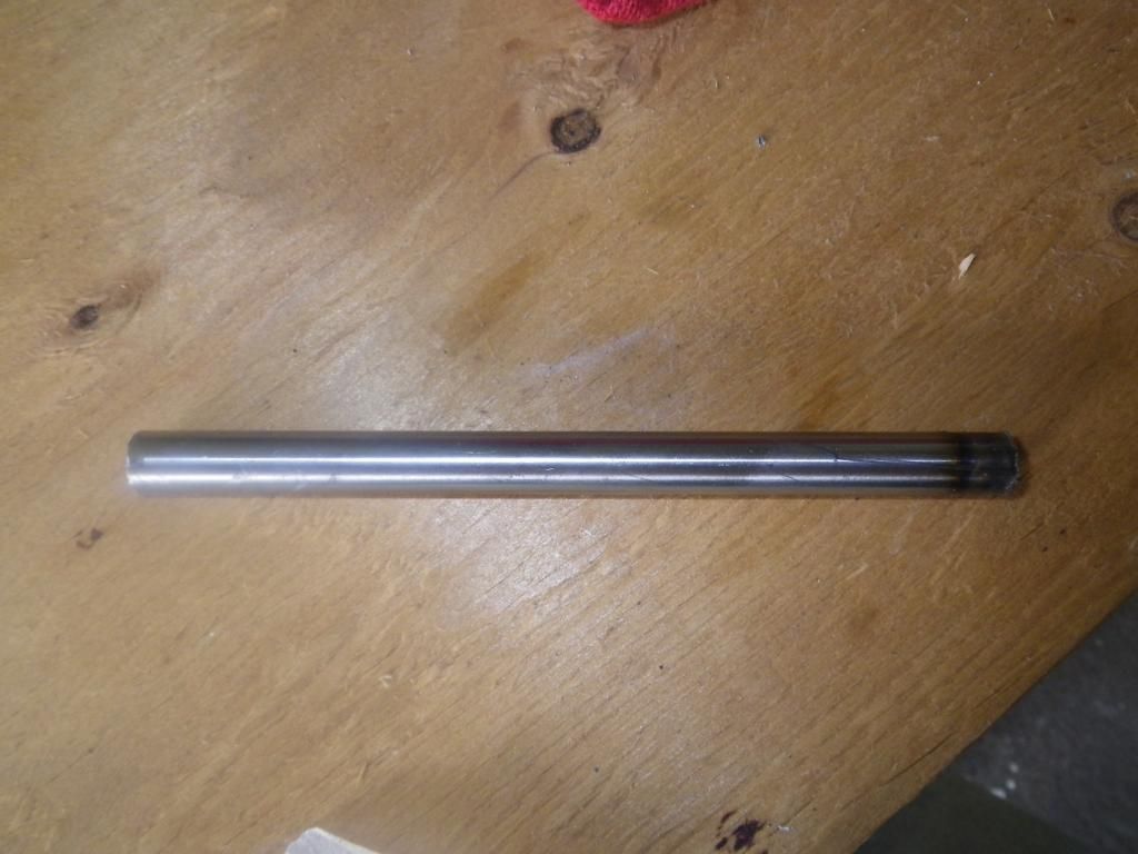
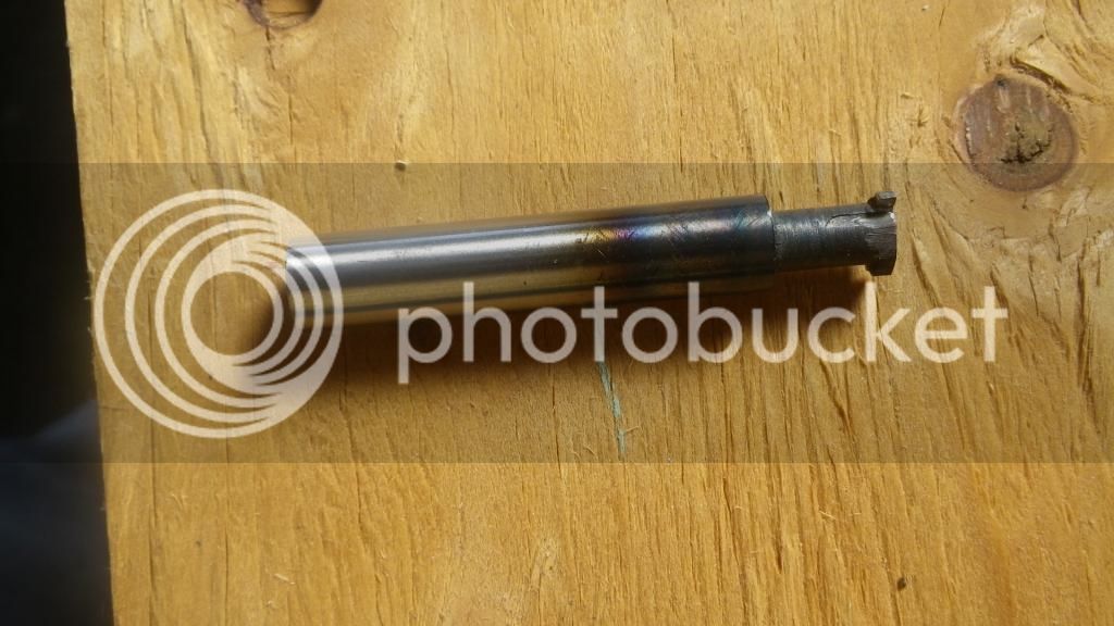
The .375 drill rod soon to be my cutting tool
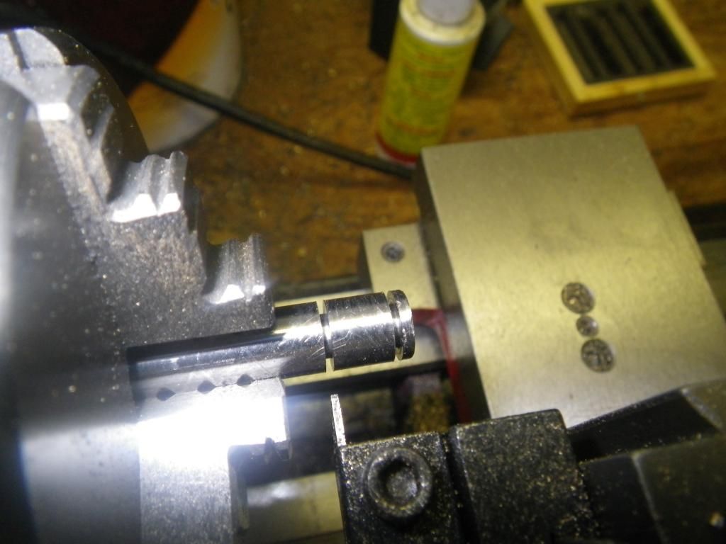
Parting the drill rod to the with of my valves and to clear the top of the valve.
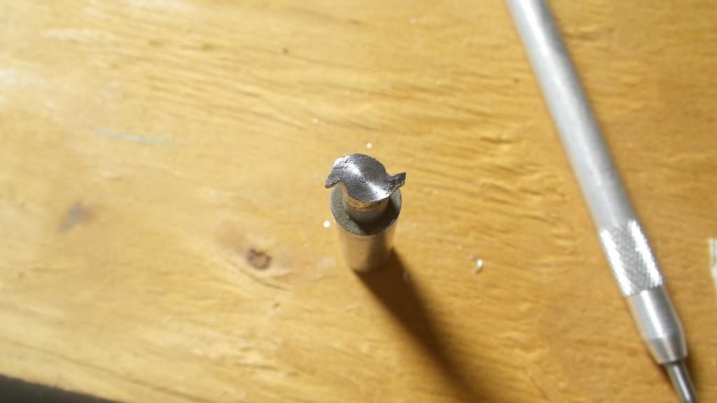
Ready to start putting some teeth in it.
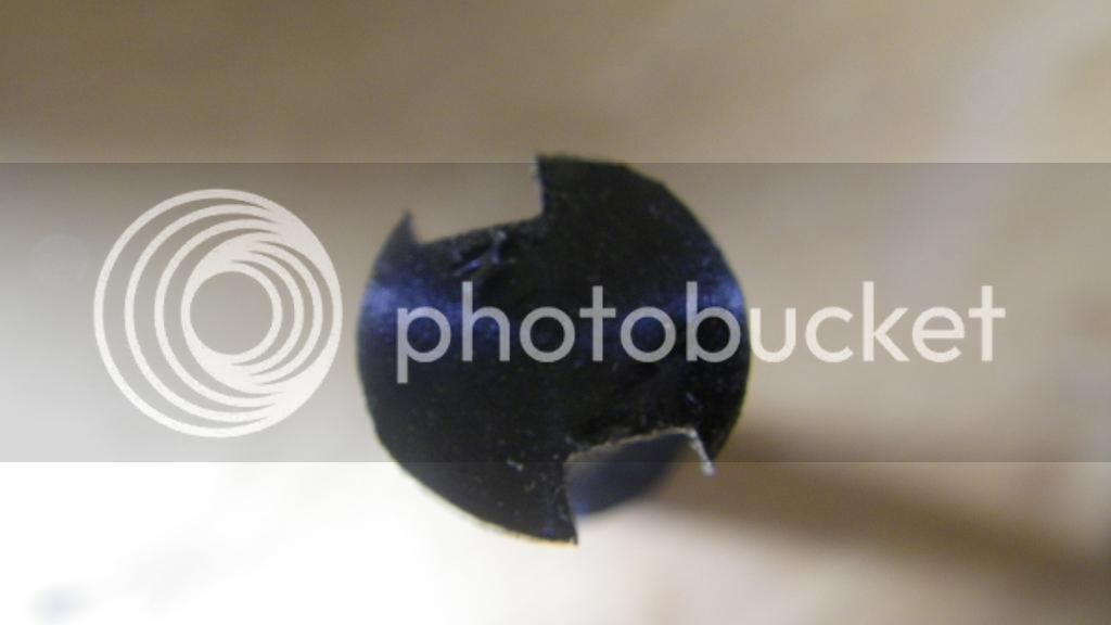
Roughed the teeth with a 1/8 endmill
Finished the teeth with a cutoff disc and a dremel.
Hardened the teeth
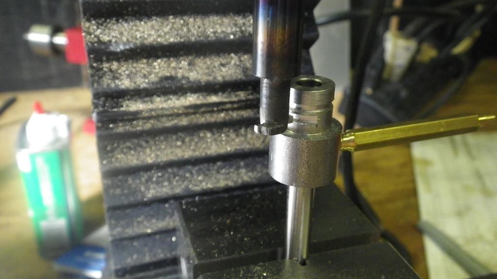
Turned the valve by hand in the mill. In hind sight I should have drilled and tapped the pivot for a small bolt to provide downward force as it was a chore to keep it from jumping around, but whatever, it worked lol.
Used a needle file to clean the burrs and voila, a rotary valve!
I'm sure that most of y'all have ran into and tackled much more complex and difficult problems especially you guys that have been doing this for years. But for my second machine project, I'm quite impressed with and proud of myself

Thanks for your help though!


