Reducing Mini-Mill Column Flex (and Column Y-Axis Alignment)

Home Model Engine Machinist Forum

Help Support Home Model Engine Machinist Forum:

This site may earn a commission from merchant affiliate links, including eBay, Amazon, and others.
Finished my back plate today(120mm wide 300mm high 12mm thick), had to mill the surface that is in contact with the back of the column. Not the best finish but at least its flatter than it was to start with.
Snapped a drill bit drilling one of the holes! which has cost me a few end mills trying to get the bugger out!
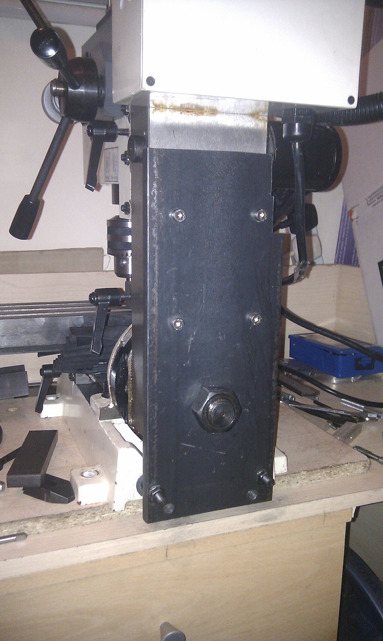
IMAG0265.jpg

Didnt make a brace bar like some of you did, as you can see i drilled my first set of holes in the wrong place! I used some M8 threaded studding, put a washer and nut in between the back plate and base. Tightened this nut up against the base, then tightened the nuts that pull the back plate back in in equal increments.
The holes in the steel plate that the M8 studs go through, i drilled 1mm larger so i've got so play for adjustment when tramming.
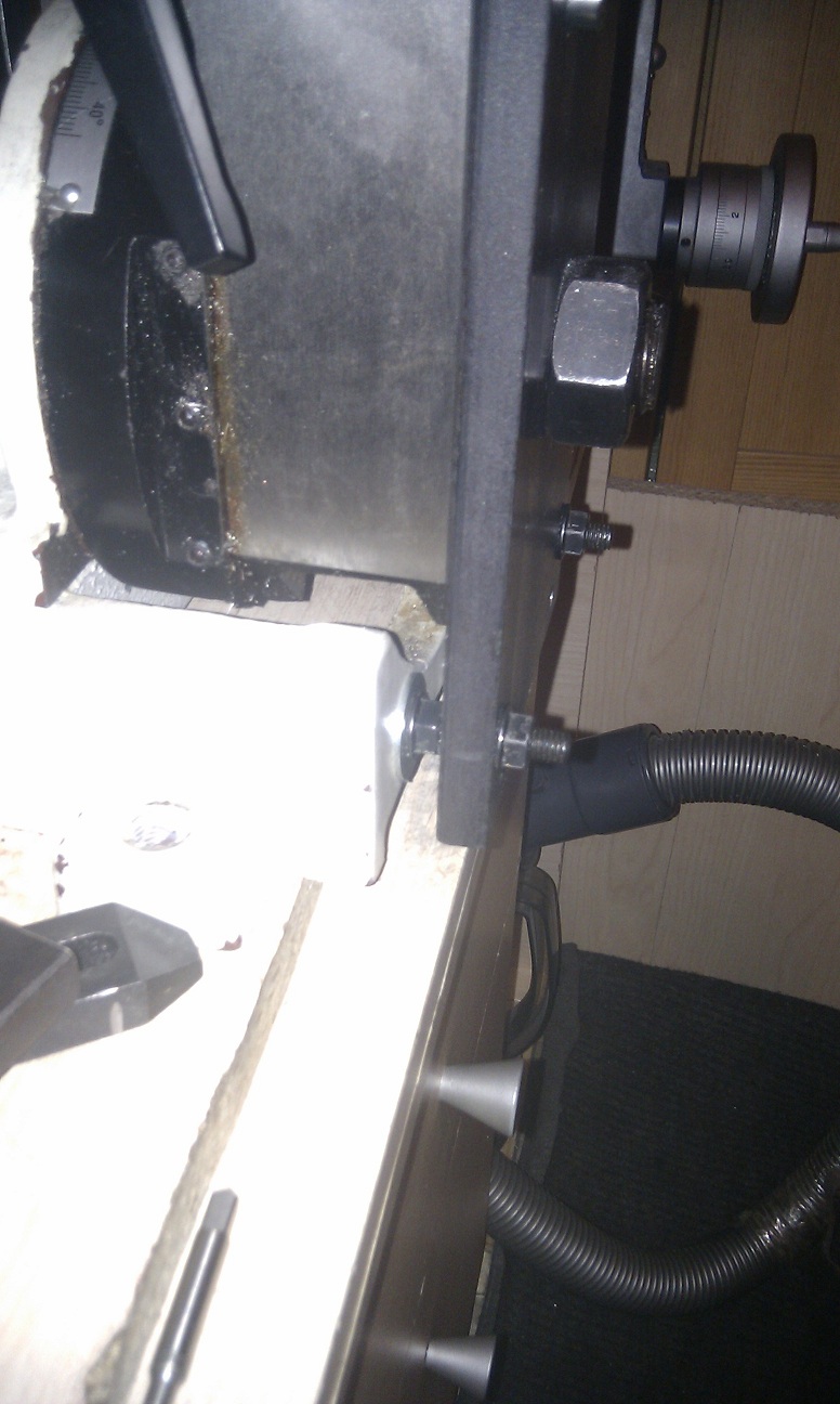
IMAG0266.jpg


Thanks for the ideas guys, just need to tram it and maybe shim it for the y axis.

edit:
Turned the nuts around inbetween the backplate and base. nip up the outside ones equally and then tighten the inside nuts up nice and tight, then tighten the outside ones up again.

should i use the bottom nuts to adjust the Y tram? Or should i just shim the spindle housing if needs be?
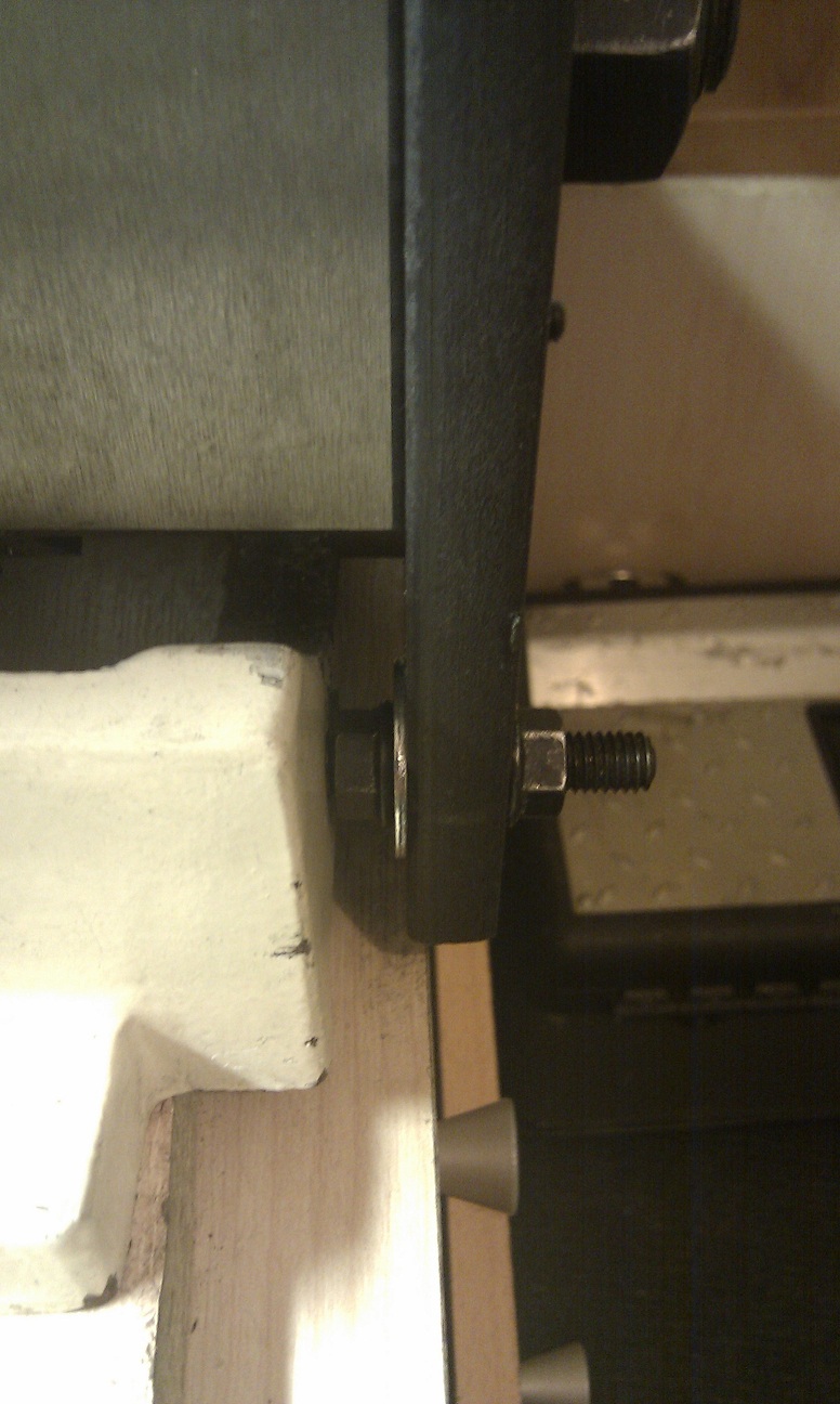
IMAG0267.jpg
 
Ok, I'm confused..
Put a DTI on a holder in the chuck swang it round so it was on the right side front of the table. Took the reading, swung it round to the left side front of the table. Carried on and moved the column untill they both matched left and right. So X axis is trammed and is only out by 0.01mm, I'm happy with that.
So then i swung the dti to the right side back of the table, its out by 0.014mm compared to the front. Roughly the same on both sides..
So my table is higher at the front compared to the back of the table in relation to the spindle. (Forward tilt)
So if i tighten the nuts at the bottom on the steel plate to pull the colomn in and in theory level the head to the table...so tighten it so that i move the DTI 0.07mm.
Measure the front of the table and rear, still out by 0.14mm ???
 
Goldigger, sorry for missing your last posts. I've been away from the computer for a few days. Nice job on the back plate. Like you, I use the bottom bolts of my mod to adjust the Y-axis tram. Sorry if you're still having problems getting your Y-axis trammed. Here is my understanding of the tramming situation when using the bolts at the bottom of the back plate. It's a bit hard for me to describe, others probably could do better.

As you adjust the nuts and bolts at the bottom of that back plate to tilt the column forward or back in the Y-direction, the column's pivot point is not at the center of the spindle. It's somewhere between the back of the column and table, and when you change the tilt of the column, you change the overall distance from the spindle to the table, both front and back. So when you tighten those nuts at the bottom of the column, the measurement from the spindle to the back of the table will change, but the measurement from the spindle to the front of the table will change too, in the same direction, but not quite by the same amount. The tram error, the difference between the readings, should actually be a little less. Eventually, after several adjustments and measurements, the difference should go away. It took me a bunch of adjustments and measurements before I got the error reduced to my satisfaction, and it should work for you too.

At least, that's what I think may be happening to your measurements. If I've made a complete mess of the explanation, let me know, and maybe I can re-word it or answer any questions.

Hope this helps.
Rudy
 
Ok, i trammed it up yesterday evening and got the x to 0.1mm and the y is 0.2mm thats good enough for me :)
Now i get cuts with curves in both directions (((((()))))) rather than one (((((((((((((((((((

I assume that means my cutter is sitting flat now.

Cheers
 
I saw that a while ago on MadModder site.
Quite a few comments on there about it.

I have also tried the column stiffening but had a bit of an issue.
Did post it in another area but it seems to have been missed, so i will ask here if that is okay.

On my SX2L the column is set in a bit from the base of the milling machine.
I had to mill out a section of the stiffening plate in order to get it to sit flush against the column.
Anyone else have a machine built like this?
This problem lead to me not being able to have the adjustment bolts on the bottom of the plate.
So i had to shim the head a lot to get it close to being acceptable.

I will take some pics tonight when i get a chance.

Andrew
 
Lazylathe, I think I may have seen that post but wasn't sure how to reply, so I didn't. ;-) Pics would help greatly... I have the "plain ole" X2, so I'd guess the SX2 is set up a little different... perhaps in an effort to stiffen up the column on the new design?
 
I have the SX2, which structurly is the same as the X2. He has the SX2L which has longer travel on the Y axis..i think its 130mm vs our 100mm
 
I know this thread is rather dated, but I wanted to thank the OP for sharing this information. After looking over a lot of ways to do column stiffening I have chosen to use the method around which this thread was written. :)
 
I'm glad you found the threads useful SwarfMuncher. Good luck with your project.

Regards,
Rudy
 
I have an LMS High Torque Mini Mill and have experienced some chatter when doing some heavy slot milling in steel, restricting my cuts to no more than .020" per pass.

I've researched all of the threads on this subject (ad infinitum!) and have settled on using a piece of 4" wide steel channel. I've already cut my pieces and squared them up on the mill before taking it out of commission. It will have 2 M6 bolts in the top under the control box, I have one M8 in the middle from the air-spring conversion, the 1" swivel bolt w/no bellville washer. There are two M8 bolts into the base to prevent Y flex and another two pieces of angle iron, one bolted on each side of the column and into the base using M6 bolts for further support and to prevent twist. I'm making all of the pieces and bolting them on, and then tack welding them in place. I'll remove the single bracket and do a bit more welding being cautious to prevent any warpage, paint and bolt it back on. If there is any problem with re-tramming, I plan on using shims to dial it in. It will lose the ability to use the tilt function, but I never used it anyway.

As far as actually filling the column, I believe that it wouldn't be worth the trouble, especially because my air spring runs half way down the center of it. As someone else said in one of the threads, doing any more than this and the table becomes the weak point.

I should have it done for Monday pics.
 
I'm very interested in seeing what you've done. I've experienced the same chatter, and need to stiffen up my column as well.

Todd
 
You'll be glad you did! Adding a stiffener to my Sieg X2 was one of the best modifications it has seen, and is allowing me to do much more agressive milling. Like cutting T slots in the 6" table plate I made to sit atop my 3" Grizzly Rotary Table. I can now easily mill 0.050" cuts in steel with fairly large mills, and it runs smoothly and relatively quietly - doesn't sound/act like it is going to explode. :D

Only when I use a 1" end mill do I need to cut back to about 0.040" depth in steel now as my preferred maximum. I am sure it could do more, but I don't like to push it that hard.

In 6061 aluminum I easily milled 0.1" deep with a 3/8 end mill during testing. I should mention that in this project I also aligned the head vertically with the column, and corrected the forward "droop" of the spindle so common to these machines. It is now trammed in all directions to within less than 1 mil. Good Luck!
 
I pondered all the various methods to increase the stiffness of the column and the column/table interface. Then I went out and bought the LMS solid column upgrade:
http://www.littlemachineshop.com/products/product_view.php?ProductID=4483

With the necessary feed screw as well, it cost me $200 plus shipping. I couldn't be happier with it. The column now bolts to the table solidly with 4 M8 bolts, and I gained some Y travel as well. The new column also has thicker walls than the tilting column so it heavier and stiffer as well.

With the new column and table I was also able to implement a little project I'd been considering for a while:
http://benchtopmachineshop.blogspot.com/2014/04/mill-column-tuning-device.html
 
I am curious if, with the solid column upgrade, you still found the forward head "droop" of several mils common to the stock X2? The modification you linked to at the bottom of your post shows dual turnbuckles, one of which is to deal with that droop.

I had not seen it done, but got the idea to make a turnbuckle just like those, although I made mine shorter. It is mounted on the left side between the column and base, and I use it for fine adjustment when tramming along the X axis. It also holds the column from falling over, even when I have the pivot bolt nut completely removed. I put the turnbuckle on about a year before I did the stiffener plate mentioned above.

For those not wanting to delve into turning LH thread, the components to make said turnbuckle are readily available to assemble one, including the ball ends, with LH and RH thread, both LH and RH thread female inserts for steel tube, and the steel tube to bring it all together. I welded a nut on the outside of the tube so I can turn mine with a wrench, but it actually turns very easily by hand.

I ordered all these components from PitstopUSA.com. Mounting the threaded tube ends into the Chrome Moly tube did require some Mig welding. But there might be other ways to do it (like permanent Loctite?).
 
Between shimming the solid column and modifying the gibs I was able to get rid of the droop. The turnbuckles are there to adjust it that fine 0.001-0.002" that I can't get rid of with shims.

If you have a mini lathe (or any lathe with a reverse) there's no to be afraid of doing LH threads.
 
I guess I forgot to post my pics as promised.

If you read my plan above, I deviated from it in the fact that I decided it didn't need the angle brkts on top of the base and bolted to the sides of the column. Simply overkill. I also left the holes a little bit oversize in the lower base brkt for some X adjustment. The lower brkt was tacked in place and then removed and welded on the backside. I checked it for square, painted and installed it.

I trammed my column right up with no problems within .001" over a 12" span (X axis), which is more than good enough. The Y axis was right on the money, I would've used shims if necessary. There is no give or "droop" on the top of the column when I push it. The main problems were no rear/bottom support to the base (resolved) and the bellvue washer (resolved).

I can easily make .100" cuts in aluminum (2-flute) and .050" in steel (4-flute) with no chatter or other negative objections w/o using roughing bits. The one thing that may help is my power feed. It's sooo much more stable when cutting than trying to maintain a smooth hand wheel. Total, smooth control from 0 to Fast. Heck, I set it-and have a sip of sweet tea, take a leak or look over the plans and such while keeping an eye on it. *beer*

IMG_0545.jpg


IMG_0551.jpg


IMG_0558.jpg


IMG_0568.jpg
 

Latest posts

Back
Top