Question re: Side Valve Engines

Home Model Engine Machinist Forum

Help Support Home Model Engine Machinist Forum:

This site may earn a commission from merchant affiliate links, including eBay, Amazon, and others.

Brian Rupnow

Design Engineer
Project of the Month Winner
Joined
May 23, 2008
Messages
15,259
Reaction score
8,544
Location
Barrie, Ontario, Canada
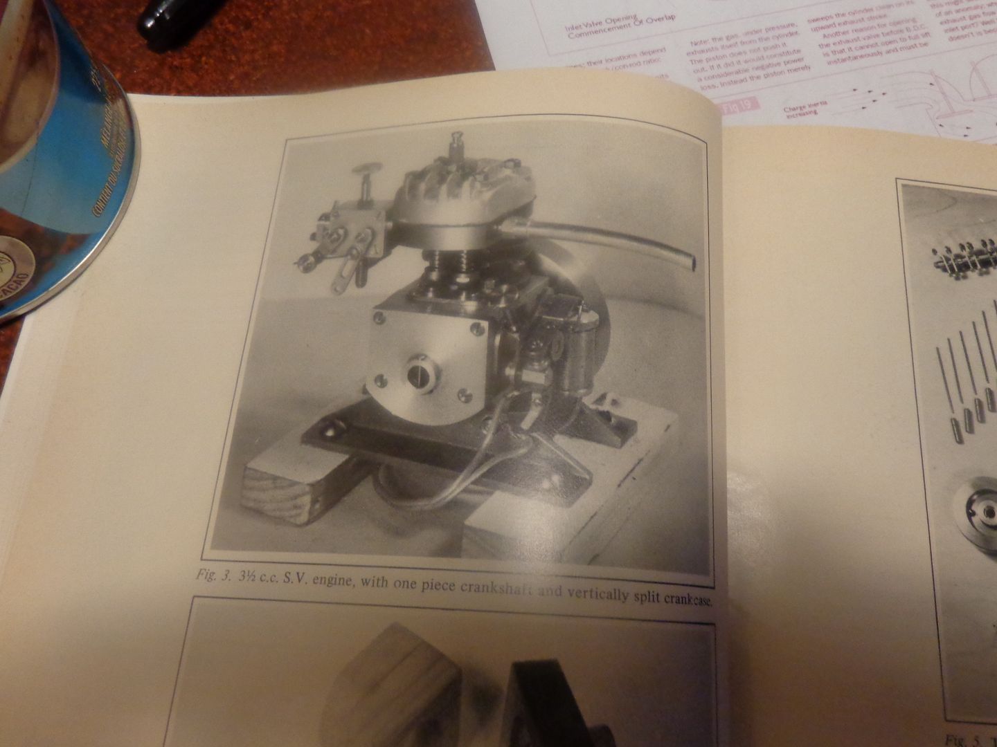
I have a question about side valve engines. I have looked at a number of pictures of side valve engines, and they seem to fall into two categories. One is as per the Philip Duclos Gearless engine, where the cylinder is a plain bore separate part and the combustion chamber is actually in the head, which bolts to the top of the cylinder. The valve cages, seats, and housings bolt onto the outside of the head and are connected to the combustion chamber in the head through passages drilled through the sides of the head. The piston does not travel up into the head, but stops flush with the top of the cylinder.
T he other type, (and I'm really not sure about this) seem to have a plain bore cylinder, then a separate piece with the combustion chamber and valves buried in it bolted to the top of the cylinder, and then a flat, rather featureless (except for sparkplug hole and cooling fins) head bolted to the top of this intermediate piece.
It kind of LOOKS like the piston would have to travel up part way into this intermediate piece, but I just can't imagine a bolted joint that the piston and rings would have to travel over. (see picture) ----Or--is it possible that there is a cast iron liner that fits down through the intermediate piece and the cylinder so the piston can travel all the way without passing over a joint? Who can set me straight on this.----Brian
 
Last edited:
Not really up on this but see herehttp://en.wikipedia.org/wiki/Flathead_engine look for POP UP Piston

Mike.
 
Last edited:
A cross section of the ETW Whippet if this helps. Have to be adapted for air cooling of course.
Gail in NM

Capture.jpg
 
The only major difference I see between the engine in this link that DP posted and the engine I might consider building is that on this engine the round cylinder and the part directly above it which houses the valves is all whittled from one solid chunk. I could do that--but it would be a bit of a pig to cut the cooling fins on.--Wouldn't be able to use the lathe.--At least not on the part above the round cylinder.--Of course the round part of the cylinder is down towards the bottom of the piston skirt, so probably doesn't need fins on it anyways.
https://www.flickr.com/photos/15794235@N06/5245356917/
 
Last edited:
Brian I have mucked about with sidevalve motorcylce engines for many years but not familiar with the model engines you refer to. However, it would seem on basic principals universal to both that you would either have to have a liner going down through the valve holding layer of the sandwich and the cylinder itself so the piston rings had no step to cross.

Or, looking at the photo you posted, it looks and seems quite possible that the piston comes only to the top of the cylinder. The sandwich layers containing the valves and seats off to one side of the cylinder would also have the combustion chamber shaped machined into it, a sort of kidney shaped hole that opened into the bore but machind only halfway through the thickness of the layer in the area around the valve seats and between the seats and the cylinder. The intake and exhuaust gasses would flow in and out the cylinder through this space.
The finned head bolted on the top would be dead flat on its bottom as all gas flow would take place below it in the valve layer of the sandwich.

If you wanted to up the compression a little with this design, you could use a "pop up" piston as Harley Davidson did on their sidevalve KR racers. The top ring comes to the top of the bore at TDC but their is a large land above the top ring so the piston body sticks up into the combustion chamber at TDC. This gives higher compression at TDC without restricting gas flow on the intake stoke, which is what happens if you make the combustion chamber too small on a sidevalve. The "throat" between the valves and bore must have sufficient depth to allow gas flow. So any compression ratio much over 6.5 to 1 on a flathead is usually restricting gas flow and robbing more HP than the increased combustion pressure creates.

If i were making the "sandwich" type arranngement, I would go with the latter option. It seems simpler and more robust than the sleeved option. Purely just my opinion though.

One of these days I will get around to making that working model Harley flathead engine I have been thinking about for , oh about 40 years! Like you, I reckon machining the unsymetrical cylinders with the ports and valve seats incorporated in one lump will be the hardest part, without a mill. Been looking at the principles of ornamental turning to see how they used to do that stuff. One of these days...
 

Latest posts

Back
Top