PatWankel Rotary Engine

Home Model Engine Machinist Forum

Help Support Home Model Engine Machinist Forum:

This site may earn a commission from merchant affiliate links, including eBay, Amazon, and others.

manolis

Well-Known Member
Joined
Jul 18, 2016
Messages
88
Reaction score
38
I just received this email from your forum:

"manolis,

We have been missing you on Home Model Engine Machinist for some time now.

If you get a chance, please log in and let us know what you've been doing lately.

http://www.homemodelenginemachinist.com"


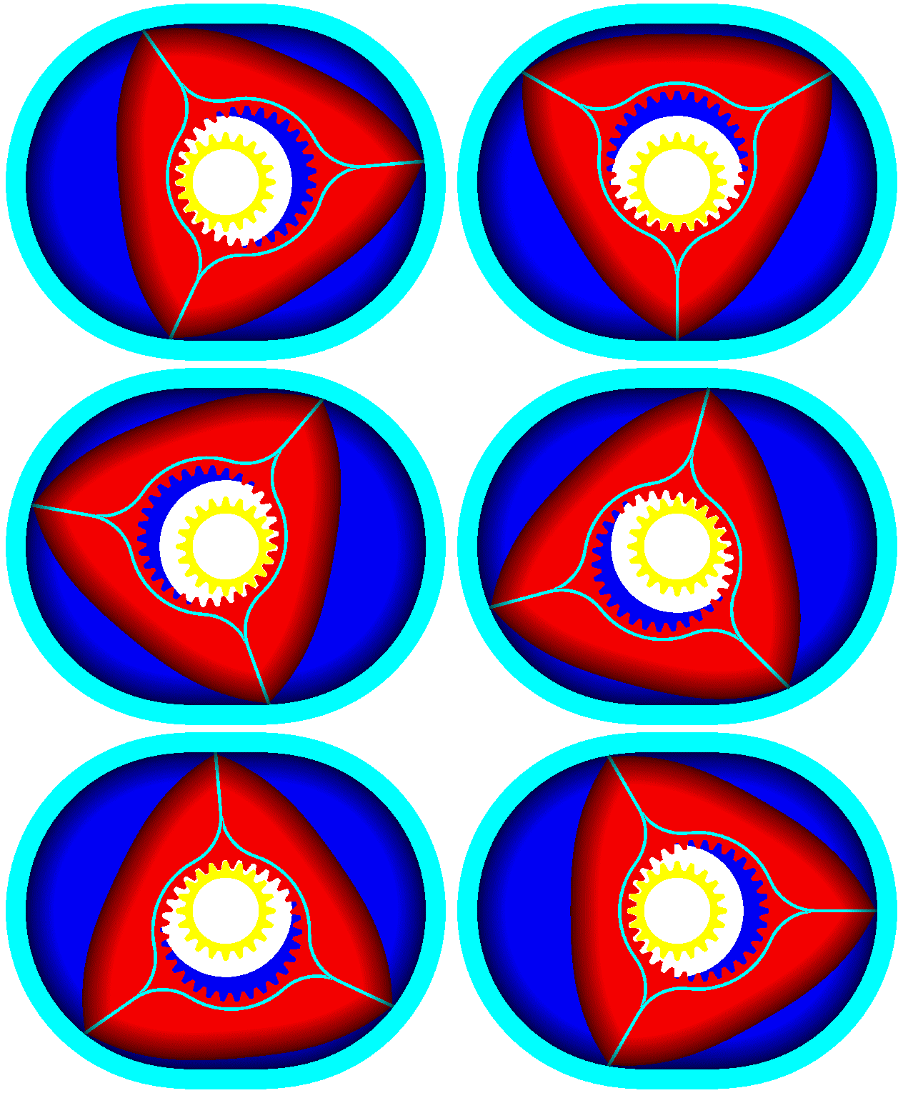
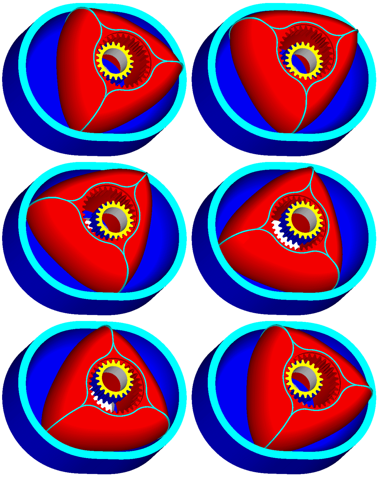
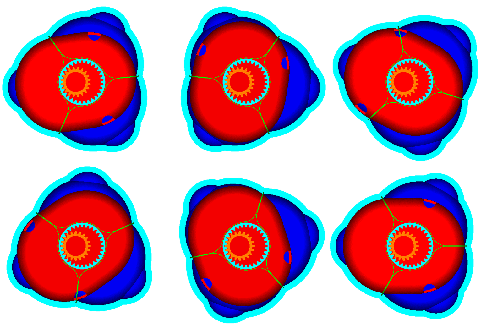
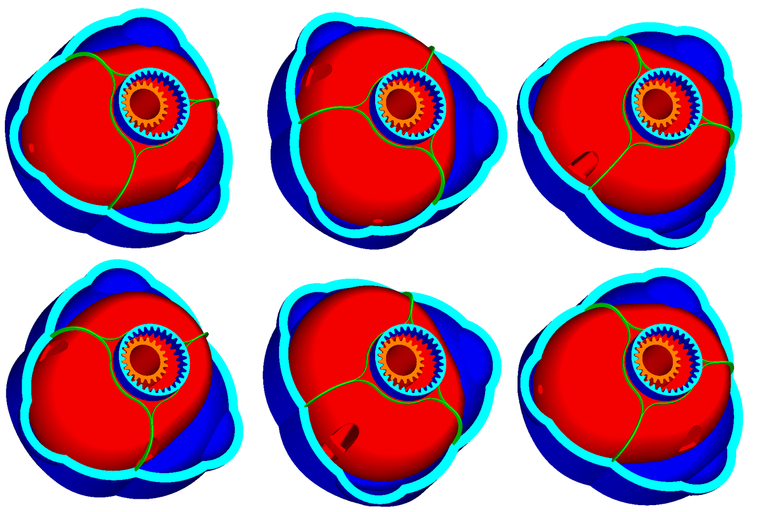
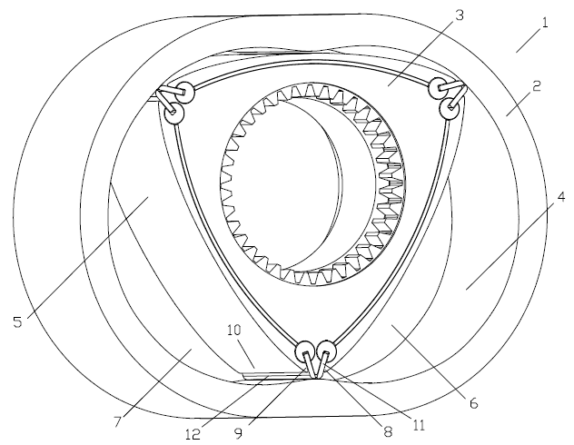
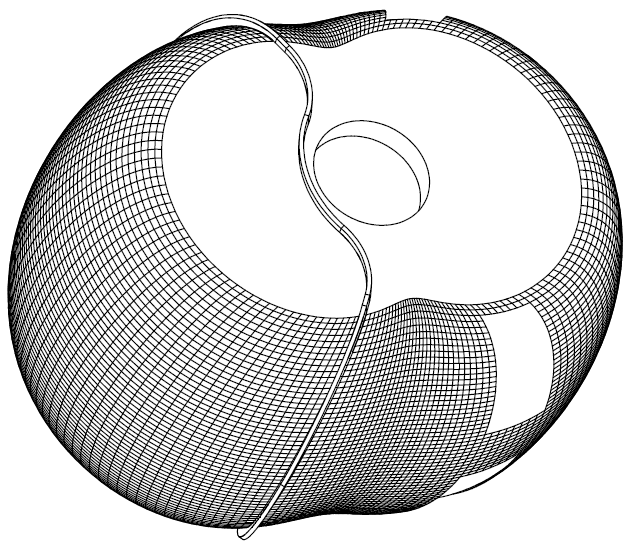
In response, here is the PatWankel Rotary Engine, the most recent project we are dealing with:

PatWankel1.gif


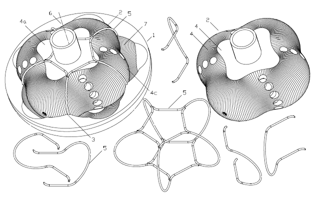
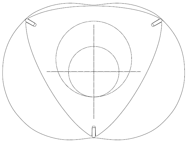
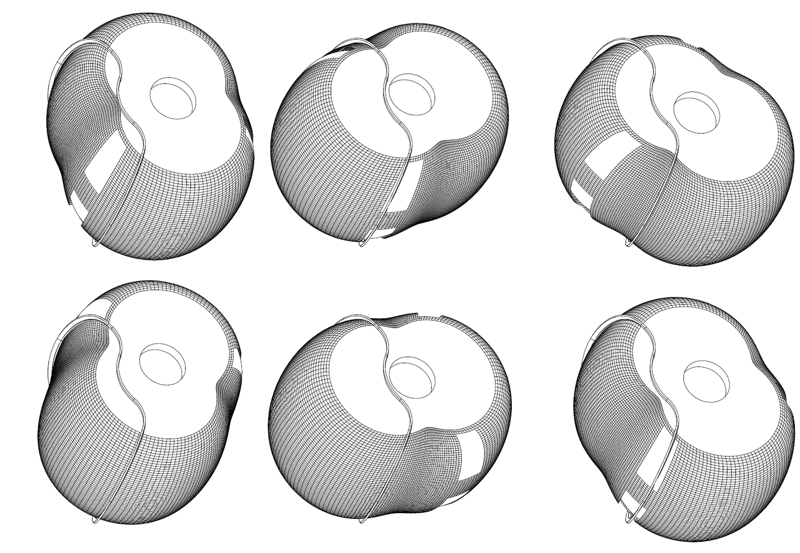
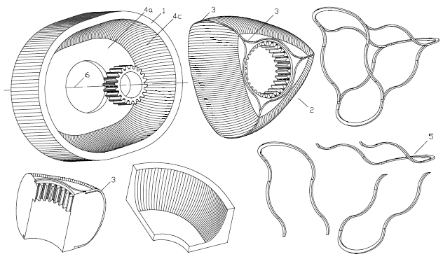
The working surface whereon the seals abut is not a “cylindrical” surface but a 3D curved surface ending smoothly / tangentially on the side flat surfaces of the casing.

PatWankel21.gif


PatWankel2.gif


PatWankel_W_1.gif


PatWankel_W_2.gif


The typical “Wankel sealing grid” (wherein: each combustion chamber is sealed by a set of two side seals, two apex seals and four button (or corner) seals) can be replaced by a single piece seal per combustion chamber.


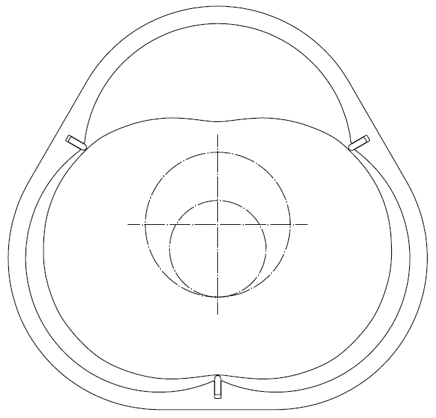
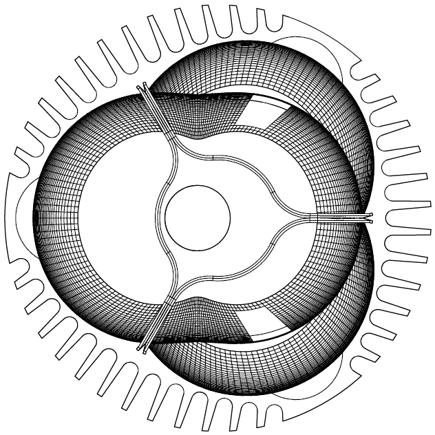
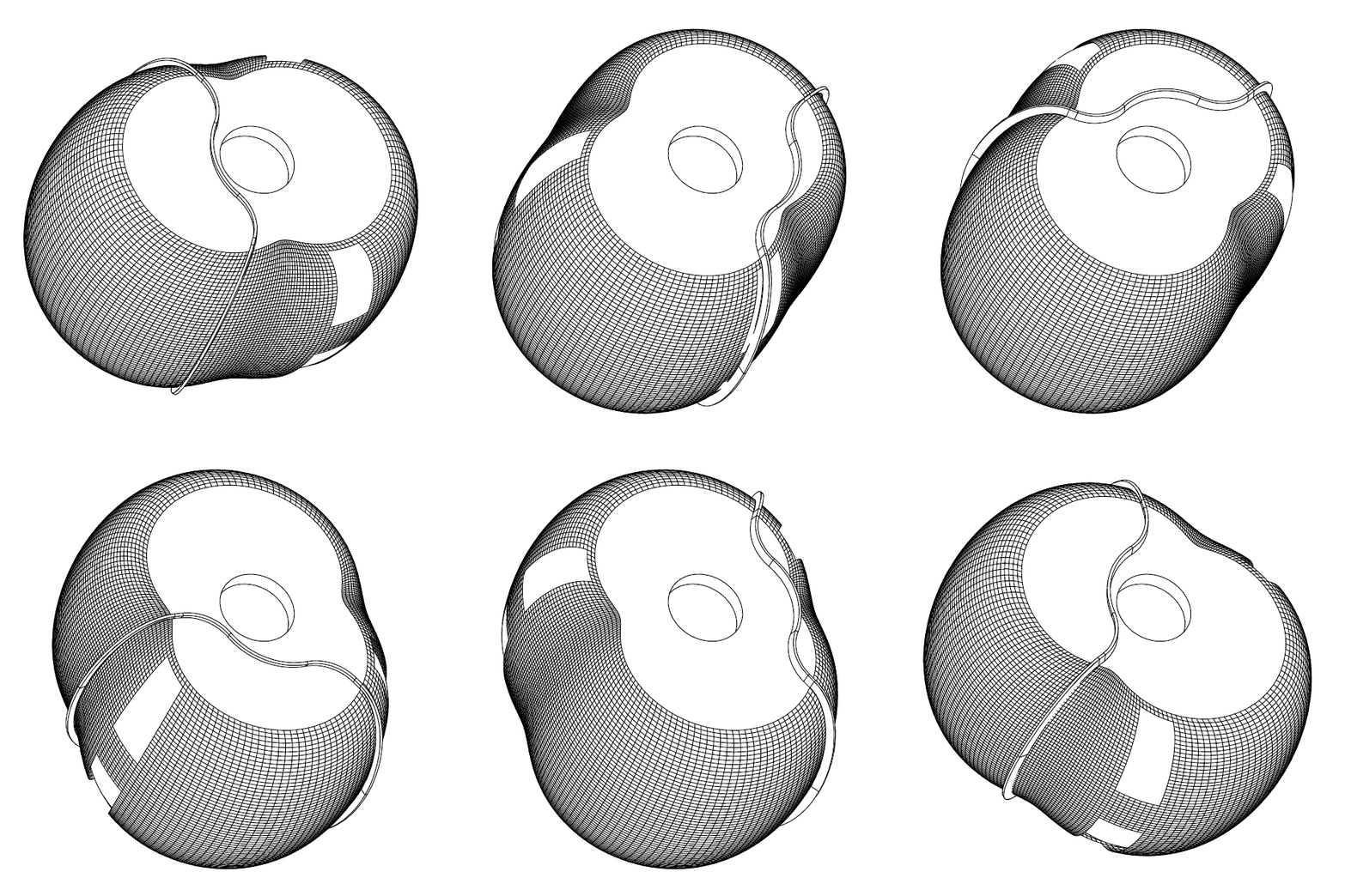
Here is a PatWankel wherein the working surface is on the inner body (say as in the Liquid Piston engine):

PatWankel3.gif


PatWankel4.gif


PatWankel_L_1.gif


PatWankel_L_2.gif


PatWankel17.gif


One seal per combustion chamber, as in the reciprocating piston engines.


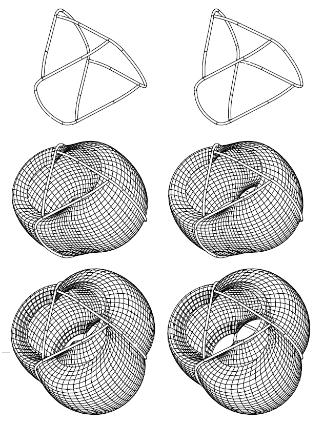
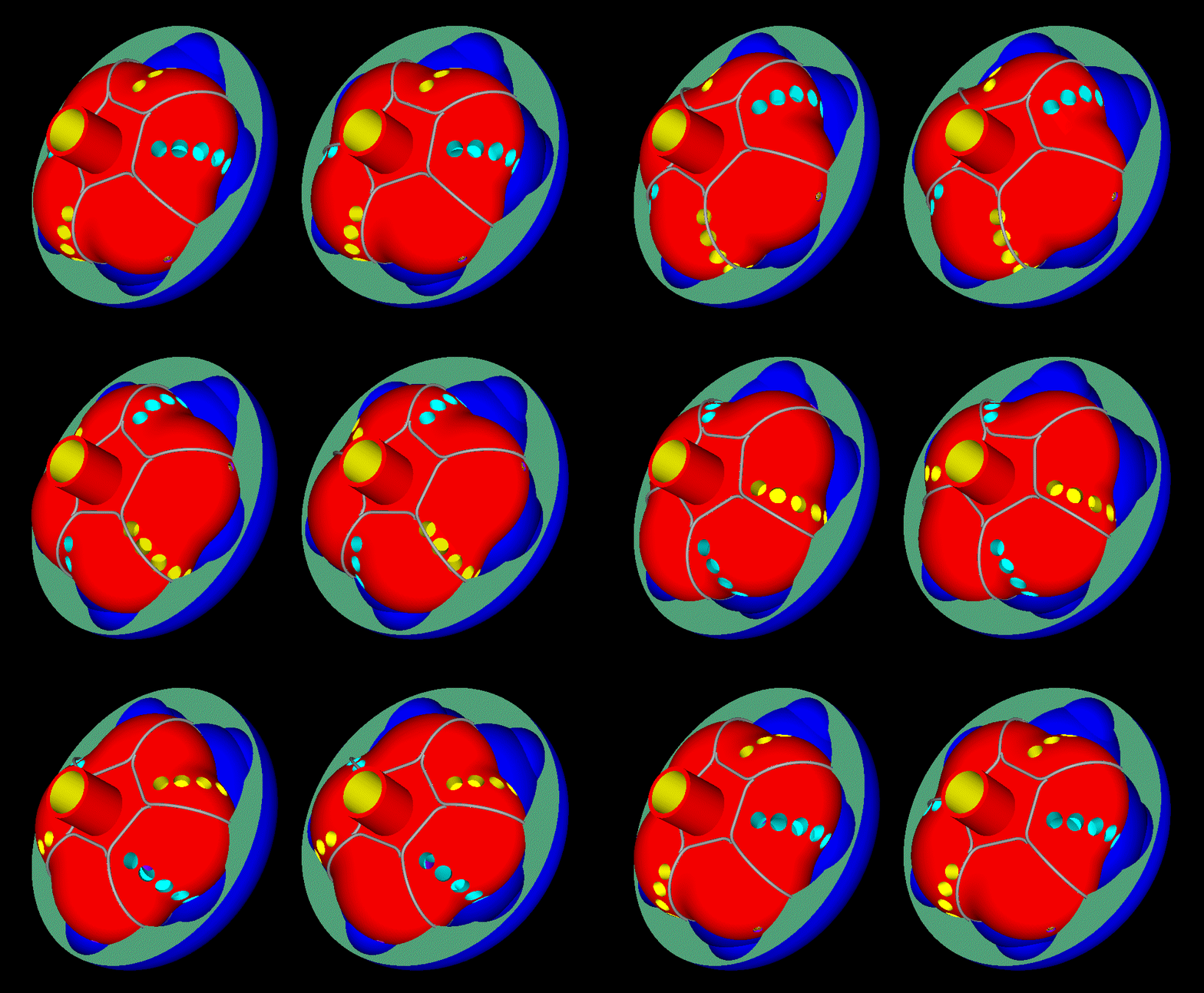
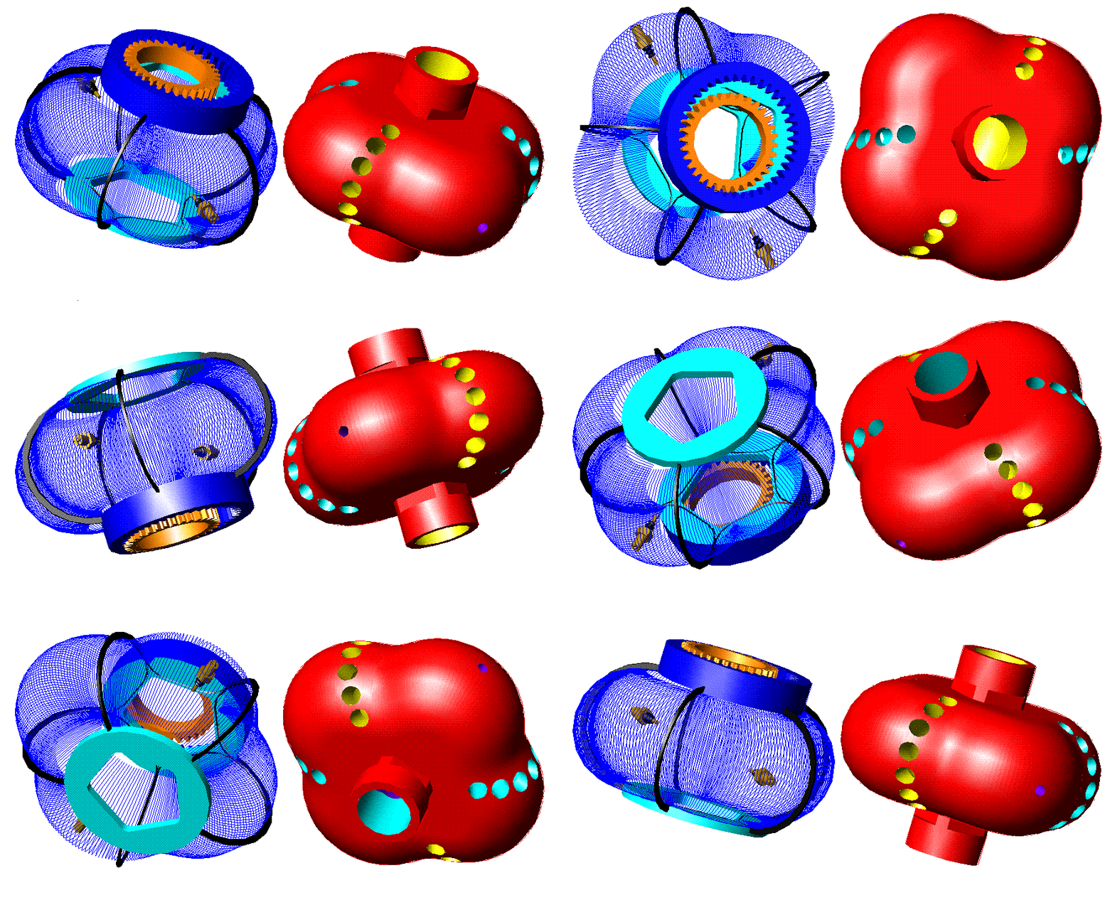
This five “cylinder” PatWankel rotary ( stereoscopic view, as at http://www.pattakon.com/pattakonStereoscopy.htm ) :

PatWankel_Five_STE_1.gif


has two combustions per rotation of the inner body, i.e. as much as a two-rotor Wankel Rotary (say, Mazda RX-8).

PatWankel5.gif


PatWankel10.gif


PatWankel19.gif


Does the oval seal at bottom middle remind the Honda NR750?

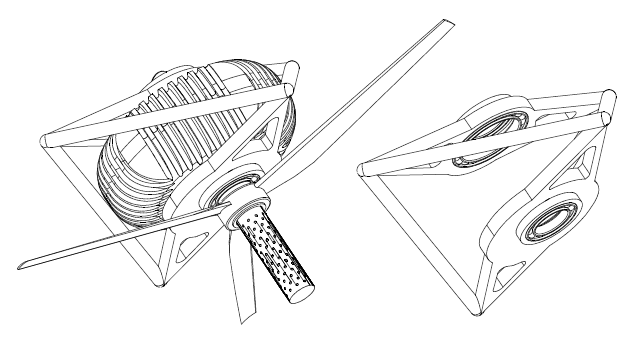
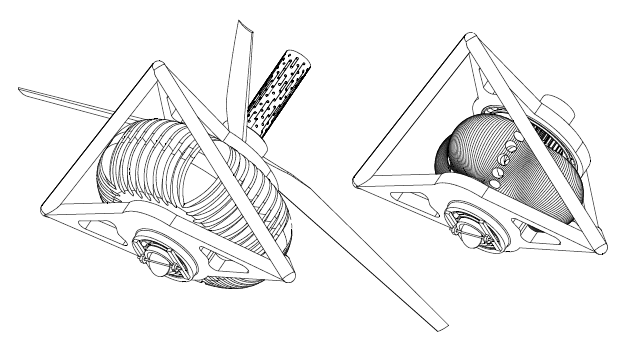
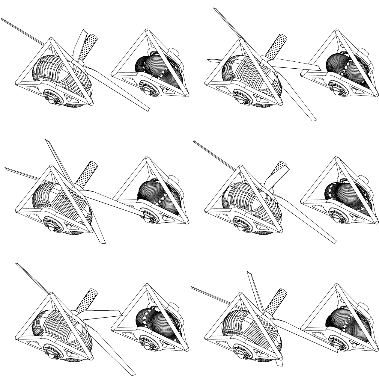
Imagine this PatWankel engine at the back of an airplane pushing forwards:

PatWankel11.gif


PatWankel12.gif


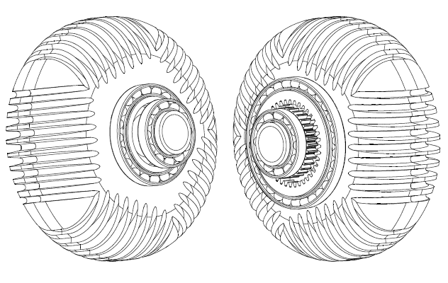
The outer body (that with the cooling fins) spins at 4/5 (80%) of the speed of the inner body:

PatWankel_Pusher.gif


There is no eccentric shaft.
There are no balancing webs.
However it is perfectly balanced.


For more: http://www.pattakon.com/pattakonPatWankel.htm


Thoughts?

Objections?

Thanks
Manolis Pattakos
 
Here we go again,look's like Manolis has invented the Wankel engine this time.
 
The main problem:
1. The tools to create the shape of rotor and rotorhouse.
2. Will it last and how to ovehaul the engine?

Manolis is clever in drawings of wankel engine and lack of tools to create the real wankel engine.
 
Hello all.


I think the following analysis and quotes can make clearer the reasoning behind the PatWankel engine.

In the conventional Wankel Rotary the flame sees way bigger surfaces (and has to travel along way longer distances) than in a conventional engine.

The surface to volume ratio during combustion, only partly explains the increased thermal loss and the emissions of the Wankel.

The high surface to volume ratio is one only of the issues of the conventional Wankel.


According the “Liquid Piston” at www.liquidpiston.com, their non-Wankel engine

giphy1-1.gif


runs closer to a constant volume combustion than the reciprocating piston engines.

Last year DARPA signed a $1M agreement with Liquid Piston.


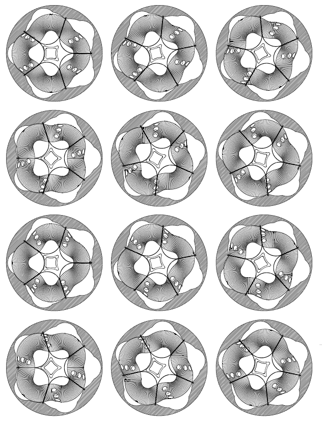
Take the five “cylinder” PatWankel shown in the drawings / animation.
At TDC (i.e. wherein the volume of the working chamber is minimised) almost all the air / mixture entered into the working chamber is concentrated in a compact cavity (spherical or semi-spherical etc).

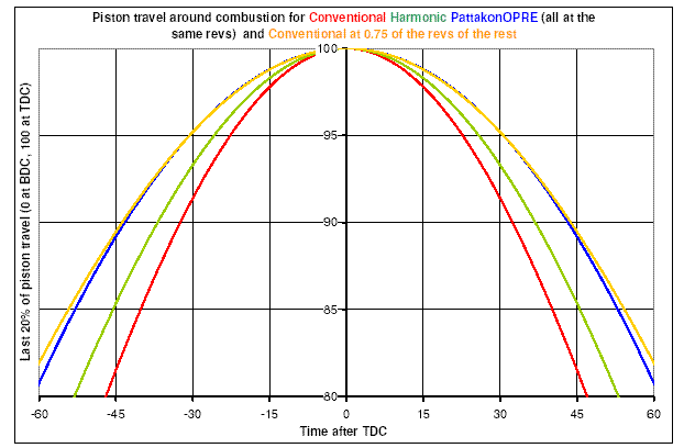
As compared with a Ducati Panigale 1299cc reciprocating piston engine running at the same revs with the revs of the inner body of the PatWankel, the PatWankel provides more than 40% additional time around the TDC (1.15*1.25=1.43)

The 15% longer dwell at the TDC comes from the harmonic (i.e. pure sinusoidal) variation of the combustion chamber volume:

OPREdwell.gif


the 1.25 comes from the 225 degrees required in order the chamber to go from its TDC to its BDC (wherein the volume is maximised):

PatWankel20.gif


There is plenty of time, lots of squeeze and a very short distance for the flame to travel, enabling the combustion to actually complete inside the compact cavity.

Most of the thermal loss happens during the combustion.

The thermal loss continuous during the expansion, however the rate of thermal loss during the combustion is way higher.

Compare it with the thermal loss in a Ducati Panigale 1299 wherein the flame, during the combustion, sweeps the inner surfaces of a wide (116mm diameter) short (about 5mm height) cylinder (like a coin) having abnormal bottom and top (valve pockets etc).
Reasonably, the thermal loss towards the walls during the combustion will be substantially more than in the above PatWankel.


So, there are reasons for lower thermal loss in the PatWankel, despite the bigger (than in a reciprocating piston over-square engine) area of its wall surfaces.


Quote from:
http://gasturbinespower.asmedigitalcollection.asme.org/article.aspx?articleid=2467298

“Abstract
The Wankel rotary engine offers a greater power density than piston engines, but higher fuel consumption and hydrocarbon emissions, in large part due to poor gas sealing. This paper presents a model for the deformable dynamics of the side seal, which completes a set of modeling tools for the comprehensive assessment of the gas leakage mechanisms in the rotary engine. It is shown that the main leakage mechanisms for the side seals are: (1) opening of the inner flank due to the contact with the trailing corner seal, (2) flow through the gap with the leading corner seal, (3) simultaneous opening of both inner and outer flanks due to body force at high speed, and (4) running face leakage due to nonconformability at high speed. The leakage mechanisms are qualitatively validated at low speed with observed oil patterns on the rotor from laser-induced fluorescence (LIF) experiments. Finally, the predicted total leakage area for all the gas seals ranges from 1.5 mm2/chamber at low speeds to 2 mm2/chamber at high speeds, which is in agreement with the previous experimental studies, and the three gas seal types (side seals, apex seals, and corner seals) each accounts for about 1/3 of the total leakage, with minor variation as a function of speed.”
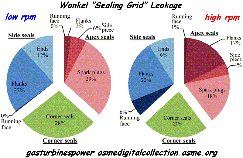
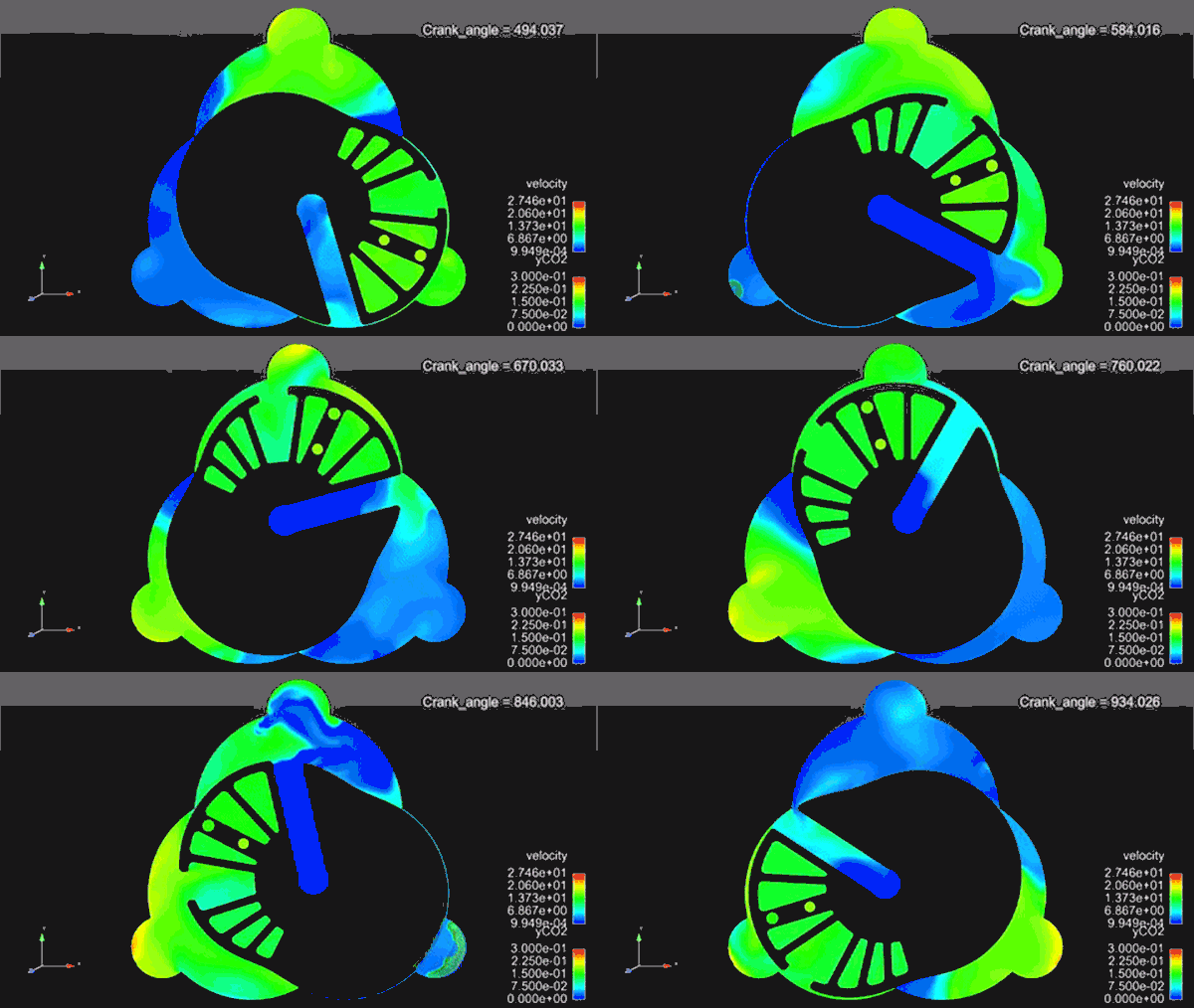
Wankel_leakage.gif


End of Quote


According the above abstract / plot, the leakage is a major problem / issue of the Wankel rotary engines.

Each cylinder of the Panigale 1299 has a capacity of 650cc, i.e. as much as each chamber of the Wankel RX-8.
Take a drill and make one hole of 1.5mm diameter (1.77mm2 area) on each piston crown of the Ducati Panigale, to allow each combustion chamber to communicate, through the hole, with the crankcase.
No doubt, the Panigale can still work, however a significant amount of high pressure gas will escape reducing the efficiency (a lot of energy is consumed to compress the gas that leaks without giving back any energy) and worsening the emissions.

This is the way the conventional Wankel works till now.
The gaps around each combustion chamber have an equivalent total leakage area of 1.5mm2 at low revs, to 2mm2 at high revs.

Compare the leakage from the “running surfaces” with the rest leakage.


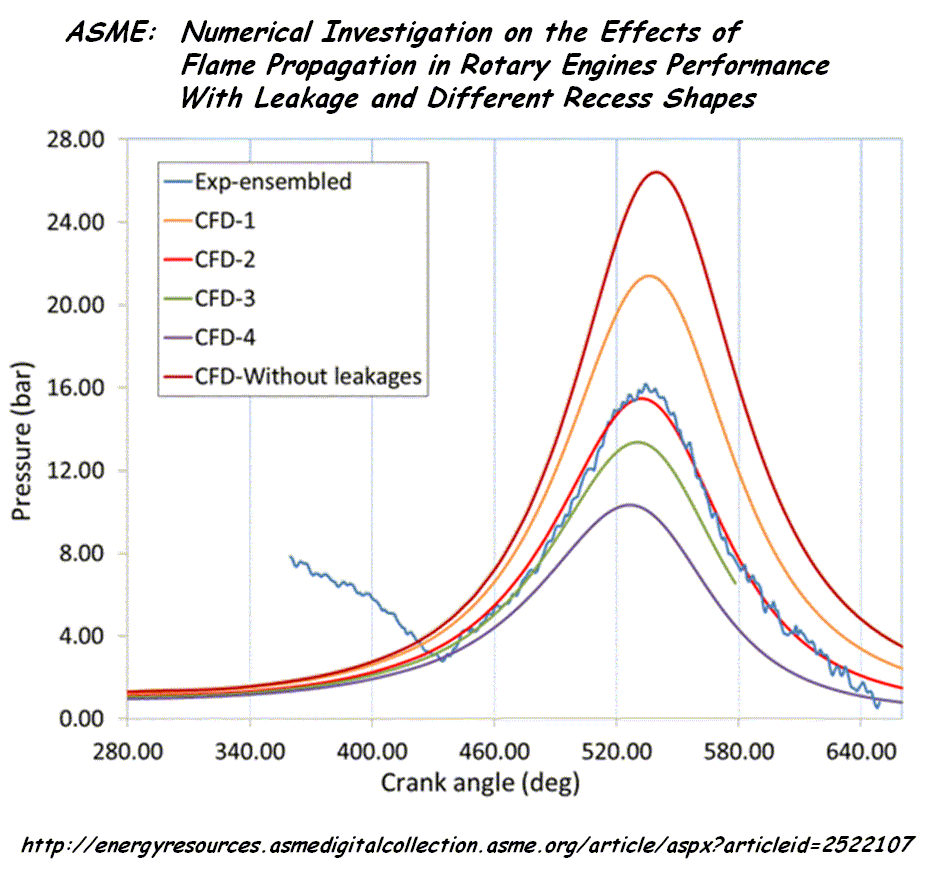
Quote from http://energyresources.asmedigitalcollection.asme.org/article.aspx?articleid=2522107

“Numerical Investigation on the Effects of Flame Propagation in Rotary Engine Performance With Leakage and Different Recess Shapes Using Three-Dimensional Computational Fluid Dynamics”

ABSTRACT

This study was carried out with an objective to develop a 3D simulation methodology for rotary engine combustion study and to investigate the effect of recess shapes on flame travel within the rotating combustion chamber and its effects on engine performance. The relative location of spark plugs with respect to the combustion chamber has significant effect on flame travel, affecting the overall engine performance. The computations were carried out with three different recess shapes using iso-octane (C8H18) fuel, and flame front propagation was studied at different widths from spark location.
Initially, a detailed leakage study was carried out and the flow fields were compared with available experimental results. The results for first recess with compression ratio 9.1 showed that the flow and vortex formations were similar to that of actual model. The capability of the 3D model to predict the combustion reaction rate precisely as that of practical engine is presented with comparison to experimental results. This study showed that the flame propagation is dominant toward the leading apex of the rotor chamber, and the air/fuel mixture region in the engine midplane, between the
two spark plugs, has very low flame propagation compared to the region in the vicinity of spark. The air/fuel mixture in midplane toward the leading apex burns partially and most of the mixture toward the trailing apex is left unburnt. Recommendations have been made for optimal positioning of the spark plugs along the lateral axis of the engine. In the comparison study with different recess shapes, lesser cavity length corresponding to a higher compression ratio (CR) of 9.6 showed faster flame propagation toward leading side. Also, mass trapped in working chamber reduced and developed higher burn rate and peak pressure resulting in better fuel conversion efficiency.
Third recess with lesser CR showed reduced burn rates and lower peak pressure.

Wankel_Flame_Prop.gif


End of Quote.


It is more complicated than “surface to volume” ratio.

According the last plot, if the leakage is avoided, the same Wankel increases its power, reducing at the same time its brake specific fuel consumption (g/kWh).

The surface to volume area remains as high as before.

So, if we could reduce substantially the leakage in the conventional Wankel, an significant increase of the power output and a significant decrease of the BSFC are expected.

This is what the following PatWankel:

PatWankel_W_2.gif


does: it reduces the gas leakage to levels met in the reciprocating piston engines.

If the plot of ASME is not wrong, the improvement (on the power output and on the mileage) on a Mazda RX-8 when modified to PatWankel would be significant.


But there is more.


The other version of the PatWankel (the PatWankel wherein the seals slide onto the surface of the inner body) besides reducing the leakage it performs another significant “task”: it enables a compact combustion chamber to be formed, wherein almost all the mixture is concentrated and is burnt before the expansion.

This improvement may prove in practice more important than the significant reduction of the gas leakage.


The mechanical friction in a rotary engine like the PatWankel 5-cylinder is substantially lower than in an “equivalent” reciprocating piston engine.
There is no valve train.
There are no piston skirts to thrust on cylinder walls.
The four roller bearings on the frame and the sliding of the seals on the working surface are the only cause of mechanical friction.
All the energy / torque passes directly through the shaft of the inner body to the load.
The outer body receives no torque, at all.


[FONT=&quot]If you count all these together (improved sealing, fast combustion into a compact cavity, reduced mechanical friction, simplicity etc) things get more than interesting.
[/FONT]


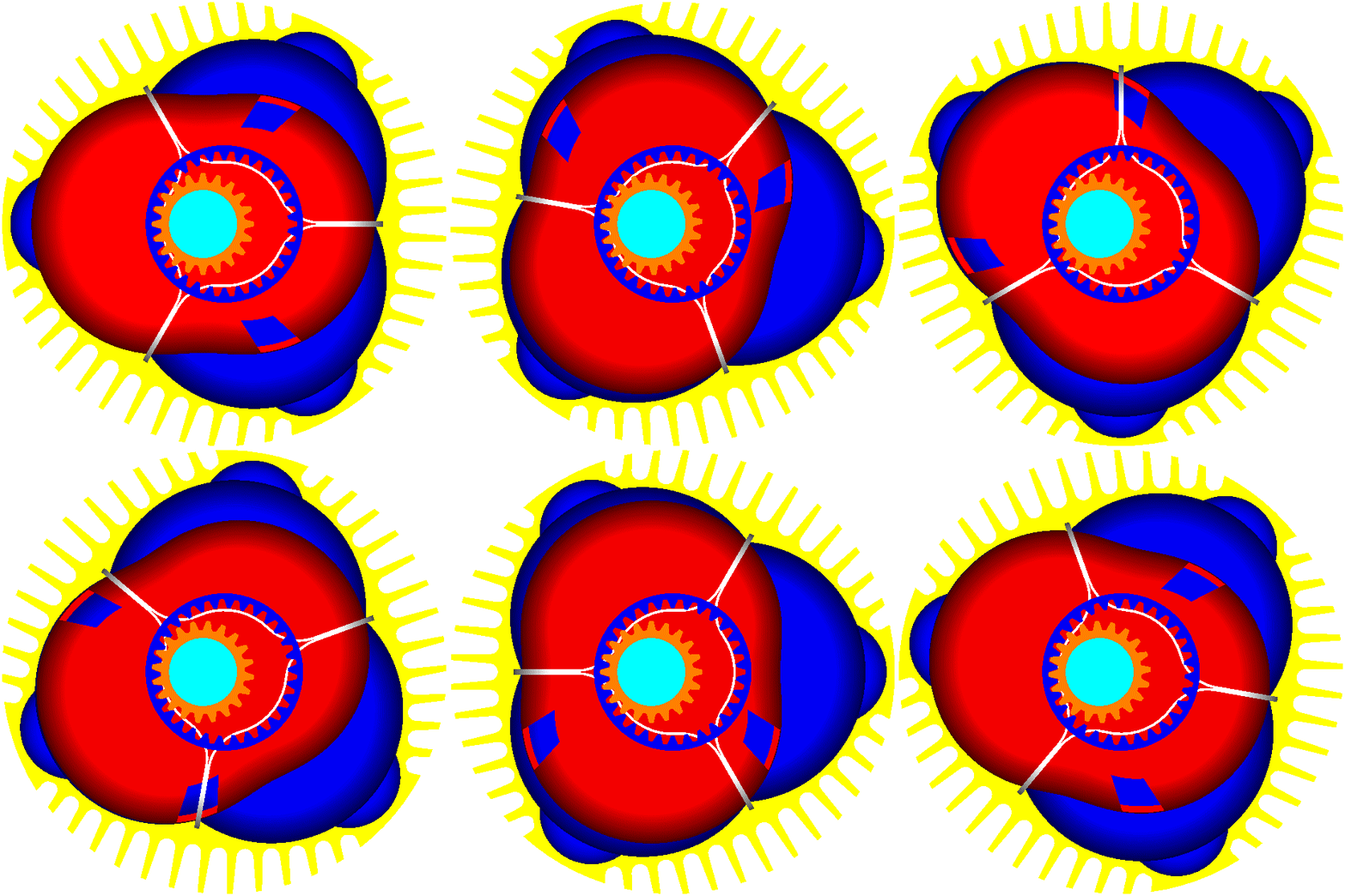
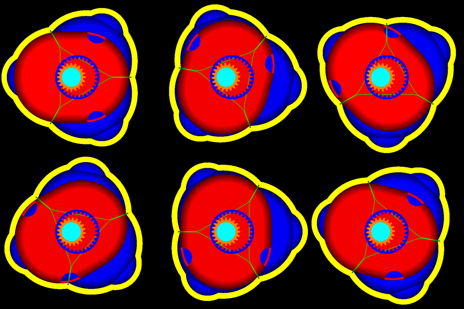
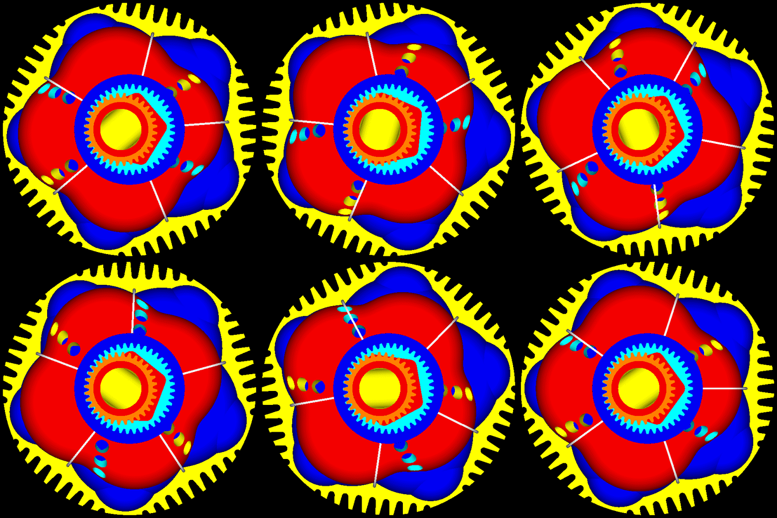
The following animation may-be useful for timing-check reasons:

PatWankel_Triple_Timing.gif


The angle step is 10 degrees (as in the conventional engine, 180 degrees separate the TDC (wherein the volume of a working chamber is minimized) to BDC (wherein the volume of the same working chamber is maximized).

Start counting “frames” (and degrees) the moment the inner body is “horizontal” with the ports at right.

The timing shown is conservative.

The “overlap” may seem big, but it is quite small. This is so because during the “overlap” either the intake ports, or the exhaust ports, or both, are almost closed by the inner surface of the outer body.
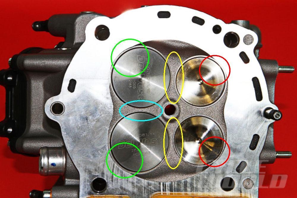
The overlap in this engine is way different than in a, say, Ducati Panigale:

Ducati_Panigale_flow_restrictions.jpg


wherein overlap means, more or less, the “short circuit” between the intake and the exhaust (the area marked by the yellow ellipses) and inevitable loss of unburned mixture,
while in the above PatWankel overlap means a through or uniflow “scavenging” of the chamber by the fresh charge (more or less as in the opposed piston engines) that sweeps / pushes out the burned gas and reducing this way the residual gas.


By the way:


Last month LiquiddPiston received another $2.5 million from DARPA for their rotary engine.
More important: LiquidPiston also received a $25,000 cash prize from Shikorsky along with the opportunity to explore opportunities for LiquidPiston's technology with the Shikorsky product line


Thanks
Manolis Pattakos
 
Fascinating. The problem with the Wankel, Liquid Piston, and similar concepts has always been sealing. Their designs were 2D concepts that could be made accurately with 20th century methods. However, a piston and cylinder was the only way to get a reasonable seal with these methods. Now we can produce complex 3D shapes with high accuracy thanks to digital technology. Maybe for the first time we can seal an engine like this. I am very interested in how you propose to make this engine.

Lohring Miller
 
Hello Lohring

You write:
“Fascinating. The problem with the Wankel, Liquid Piston, and similar concepts has always been sealing. Their designs were 2D concepts that could be made accurately with 20th century methods. However, a piston and cylinder was the only way to get a reasonable seal with these methods. Now we can produce complex 3D shapes with high accuracy thanks to digital technology. Maybe for the first time we can seal an engine like this. I am very interested in how you propose to make this engine.”


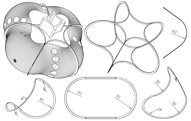
Having the two radiuses (the “crank arm” R1 and the “rotor” radius R2) and the shape of the selected seal (semicircle? oval? Etc), the geometry of the working surface S is fully defined.

PatWankel_Triple_Timing_Sport.gif


A spherical cutting tool is the best for the machining.

Having the radius r of the spherical cutting tool, what is required is a “3-D Offset” by r of the working surface S to a surface S1 whereon the center of the cutting tool will “move” in order to create the S surface. Easier than what it seems initially.

The CNC milling machine is programmed to move the center of the cutting tool on the S1 surface. This will create the S surface on the metal.

If the CNC milling machine has, besides the typical three axes, a fourth axis (rotation about an axis) things get easier. The complete working surface can be made without removing the part.

Otherwise (case without a fourth axis) the working surface will be machined in two (or more) steps.

With the working surface being the external surface of the inner body, the machining is easy. The hollow shaft is ideal for holding the part during the cutting.

The passageways inside the inner body need not accuracy, so the inner body can be mold made of, say, spheroidal graphite iron. Then its external surface is machined as above.


The outer body is to be made of two halves secured to each other. It needs not special accuracy except from the grooves for the seals.


The gearwheels are conventional and easy to be made.


The seals can be cut accurately with a wire EDM machine. After their bending (to fit in the grooves) they need hardening.


If the above are confusing, please let me know to further explanation.


Thanks for asking
Manolis Pattakos
 
I will have to try this new method of bending seals in my next engine, it sounds so easy to make flat strips and then just bend them. No more turning rings, then cutting them, then the heat treatment, this must be a winner.
 
I doubt that milling will leave an accurate and smooth enough surface on the outer case to get good sealing. However, a CNC grinding machine should be able to produce an accurate surface in the same way. An even better surface finish will still be required from some kind of honing or superfinishing method. The inner element can probably be made accurately enough with milling or even advanced 3D printing. Accurate bending of the rings is also tough. NC wire benders might do the job, but I'm not familiar with their accuracy. The first working model will answer a lot of questions and expose the weaknesses of the design. My experience in product development a long time ago found that you never foresaw most of the problems until you actually had them.

Lohring Miller
 
Hello Lohring.

You write:
“I doubt that milling will leave an accurate and smooth enough surface on the outer case to get good sealing. However, a CNC grinding machine should be able to produce an accurate surface in the same way. An even better surface finish will still be required from some kind of honing or superfinishing method.”

You are right about the finishing.

However, when you built one prototype and the budget is limited, after the milling there are simpler/cheaper ways to finish / to polish the working surface.


You are wrong in that the accurate and smooth enough surface (the working surface whereon the seals abut and slide) is on the outer body / case. It is on the inner (the red) body:

PatWankel_Triple_Timing.gif


On the external surface of the inner body (red) is whereon the seals abut and slide.

Only the grooves, made on the outer body / case, need high accuracy. The rest inner surface of the outer body (blue) is not a working surface: nothing slides on it; it gets in contact only with the gas.


You also write:
“Accurate bending of the rings is also tough. NC wire benders might do the job, but I'm not familiar with their accuracy.”

It seems what I wrote for the seals was confusing (Hello Buchanan).

Let me explain what I meant:

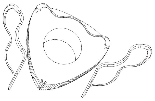
From a steel sheet (say 1.5mm width) with a wire EDM machine the seal is cut accurately, say, as it appears at bottom – middle in this drawing:

PatWankel19.gif


Then the seal is slightly bend to fit in its groove on the external body (as shown at bottom left and bottom right, radius R2). The radius R1 remains unaffected by this smooth bending.

With a nitride surface hardening the dimensions remain unchanged and the seal is ready to be used.

The seal needs a cut somewhere, say as shown here (bottom middle):

PatWankel3.gif
.


Worth to be noted: we talk for the manufacturing of one prototype PatWankel engine at low cost. Not for production.

So, the R1 surface does not result from the bending of a metal strip. It comes from the accurate cutting, with a wire EDM machine, of a steel sheet.

I hope it is more clear now.

Thanks
[FONT=&quot]Manolis Pattakos[/FONT]
 
Thanks. For some reason I didn't realize that the seals were in the outer case. However, everything I said about an accurate and smooth surface is still true. It just needs to be on the inner element. It may be easier to get this finish and the seals may wear in well enough against say a cast iron inner element for a demonstration prototype. Production engines would need a better solution for long life. I'm looking forward to seeing your prototype. This could be a very promising design.

Lohring Miller
 
EDM cutting leaves a porous hardened surface, if you propose to use an alloy steel this hardened surface will crack when bent. Do you have a miraculous post bend finishing process that will remove the cracks and produce the smooth non abrasive surface required for a long lasting oil and pressure seal?
 
Hello Buchanan

You write:
“EDM cutting leaves a porous hardened surface, if you propose to use an alloy steel this hardened surface will crack when bent. Do you have a miraculous post bend finishing process that will remove the cracks and produce the smooth non abrasive surface required for a long lasting oil and pressure seal?”


The porous hardened surface is a good characteristic (it keeps lubricant etc).

There are some “miraculous” multi-axis wire EDM machines by which you can cut accurately an already bent sheet of metal, and so you bypass the problem mentioned.

Such EDM machines cut accurately bevel gears etc.

Thanks
Manolis Pattakos
 
Hello Lohring

Talking for the seals of the Wankel, LiquidPiston and PatWankel, here are some interesting, I hope, details:

With their different arrangement of the seals, LiquidPiston creates new “sealing” problems (not existing in the Wankel engine).

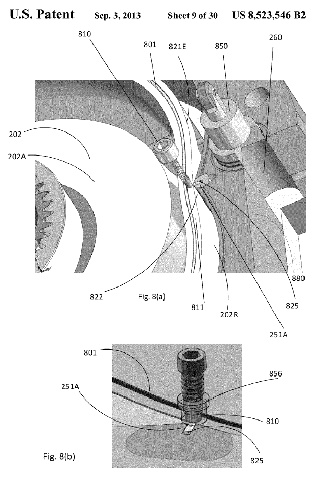
According the following drawing (from the patent of LiquidPiston):

LiquidPiston_US.gif


there is an immovable “peak” seal, 825, which abuts on the cylindrical working surface 202R of the inner body,

there is also a side seal, 801, in a groove of the inner body, which follows the motion of the inner body.


A LiquidPiston side seal, as the seals of the conventional Wankel, undergoes a substantially variable (in direction and in amplitude) acceleration around the seal and around the cycle.

Here is the inertia force an apex seal of a conventional Wankel applies to the epitrochoidal casing :

Wankel_Apex_Seal_Acceleration.gif


(at some angles the inertia vectors outwards, at some other angles it vectors inwards),


and here is the acceleration required in order a point at the top edge (the outmost edge) of the side seal of a LiquidPiston engine to follow the motion imposed by the spinning / orbiting rotor:

LiquidPiston_Side_Seal_Top_Acc.gif


and here it is shown, for comparison, the acceleration required in order a point at the innermost edge of the side seal of a LiquidPiston engine to follow the motion imposed by the spinning / orbiting rotor:

LiquidPiston_Side_Seal_Middle_Acc.gif


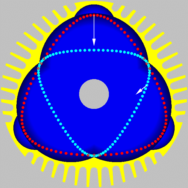
The following drawing helps in understanding the previous plots (the red circles show the path the outmost edge of the side seal follows, the cyan circles show the path the innermost edge of the side seal follows) :

LiquidPiston_SideSeal_Acc.gif


R1 is the "crank-arm" of the eccentric shaft, R2 is the distance of the specific point of the seal from the center of the rotor.


The gaps between the apex-seals /corner-seals / side-seals of the Wankel engine are gaps between bodies moving together (they are all inside grooves / holes of the rotor).


In the LiquidPiston, the side seal moves together with the inner body (the rotor), while the rest seals are stationary.
Any clearance of the synchronizing gear-wheels,
and any clearance in the bearings supporting the rotor (the bearing by which the rotor is rotatably mounted on the eccentric shaft and the bearings by which the eccentric shaft is rotatably mounted on the immovable casing),
and any “play” of the side seal inside its groove,
and any flexing of the eccentric shaft (or power shaft) due to inertia and/or combustion loads,
all are added to the required gap between the side seal and the “button seal”.
Note: around each chamber there are four such gaps.

The result is even more gas leakage than in the conventional Wankel.


Now think how the seals are arranged and are working in the PatWankel.

In the PatWankel with the working surface on the inner body, all the seals are inside grooves made on the outer body and perform a pure rotation (during a cycle, the inertia force remains constant in direction and constant in amplitude). Etc.


By the way, without an eccentric shaft, there is no flexing of the eccentric shaft.
Without inertia loads on the bearings, the clearance between the inner and the outer bodies is smaller.
Without eccentric shaft, no balance webs are required.

Thanks
Manolis Pattakos
 
Hello all.

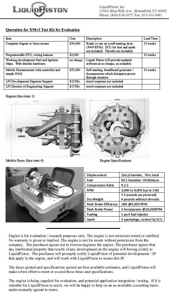
Here are the specifications of the XMv3 of LiquidPiston:

LiquidPistonXMv3Kit.gif


According the famous MIT university, the DARPA and the more than famous Shikorsky company, it is a promising engine design.


Here are a few calculations based on the above specifications and on the way the XMv3 operates.

They are required two only rotations of the eccentric shaft in order a combustion to take place in each working chamber (of the three existing). This means 1.5 combustion per eccentric shaft rotation.

In comparison, in a Wankel they are required three eccentric shaft rotations in order a combustion to take place in each working chamber (of the three existing). This means one only combustion per eccentric shaft rotation.

More combustions per shaft rotation sounds great.

However there is a significant side effect:
In the Liquid Piston the synchronizing gearing is heavily loaded by the combustion pressure.
Depending on the angle of the eccentric shaft, the teeth of the two gearwheels take a good percentage of the force acting on the “rotor” due to the high pressure gas.

In comparison the synchronizing gearing of a Wankel runs unloaded for as long as the engine runs at constant rpm.


At 10,000rpm the power output of the XMv3 is 3PS.

According the previous, 10,000rpm means 5,000combustions per working chamber of the XMv3.

Unless I am wrong, this is equivalent to a 70cc 4-stroke reciprocating piston engine operating at 10,000rpm (because it also burns 5,000 times per minute the mixture contained in a chamber of 70cc).

A good 4-stroke makes more than 100mN of torque per lit (1,000cc) of displacement (even at the peak power revs).
This way, a torque of 7mN from a 4-stroke 70cc reciprocating piston engine is reasonable.

7mN at 10,000rpm means a power output of 14*7mN*10= 10PS.

This is more than 300% of what the XMv3 makes.

Do I miss something?

Thanks
Manolis Pattakos
 
Hello all.

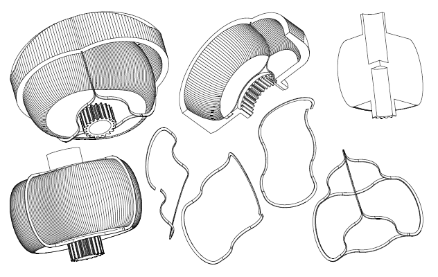
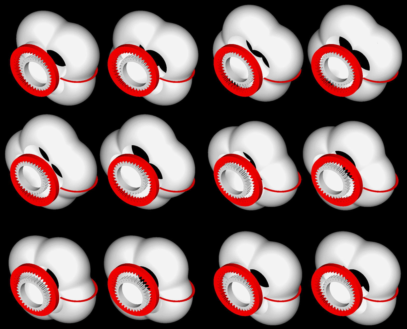
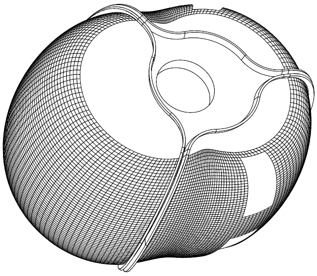
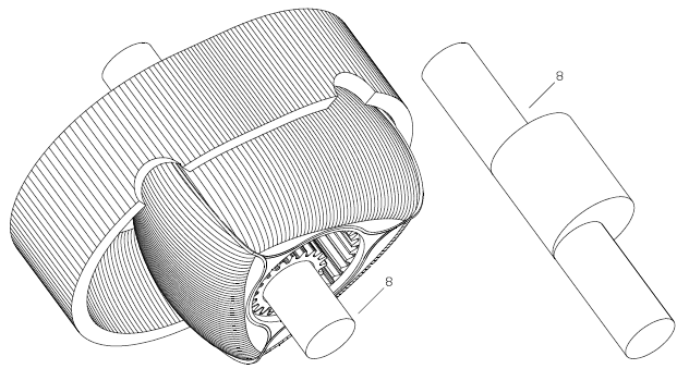
Here is the inner body of an unconventional rotary engine and the way to cut it in a lathe:

PatWankel_Five_Cut.gif


(instructions in how to see it stereoscopically at http://www.pattakon.com/pattakonStereoscopy.htm )


At operation it would be like:

PatWankel_Five_front.gif


It comprises two only parts, each spinning at constant speed about its own fixed axis (which means perfect balancing without any balance webs).
The eccentric shaft of the Wankel RX8 and of the LiquidPiston rotary engines is eliminated.
The power / torque is delivered by a shaft / extension of the inner body:

PatWankel_Five_lines.gif


There are two combustions per shaft rotation (i.e. as much as in a Wankel with two rotors).

The big difference is in the sealing.

More about how this engine (PatWankel) operates are at http://www.pattakon.com/pattakonPatWankel.htm


Regarding the machining of the working surface shown in the first animation:

On the chock of a lathe it is secured eccentrically a shaft.
The red gearwheel is secured immovable on the lath bed.
The body with its gearwheel (white) is rotatably mounted on the shaft.
As the chock rotates, the body to be machined performs a combined motion (it spins about the shaft and it orbits together with the shaft).
Given the shape of the seals to be used (the simplest form? the circular), the cutting tool has to follow a specific “path” (like half circle, for instance) in order to create / form the working surface on the part (the working surface is whereon the seals will abut and slide during operation; the seals are mounted in grooves made on the outer body).

In case of seals having simple form, even a conventional (not CNC) lathe can be used.

Similarly for the honing / polishing.


Thoughts?

Objections?

Thanks
Manolis Pattakos
 
That will work with both cutting tools and a grinder mounted like common ball cutters. The next problem is machining the seal slots in the outer body. To follow the inner body their location and contour needs to be fairly accurate, but the width needs to be very accurate. I can envision an end mill on a cnc mill cutting the groove in each half. I don't believe you can depend on springs to make up any inaccuracies. Also, the seal seems to transition from riding on the spherical surface to the flat surface on the ends of the inner element. That will be tough to seal with a one piece ring. Perhaps you would do better with a multi piece seal. I can envision a 1/2 circle segment for the outer section combined with circular arc face seal segments near the hub. They could be connected by a cylindrical piece like the Wankel apex seals.

Lohring Miller
 
Hello Lohring

You write:
“That will work with both cutting tools and a grinder mounted like common ball cutters. The next problem is machining the seal slots in the outer body. To follow the inner body their location and contour needs to be fairly accurate, but the width needs to be very accurate. I can envision an end mill on a cnc mill cutting the groove in each half. I don't believe you can depend on springs to make up any inaccuracies.”

I was thinking of the manufacturing of the grooves exactly as you write it.


You also write:
“Also, the seal seems to transition from riding on the spherical surface to the flat surface on the ends of the inner element. That will be tough to seal with a one piece ring. Perhaps you would do better with a multi piece seal. I can envision a 1/2 circle segment for the outer section combined with circular arc face seal segments near the hub. They could be connected by a cylindrical piece like the Wankel apex seals.”

As shown in the ASME papers (previous posts), one of the big problems of the Wankel rotary is the excessive gas leakage through the gaps between the several parts comprising the Sealing Grid.

This is what the PatWankel tries to do. To apply the efficient sealing of the reciprocating piston engines to the rotary engines.


At http://www.pattakon.com/pattakonPatWankel.htm web page it has been added another version of sealing for “gerotor” rotary engines (Wankel, Colley, LiquidPiston etc), as follows:

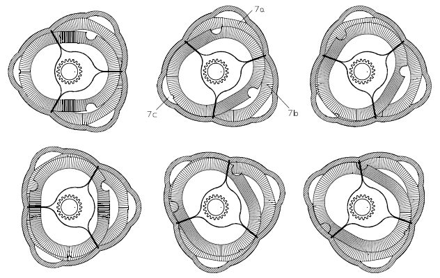
A common characteristic of the prior art rotary engines is that some of the seals, and some of the seal grooves, are shared between neighbour working chambers.

In comparison to a reciprocating piston engine, a Wankel rotary engine uses two apex seals per working chamber, with the one apex seal (and its groove) shared with the leading working chamber, and with the other apex seal (and its groove) shared with the trailing working chamber. In this version, each combustion chamber utilizes not only its own seals, but also its own grooves for seals.

PatWankel_iGR_10.gif


The apex seal "plays" inside its groove on the rotor, bouncing between the two flanks of its groove.
For instance, the "leading" apex seal of a chamber, when the exhaust starts in the leading chamber, leaves the "trailing flank" and moves towards the leading flank of its groove, allowing a significant leakage towards the exhaust. At the end of its "stroke" it slaps the "leading flank" of its groove.


There are similar problems in the Reverse_Wankel / LiquidPiston rotary engine: each "peak seal" with its groove is shared between two neighbouring working chambers.

PatWankel_iGR_12.gif


A "peak seal" cannot help bounching between, and slapping on, the two flanks of its groove.

In the following design, each seal relates exlussively with one only combustion chamber:

PatWankel_iGR_11.gif


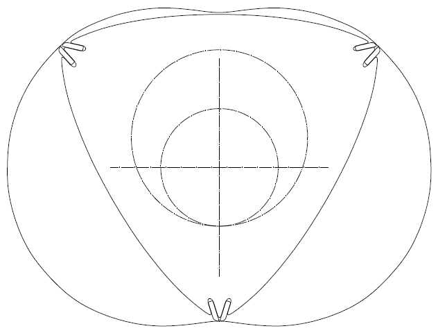
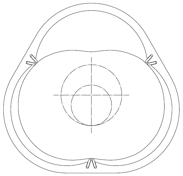
The converging of the grooves enables the two different seals at the specific apex of the rotor to abut closer to the geometrically correct point on the epitrochoid working surface (on one hand, this reduces the required motion of the seals inside their grooves in order to remain permanently in contact with the working surface on the casing, on the other hand, this reduces the "dead" volume, i.e. the volume between neighbouring apex seals).

With the following design each peak seal of a Reverse_Wankel / LiquidPiston engine relates with the combustion in one only working chamber.

PatWankel_iGR_13.gif


Among the advantages of the PatWankel_iGR design is the independence of the sealing of neighbouring chambers, also the elimination of the leakage towards the leading and trailing chambers: each seal seats onto the right side of its groove and uses the pressure in its own chamber to tightly abut on the working surface during the high pressure period of the cycle, i.e. as in the reciprocating piston engines.

Significant advantage is also that only the one face of each seal relates with high temperature gas; its other face abuts on the cool "bottom" of its groove; this way, the thermal load on the seal reduces substantially (the number of combustions it participates is half of those of a conventional apex seal), the mechanical stress of the seal is reduced substantially (there is neither bouncing of the seal among the flanks of the groove, nor slapping of the seal on the flanks of the groove when the one of the neighbouring chambers fires), the cooling of the seal is improved, etc.
All these improve the long-term reliability of the engine.

Here is a modified Wankel according the previous:

PatWankel_iGR_14.gif


Here is a PatWankel wherein the working surface is on the outer body (not shown). The inner body (actually the rotor) is sliced, with the one seal in place and the other two seals disassembled:

PatWankel_iGR_15.gif


Here ia another PatWankel wherein the working surface (whereon the seals abut and slide) is the external surface of the inner body:

PatWankel_iGR_16.gif


There are a few new animations explaining the previous.


Thoughts?

Objections?

Thanks
[FONT=&quot]Manolis Pattakos[/FONT]
 
Hello all.

Some animations and text have been recently added to the http://www.pattakon.com/pattakonPatWankel.htm web page:


In the following PatWankel, wherein each seal and each groove serve one only working chamber, the working surface (whereon the seals abut and slide) is the external surface of the inner body:

PatWankel_iGR_16.gif


Here is the inner body alone, with the three seals on it:

PatWankel_iGR_16A.gif


In the following drawing the two, of the three, seals have been removed.

PatWankel_iGR_16B.gif


The working chamber at left is at its TDC with its seal surrounding it and sealing it.
The inner body is like a "piston" pushed deaply into the working chamber (an unconventional piston that needs neither a connecting rod, nor a crankshaft).

At operation the "piston" (i.e. the inner body), remaining permanently in contact with the seal, is pushed outwards from the chamber and the volume increases, then the "piston" is pushed inwards and the volume decreases, and so on:

PatWankel_iGR_16C.gif


Every point of the inner periphery of the seal remains permanently in contact with the external surface of the inner body.

And if, instead of keeping the outer body (and the seals with it) immovable, the outer body is spinning at constant speed about a fixed axis (and the inner body with the working surface is also spinning at constant speed about another fixed axis), the elimination of the eccentric shaft comes with many other advantages:

PatWankel_iGR_16D.gif


Regarding the Wankel rotary engine:

Here is one of the worst problems the engineers of NSU and Mazda experienced several decades ago:

speed_bump.jpg


Confused?

No it is not the speed bumps on the roads.

It is the “speed bump” on the apex “road”, i.e. on the casing:

PatWankel_iGR_10.gif


Wankel_Apex_Seal_Acceleration.gif


Look at the “speed bump” at the lower and at the top side of the casing.

Look at the “reverse” centrifugal force an apex seal experiences each time it passes from the area between the two spark plugs (or from the anti-diametrically from the spark plugs are).

Have you ever passed over a “speed bump” with, say, 50mph (80Km/h)?
Did the car take off the road?

Imagine an apex seal taking-off the casing (at the “speed bump” area) and landing later, several degrees of eccentric shaft rotation, on the casing, bouncing a few times . If an RX-8 is forced to over-rev (say, braking abruptly with the engine) it cannot avoid such a problem.
The Wankel RX-8 requires strong springs under the apex seals, otherwise each apex seal will take off the epitrochoid twice per revolution around the casing.

Think the difference in the PatWankel wherein the inner body rotates at constant seed about a fixed axis and the outer body rotates at constant speed about is own fixed axis, which means constant magnitude of the centrifugal acceleration.

Thanks
Manolis Pattakos
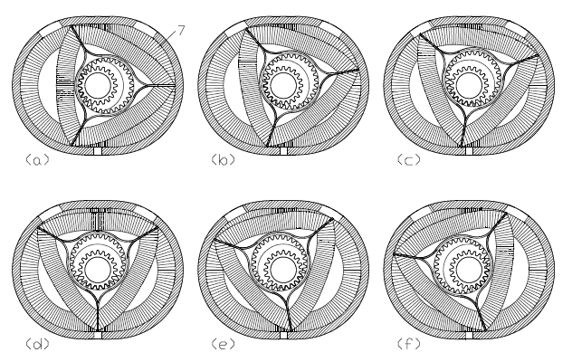
 
I think you are on the right track, but making the seal "rings" with enough precision will be challenging. I still think the problem area will be where the spherical outer surface transitions to the flat end of the inner body. I would be tempted to try to make an engine if I thought I knew how to make the one piece ring. I own an OS Wankel. It ran very well in model airplanes, but the expectations of fuel economy and engine life are much lower than in full size applications.

Lohring Miller
 

Latest posts

Back
Top