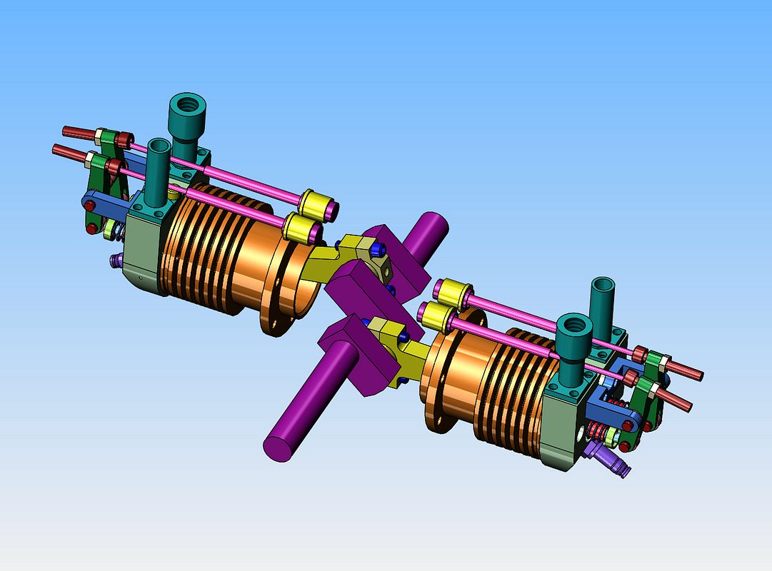
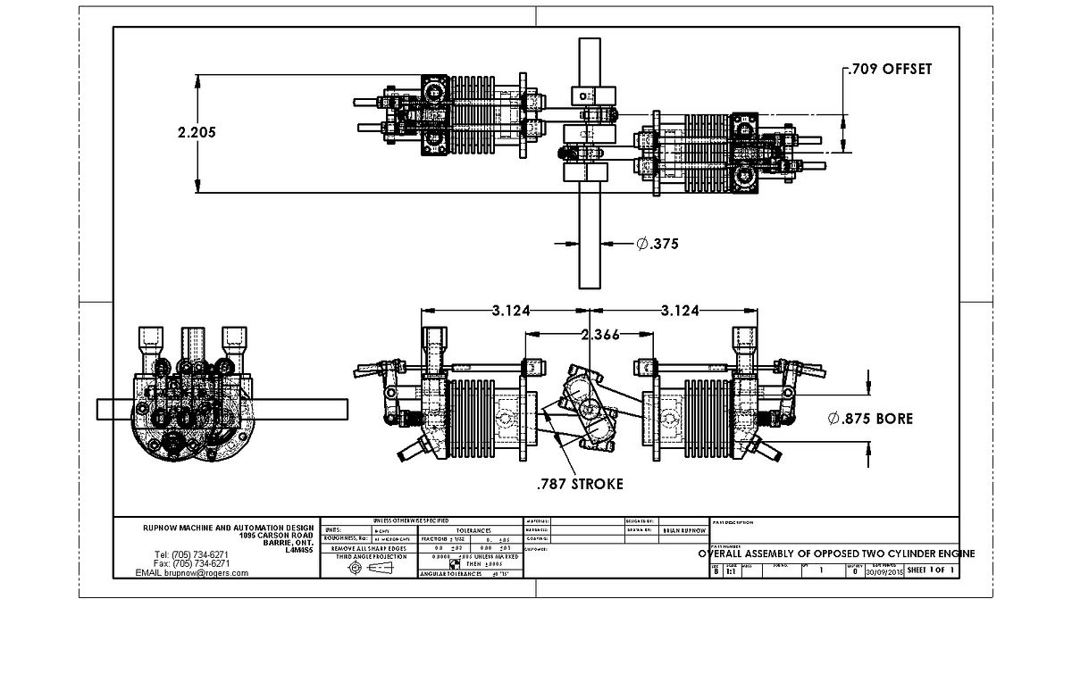
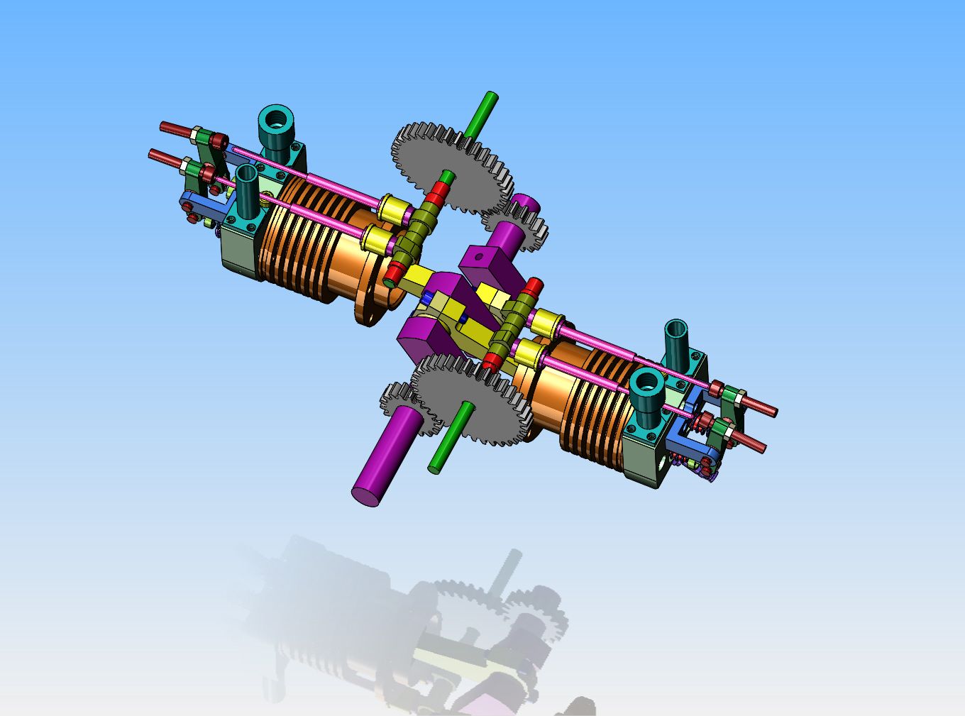
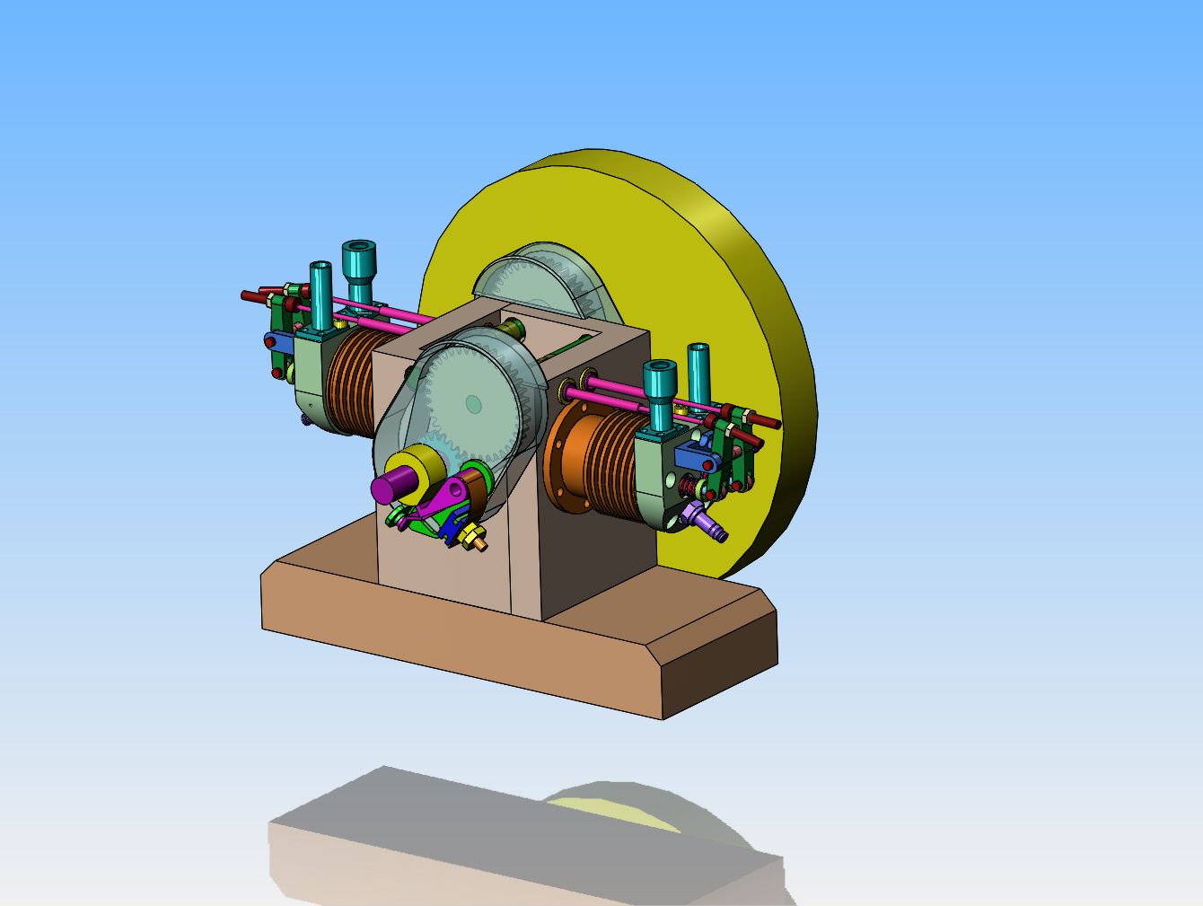
I woke up this morning, thinking about an opposed twin i.c. engine. something along the layout of Jason's flat twin Boxter, only a bit cruder perhaps, with an open crankcase and exposed camshafts and crankshaft. I really like the knife and fork style con rod layout, and the fact that it lets the opposed cylinders set in line with each other. I haven't really sorted this through in my head yet, but this would probably mean two camshafts, one above the crank to run the right hand cylinder and one below the crank to run the left hand cylinder.-----Or perhaps both camshafts above the crankshaft, offset to each side. A single centrally located carburetor with long intake runners to each side---maybe. I have to think on this a while.---It feels interesting----Brian
You are using an out of date browser. It may not display this or other websites correctly.
You should upgrade or use an alternative browser.
You should upgrade or use an alternative browser.
Opposed Twin I.C.
- Thread starter Brian Rupnow
- Start date

Help Support Home Model Engine Machinist Forum:
This site may earn a commission from merchant affiliate
links, including eBay, Amazon, and others.
dnalot
Project of the Month Winner !!!
Im jealous. I always wake up in the morning thinking about coffee and a bagel.
Mark T
Mark T
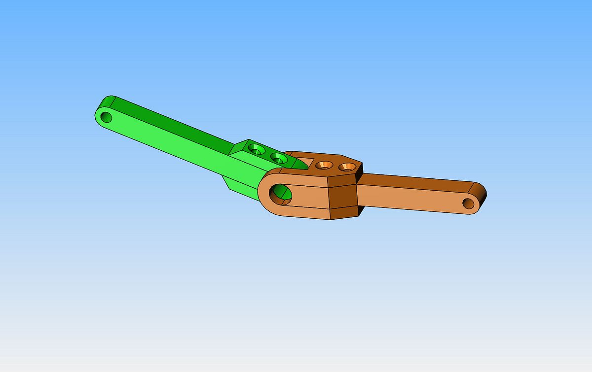
This is a new arrangement of connecting rod caps that I have just seen recently. I don't think it holds any real benefit except in a really small sealed crankcase, but it is certainly unique. The "knife and fork" arrangement of the rods lets you run two opposing cylinders in line with each other instead of having to offset them.

So---Perhaps we'll rethink this. I am being told that it's very bad juju to have opposed cylinders going to the same rod journal. I believe the folks who are telling me this. I wondered about it myself, but figured that if it wasn't a good idea somebody would speak up---and they did. I have enough problems with dynamic balance on my single cylinder engines without compounding it. So now--If the con rods go to seperate journals, 180 degrees apart, I can revert to the normal bolt on rod caps.
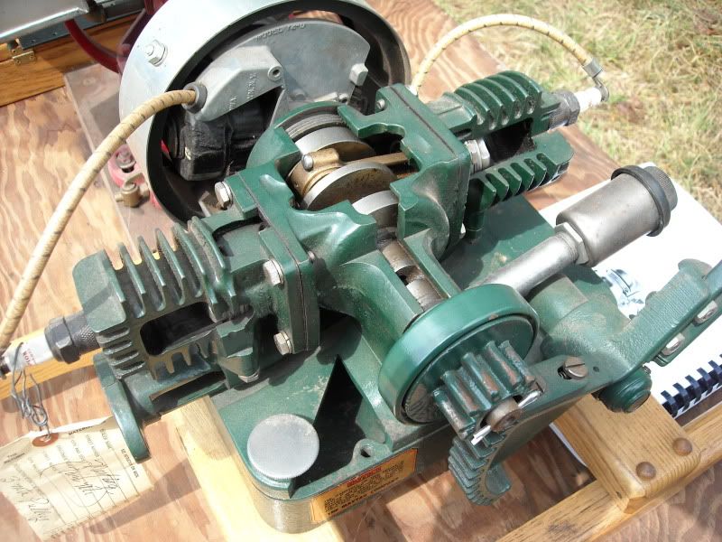
Having been told that "Maytag engines run smooth as silk." I think I will take a page from Mr. Maytags book and start this over again. It appears that the Maytag was a 2 stroke, but having found that there is some serious Voodoo involved with 2 stroke engines, I will be going with 4 stroke, overhead valves.

Last edited:

$156.90 ($1.40 / oz)
Replacement Combustion Chamber Kit, Burnham V8 and V8H, 1-6 Sec, 108136-01, 1129
Lynn Manufacturing

$403.09
DM14 Engine Build Kit, Metal Engine Build Model Great Metal Material for Engineer for Factory
Easoger Official

$190.00
$254.99
Genmitsu CNC 3018-PRO Router Kit GRBL Control 3 Axis Plastic Acrylic PCB PVC Wood Carving Milling Engraving Machine, XYZ Working Area 300x180x45mm
SainSmart Official

$39.99
$49.99
Sunnytech Low Temperature Stirling Engine Motor Steam Heat Education Model Toy Kit For mechanical skills (LT001)
stirlingtechonline

$15.99 ($0.05 / Count)
$18.99 ($0.06 / Count)
HongWay 300pcs 2 Inches Sanding Discs Pad Kit for Drill Sanding Grinder Rotary Tools with Backer Plate Shank and Soft Foam Buffering Pad, Sandpapers Includes 60-3000 Grit
HongWay US

$188.98
TM NEXDYNAMI RE41157 Water Pump Compatible With/Replacement For/John Deere 6200 7400 6300 6600 6500 6400 7220 7600 7200 RE41157
VIVID MARKET CORPORATION

$59.99
Sunnytech Hot Air Stirling Engine Motor Model Educational Toy Electricity Generator Colorful LED (SC001)
stirlingtechonline

$99.99
$109.99
AmTech300 - Boiler Treatment Professional Strength (Rust Inhibitor For Outdoor Wood Boilers)
Alternative Heating & Supplies

$649.00
$699.00
FoxAlien Masuter Pro CNC Router Machine, Upgraded 3-Axis Engraving All-Metal Milling Machine for Wood Acrylic MDF Nylon Carving Cutting
FoxAlien Official

$104.99
Sunnytech Hot Air Stirling Engine Motor Steam Heat Education Model Toy Kit M16-CF
stirlingtechonline

$28.51
$45.00
Key Contemporary Buildings: Plans, Sections and Elevations (Key Architecture Series)
Lions Den Books321

$45.99
Sunnytech Mini Hot Air Stirling Engine Motor Model Educational Toy Kits Electricity HA001
stirlingtechonline

$94.99
$109.99
AHS Woodmaster 4400 Maintenance Kit for Outdoor Wood Boiler Treatment
Alternative Heating & Supplies
Swifty
Well-Known Member
I'm already following along Brian, I was thinking about a horizontal opposed engine for my next project, not sure if 2 or 4 cylinder yet.
Paul.
Paul.
- Joined
- May 27, 2010
- Messages
- 2,999
- Reaction score
- 1,171
Brian,
Been waiting for this engine version. OK. I am following on.. Will build this engine too.
Been waiting for this engine version. OK. I am following on.. Will build this engine too.
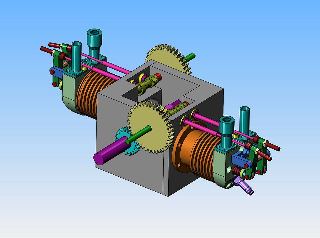
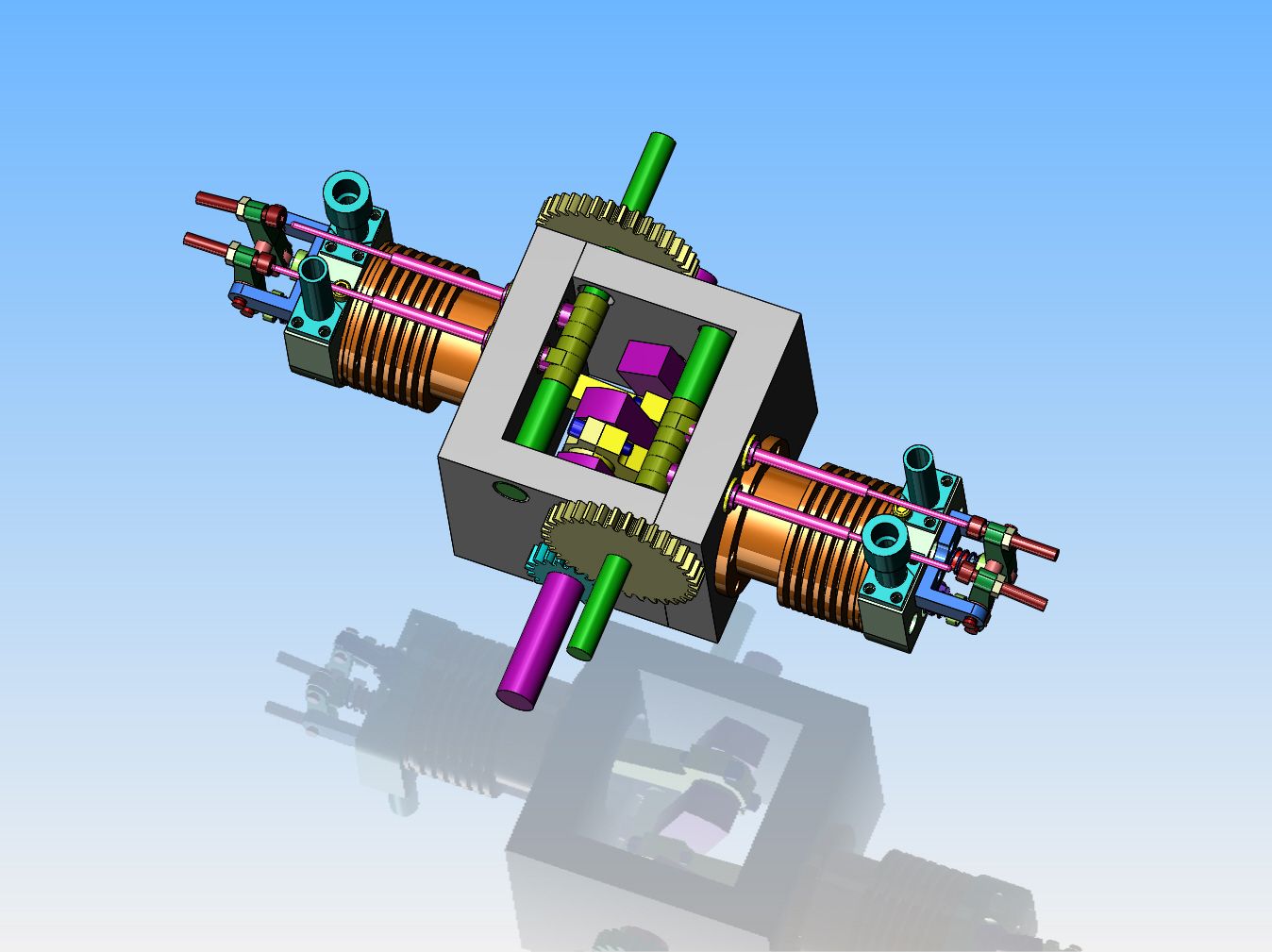
This is one of those rather unusual cases where, after massive amounts of cutting and carving and rearranging, everything seems to work just fine by bolting two pieces of 1/2" thick aluminum angle together toe to toe. Everything fits, clears, and seems to look surprisingly good. I did lengthen the connecting rods by 1/4" thereby moving the cylinders out 1/4" more from the center-line of the crankshaft to give myself a bit more room. I will make gear covers---Not so much as a safety factor, but as a noise dampner. Those meshing spur gears make a heck of a racket. It would be nice to machine the gear covers from clear Lexan so the gears remain visible but the racket is kept quieter. It appears that the two angles can be machined to finished size, bolted together and dowelled, then drilled and reamed thru both sides in one set-up for oilite bronze bushings for the crankshaft and both camshafts. The angles could then be unbolted to install the crankshaft and camshafts, then reassembled.

Brian, one thing to watch and that I still need to sort out on mine is that the crank tends to throw the oil into the right cylinder and oils it up so it does not fire so well. You can feel the exhaust gas from one cylinder is a lot colder than the other but when it does clear itself it romps away.
Either wants a curved baffle plate in the sump to lessen the amount of oil coming into contact with the crank or some thin plates either side of the cylinder opening in the crankcase to stop most of the oil getting to the bore.
This is why the inverted design may be better as the cams won't throw up as much oil and the plugs will be at the top of the heads not the bottom so won't be affected by flooding.
Jason--My intent all along has been to run this thing open crankcase---no top on it. Drill oil galleries down thru from the top to the crankcase and camshaft bushings and just give the cams and con rods a squirt of oil on start up. This engine will never see long duration runs nor heavy service. I want it to run slowly and use a 6 inch diameter flywheel as shown with vanes cut into the outer inch to act as a fan to blow on the cylinders to cool them. This makes for a rather strange looking base but I need that much height in the base to get flywheel clearance.
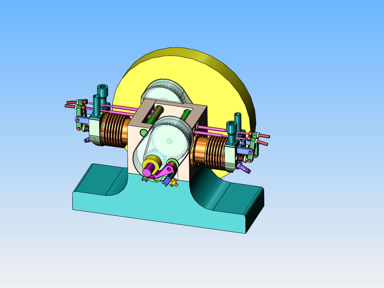

So---This is what I would like to do with the flywheel. The flywheel is 6" maximum outer diameter overall x 3/4" thick, made from either brass or mild steel or a combination of the two. The outer band is 1/8" thick The "blades" as I have shown them are 3/16" thick. The outer diameter of the main flywheel body is 4 1/4", and the bore is 3/8". The recess shown in the sides of the flywheel is somewhat irrelevant (I know how to do that.) Now remember--This is a "best case" scenario". I do not have the capacity to machine it from solid. I do have the capacity to cut 3/16" wide slots x 1/8" deep in the outer diameter of the main body to act as "positioners" for the 8 "blades", but the body would soak up so much heat that it would be a real bear to solder the blades in place as individual entities, and that leaves me having to solder or bolt the outer rim into place.--I want the flywheel to be concentric---I hate flywheels that look like they are "orbiting" the crankshaft. I could probably even use #2-56 s.h.c.s. to bolt the blades on, but that's a lot of tapping with a fairly fragile tap. (The head on a #2-56 shcs is small enough to bury in a counterbore in the 3/16" wide blades.) I'm open for suggestions!!--Brian
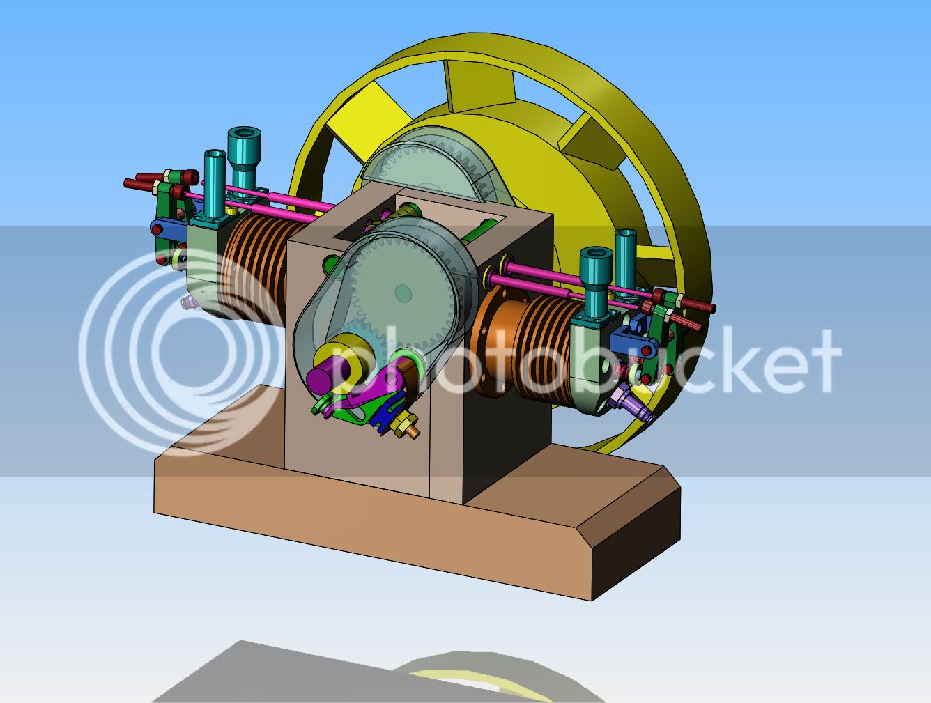
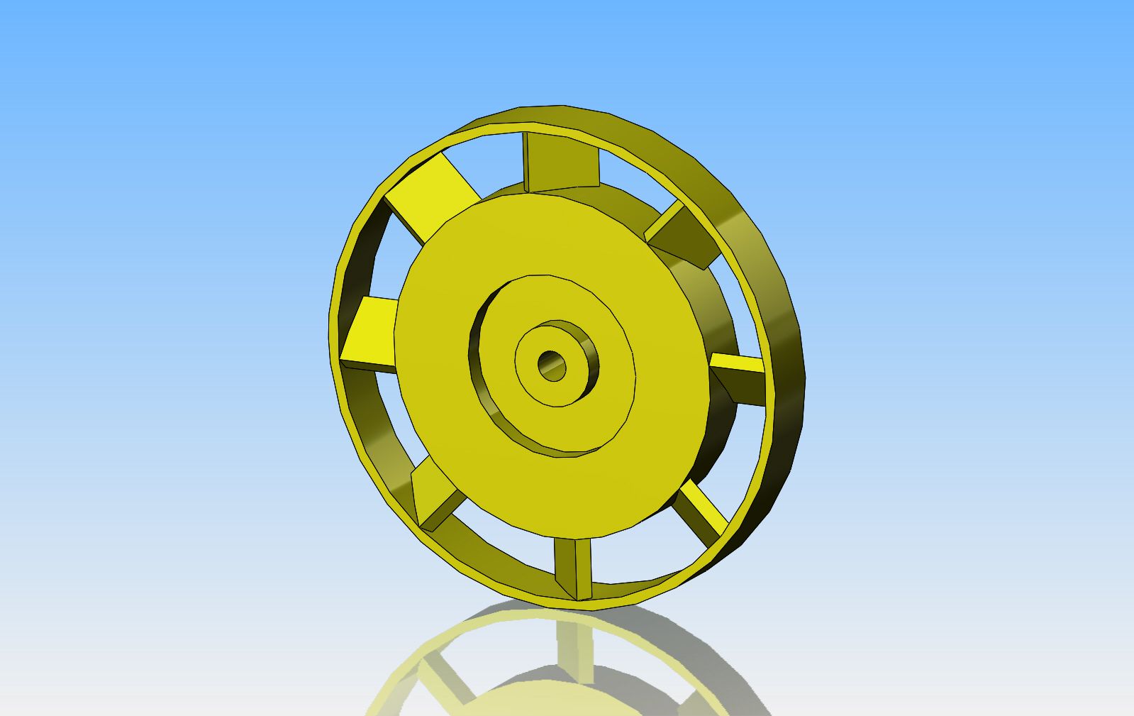


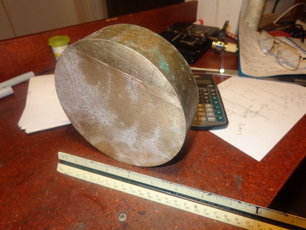
I have one last piece of bronze left from the government scale checking weight that I was given a couple of years ago. It measures 5 3/4" diameter x 1 5/8" thick. I am so intrigued by the "flywheel with cooling vanes" that I may try to make the flywheel first. 
 I will have to cobble up some method of slicing it in half. The guy I buy my steel from has a giant bandsaw that he has been using to slice of 1" lengths of this thing for me to make flywheels from, at $10 per slice, but it is now to thin to hold in his saw vice.

You mention using dowels for the crankcase halves. The halves will have to be brought together in the direction of the crankshaft axis, but your joint lines are in the wrong orientation for this: the dowels would have to be removed to get the thing apart. By having the joints at right-angles to where you have them, the dowel axis can be in the direction of assembly. You would also need to move the joints to the opposite corners so the cylinder flange does not lie over the joint.
Swifty
Well-Known Member
Brian, can an angle plate be held in the bandsaw and the slug clamped to it, cut it halfway throw and reverse.
Paul.
Paul.
Similar threads
- Replies
- 61
- Views
- 12K
- Replies
- 31
- Views
- 5K


