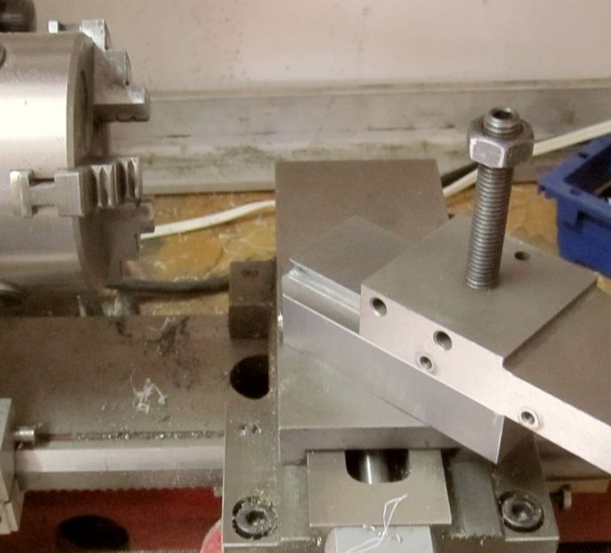
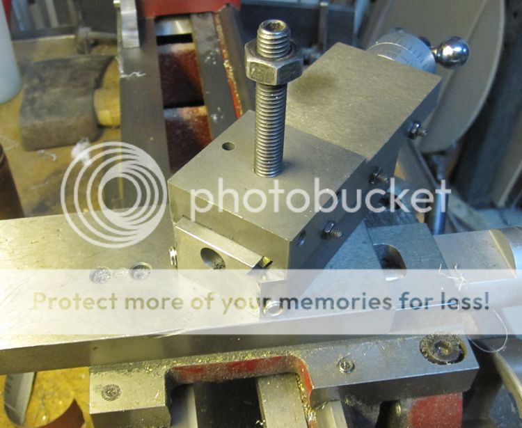
New Minilathe Compound

Home Model Engine Machinist Forum

Help Support Home Model Engine Machinist Forum:

This site may earn a commission from merchant affiliate links, including eBay, Amazon, and others.

cfellows

Well-Known Member
Project of the Month Winner
Joined
Aug 25, 2007
Messages
3,890
Reaction score
715
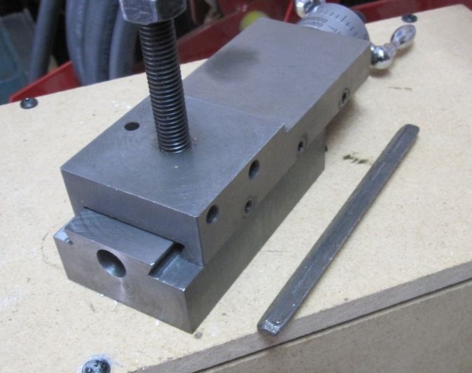
The compound on the standard 7 x 10/12/14 minilathe sucks. Having to crank the compound all the way back each time you want to change the angle is just miserable and for that reason, I usually don't have the compound mounted on my lathe. But, I do need a compound from time to time and I've finally decided to see if I can come up with something better. Here is the existing base of the included minilathe compound. I have modified mine, drilling a second set of mounting holes and shaving 3/16" off the bottom to lower the profile.
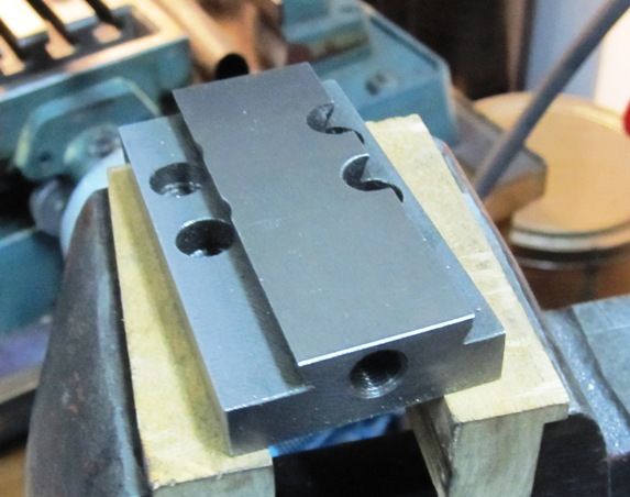
IMG_3463_zpsfcc9495e.jpg


I considered making the new base from either aluminum or brass, since I have those materials on hand, but I really wanted to use cast iron. The only cast iron I had was a round bar 2 1/16" diameter about 3 1/2" long. So, mounting it up I the mill, I started whacking away with my face mill. Here I've go one side milled down to size.
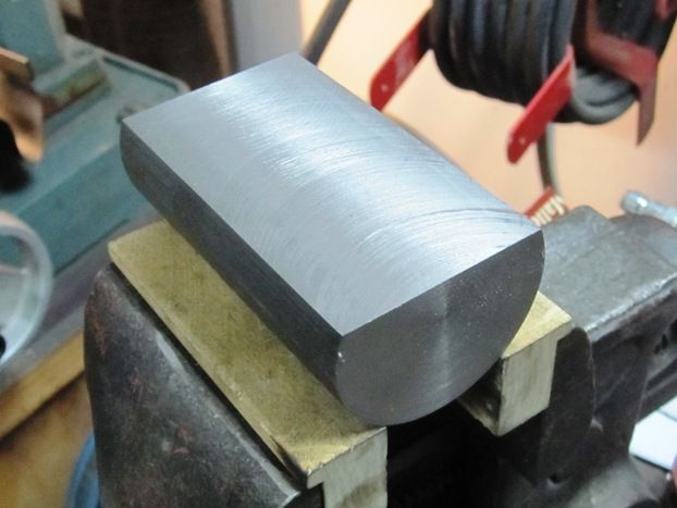
IMG_3462_zps60a4b5d7.jpg


And here I've whittled down the two sides, also to size.
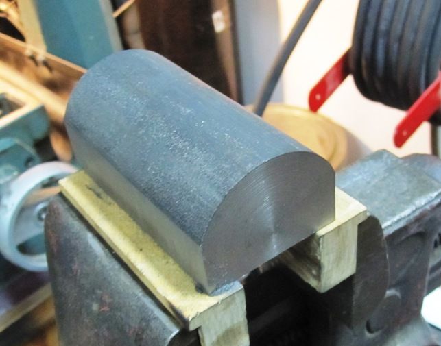
IMG_3464_zpse8880f50.jpg


Next I'll finish cutting the top down to size and continue with the dovetail shaping. The new mounting will use screws coming in from the side to clamp against an inverted, cone-shaped piece.

Chuck
 
Sounds like a good idea.


Sent from my iPad using Model Engines
 
The compound on the standard 7 x 10/12/14 minilathe sucks. Having to crank the compound all the way back each time you want to change the angle is just miserable and for that reason, I usually don't have the compound mounted on my lathe. But, I do need a compound from time to time and I've finally decided to see if I can come up with something better. Here is the existing base of the included minilathe compound. I have modified mine, drilling a second set of mounting holes and shaving 3/16" off the bottom to lower the profile.
The compounds on the 9x20's suck too. Like you I've removed the compound, mounting it only when needed. In this case not because of accessibility so much as needing a good way to mount an AXA tool post.
I considered making the new base from either aluminum or brass, since I have those materials on hand, but I really wanted to use cast iron. The only cast iron I had was a round bar 2 1/16" diameter about 3 1/2" long. So, mounting it up I the mill, I started whacking away with my face mill. Here I've go one side milled down to size.
All of that castiron turning into swarf has put tears in my eyes.
And here I've whittled down the two sides, also to size.


Next I'll finish cutting the top down to size and continue with the dovetail shaping. The new mounting will use screws coming in from the side to clamp against an inverted, cone-shaped piece.

Chuck


On many old lathes an eccentric was used to clamp the compound. I'm not sure if this is you intention or not but it is one approach. What I really find interesting though is what does this do for the overall height of the compound. In the 9x20 the compound is just a bit too high for the AXA tool post.

Keep up the good work Chuck, your post inspire.


Sent from my iPad using Model Engines
 
Thanks, Wizard! I hated to waste all that cast iron, but even if I had band-sawed to shape, I'm not sure the left overs would have been useful. I had thought about using some kind of eccentric, like many people have done on their tail stock clamps, but decided to use wedged rods held in by set screws coming in from the side, like the Logan (and I think Southbend) uses.

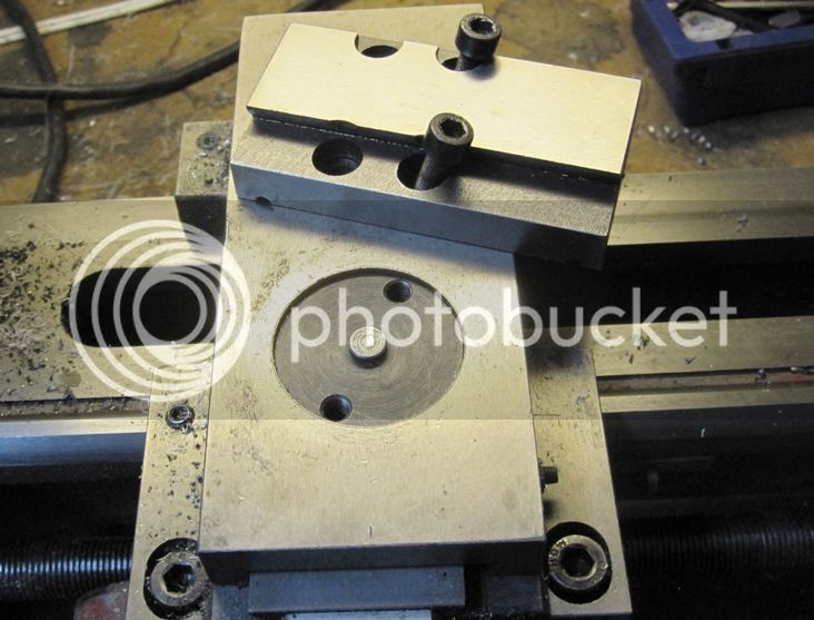
Just for clarification, for all the folks on the forum, here's a picture of the current compound base and cross slide configuration:

IMG_3465_zpse70fd137.jpg


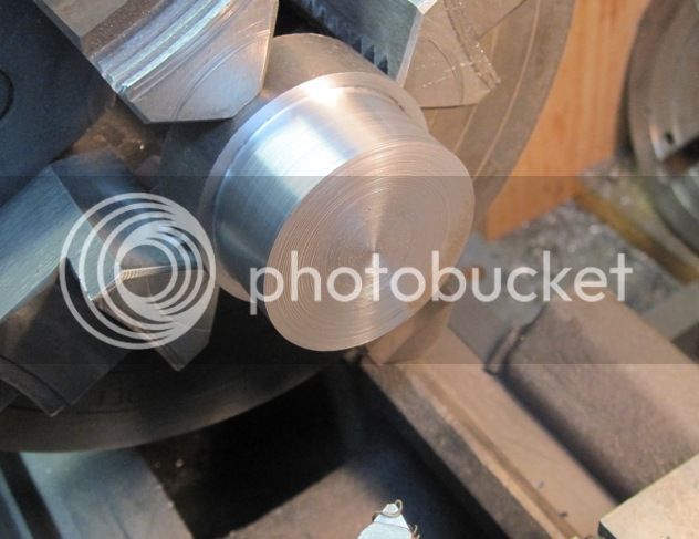
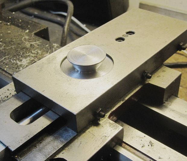
Today I made the spigot that will secure the base to the compound in the future. I started with a piece of 2" CRS and turned down the end to 1.75" which is the OD of the existing clamp down piece.

IMG_3466_zps3a19abc4.jpg


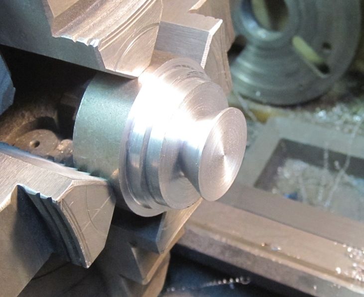
After further shaping, it winds up looking like this. The taper is cut at 30 degrees to the axis.

IMG_3467_zps1f2d643a.jpg


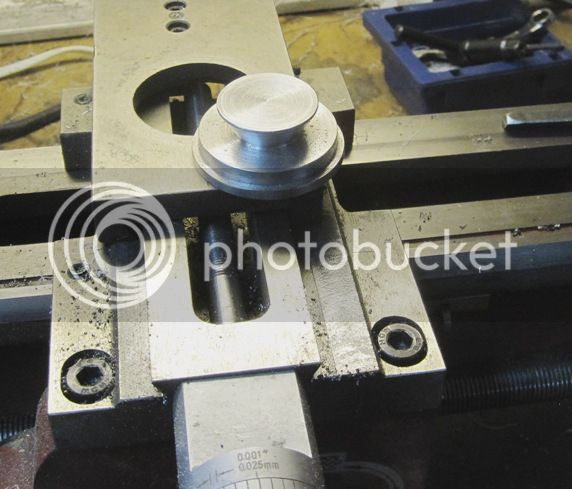
Here's the parted off and finished spigot sitting on the cross slide...

IMG_3468_zps0885e169.jpg


And here's what it looks like installed in the cross slide.

IMG_3469_zps5e94c152.jpg


It rests a bit lower than it will when pulled up tight while securing the compound.

Note that no modification to the cross slide was required. And the old compound base can be left as was while not being used.

Chuck
 
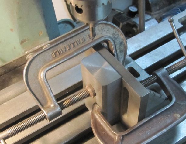
Here is the compound base milled to overall dimensions. I've got it mounted on my milling table so I can drill the hole for the feed screw.

IMG_3471_zps4fe3d3f3.jpg


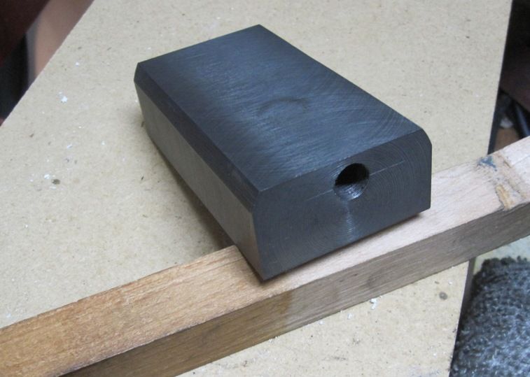
And here's the piece with the feed screw hole drilled and tapped M10 x 1. The hole is counter-bored from the back to a little over 10mm so only about the first 20mm actually have useable threads.

IMG_3472_zpsc6d95d00.jpg


I'm wasn't real confident about my ability to locate and drill the feed screw hole and get it exactly right in relationship to the position of the compound top, so I decided to drill and tap it first. Then I can adjust the position as needed later when I cut the dovetail. I'll try to sneak up on it so I don't get any binding.

Chuck
 
A little similar to the method Taig uses.


Sent from my iPad using Model Engines
 
Good solid looking design. Nice work.


Sent from my iPad using Model Engines
 
Man you are working fast here. Apparently you are a man of action.

The more I read about the little 7 x XX lathes the more respect I have for them. It is rather neat how they dealt with compound mounting on this small machine and how easily you adapted to it.


Sent from my iPad using Model Engines
 
Thanks, guys. Being retired, I have a lot of hours available to dedicate to this stuff. I like to keep busy, don't know how many years I have left... :rolleyes:

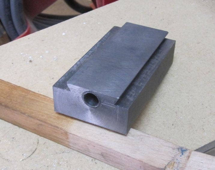
So, I got the dovetail finished. I managed to hit it right on the first trial fit, which is a little scary, because I was trying to get it oversize and make several more passes to get a perfect fit. Oh, well, can't argue with success.

IMG_3476_zpsf2f26fa4.jpg


And here it is with the compound in place...

IMG_3477_zps6fc467a4.jpg


I'm going to make a new GIB for it since I don't care for the 1/4" thick GIB which came with the old base. I made the dovetail on my new base about 1/8" wider so I can use a 1/8" thick GIB.

Chuck
 
One more picture for today.

IMG_3478_zps2d214d0d.jpg


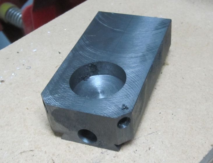
I finished the cavity on the bottom and the two, 45 degree holes that will hold the clamping rods. The holes will accept 1/4" diameter rods with a 60 degree wedge shape on the end. The outer portion of the holes will be threaded for 5/16-18 set screws. I had to stop work on it tonight because the only 5/16" tap I have is miserably dull! Off to buy a new one tomorrow!

The new base will make the compound about 3/16" higher than the original. Not too bad a trade off in my estimation.

Chuck
 
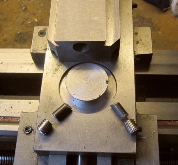
I got it finished and installed today. Here's a picture of the parts and their arrangement.

IMG_3479_zps8f26e4b6.jpg


Heres the base installed on the cross slide.

IMG_3481_zpscbffb8c7.jpg


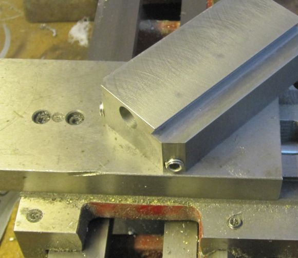
The compound slide is just sitting on the base in this photo

IMG_3482_zps7aaf1897.jpg


And here it is with new brass GIB installed and everything ready to go...

IMG_3484_zps08735781.jpg


I have about 3/4" between the top of the compound and the spindle axis. I think that will be more than enough for me and I could probably shave 1/8" or so off the top of the compound slide to give me more room if I needed. If I had it to do over again, I could probably find a way to shave 1/8" off the height of the base. As it was, I used 5/16" set screws and 1/4" rod which is more beefy than needed, but the good news is that compound is rock solid with the parts used. I'm very happy with the results.

Chuck
 
Wow, Chuck! That is a fantastic modification. Having only a MicroMark 7x14 lathe, I know what a pain it is to change the compound angle. Great work, sir!

Todd
 
Back
Top