Hello from my little island at the very west of France
Its time for me to describe building of Wyvern from Edgar T. Westbury the famous model Engineer, a star for me.
At the beginning of this month, I decide to buy the complete kit and draws from Hemingway Kits. Very good contact with a serious seller and short shipping time to my island.
After opening the parcel, I have noted the quality of casting and the packaging.
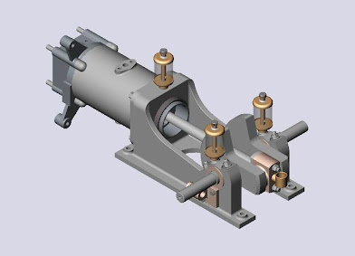
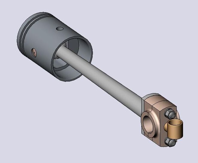
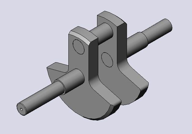
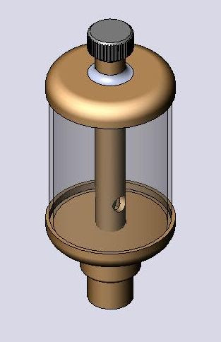
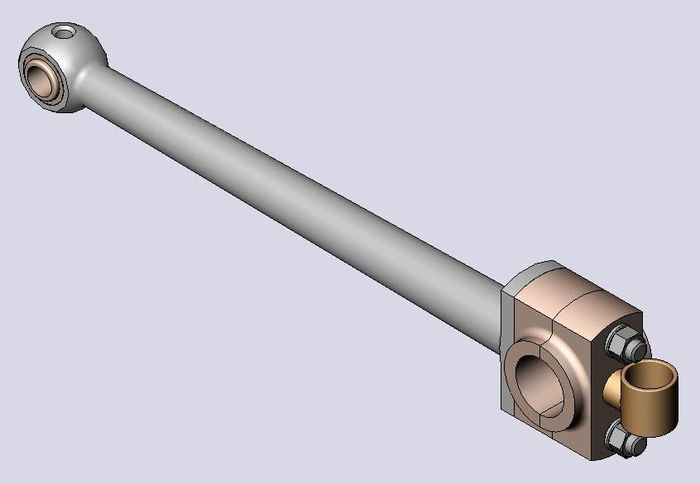
As Im French , I must convert Imperial to metric before machining parts and simulate assembly with SolidWorks to confirm.
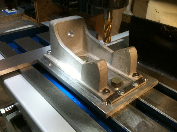
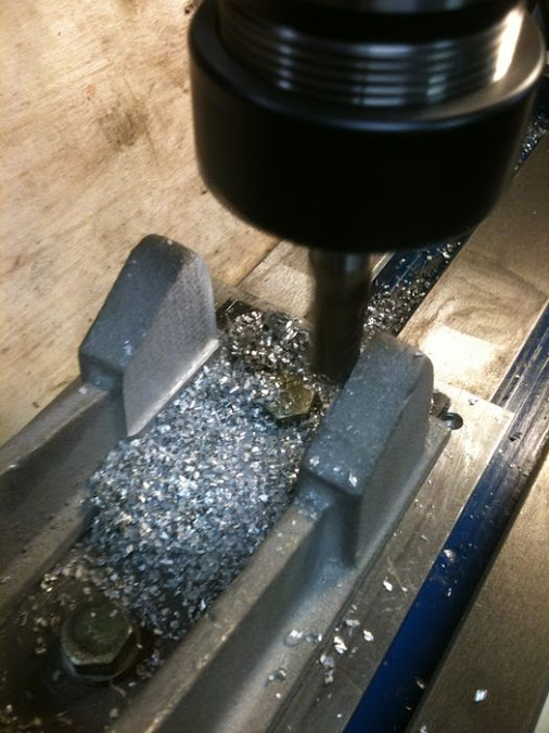
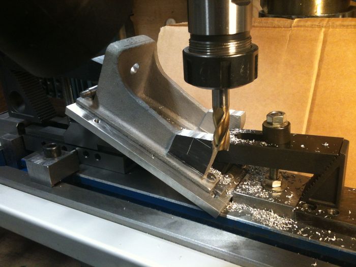
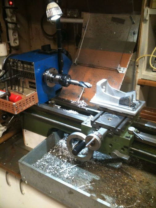
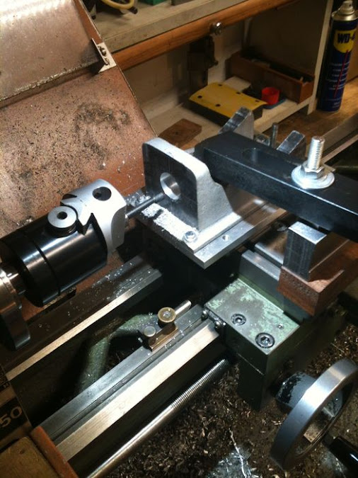
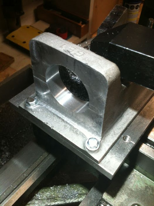
I began by the lower side of the sub-base
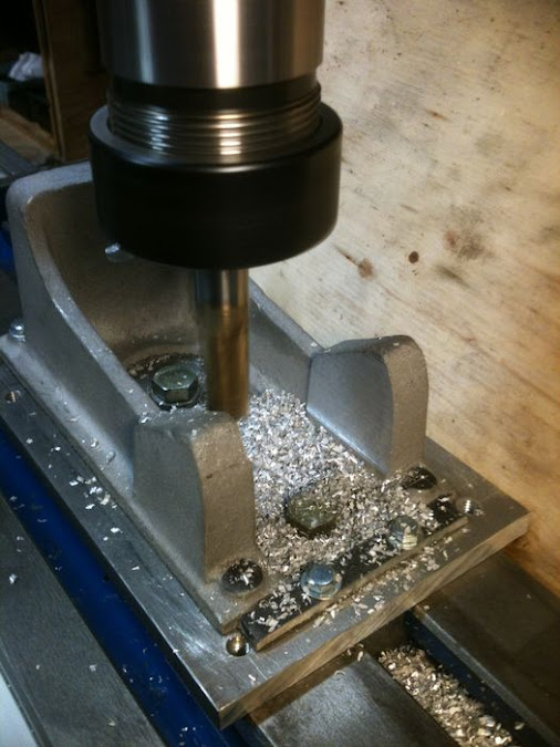
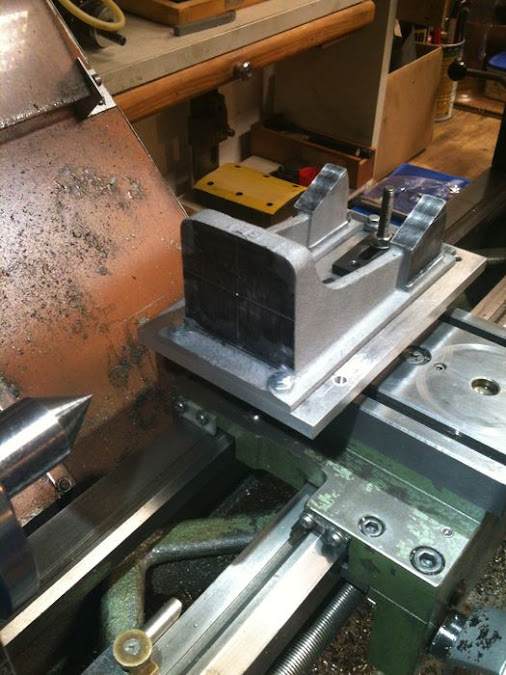
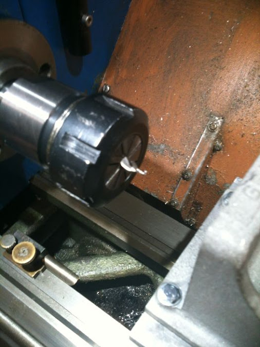
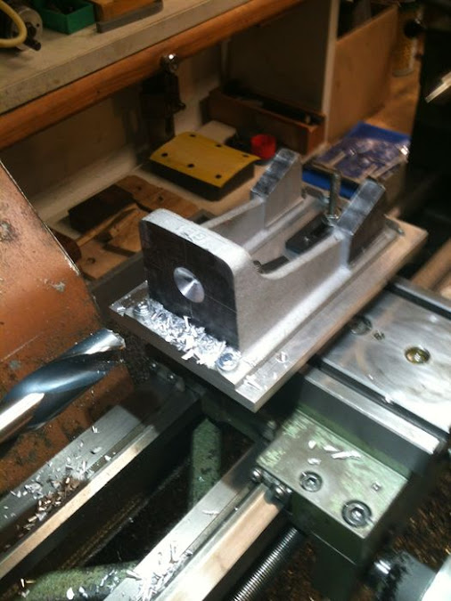
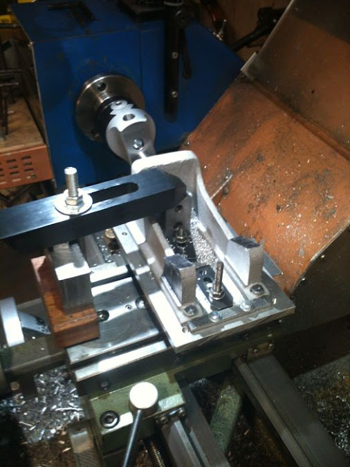
Following, the main bed
Didier


Its time for me to describe building of Wyvern from Edgar T. Westbury the famous model Engineer, a star for me.
At the beginning of this month, I decide to buy the complete kit and draws from Hemingway Kits. Very good contact with a serious seller and short shipping time to my island.
After opening the parcel, I have noted the quality of casting and the packaging.
As Im French
I began by the lower side of the sub-base
Following, the main bed
Didier






![MeshMagic 3D Free 3D Modeling Software [Download]](https://m.media-amazon.com/images/I/B1U+p8ewjGS._SL500_.png)


![DreamPlan Home Design and Landscaping Software Free for Windows [PC Download]](https://m.media-amazon.com/images/I/51kvZH2dVLL._SL500_.jpg)


![TurboCAD 2020 Designer [PC Download]](https://m.media-amazon.com/images/I/51UKfAHH1LL._SL500_.jpg)


