My design, 4 cylinder overhead valve engine

Home Model Engine Machinist Forum

Help Support Home Model Engine Machinist Forum:

This site may earn a commission from merchant affiliate links, including eBay, Amazon, and others.

gbritnell

Project of the Month Winner!!!
Project of the Month Winner
Joined
Jul 16, 2007
Messages
3,023
Reaction score
1,098
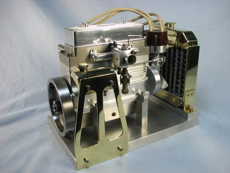
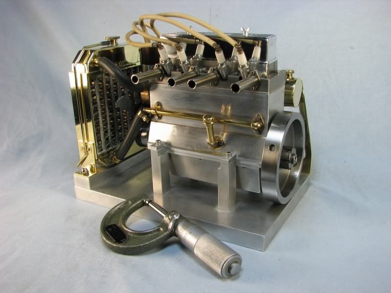
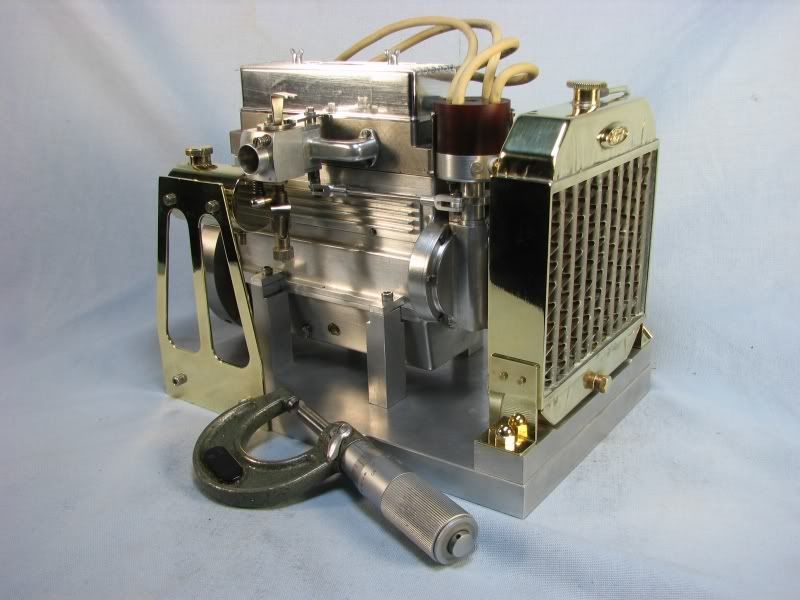
Gentlemen, I am getting my engines ready for a show this October in Zanesville, Ohio. I haven't run my 4 cylinder engine in quite awhile so after going through it, cleaning plugs, resetting timing, adjusting advance mechanism, etc. I thought I would post a few pictures. You can see the general size of the engine by comparison with the micrometer in the picture. It has a water jacket around the cylinders with a water pump. It has a point/spark ignition with home made spark plugs, the reach is longer than what is available. The oil system is splash. I usually put a few drops on the valve train before running it. The bore is .625 and the stroke is .750. The radiator top and bottom tank was made with a die and it put some wrinkles in the brass but not too bad. There are 3 rows of .125 tubes and the finning was made from strips of brass. I cut the strips, tinned them and then formed the shape over a fixture made with small pins in a board. These were then fluxed, slid between tubes and then soldered with a propane torch.
gbritnell
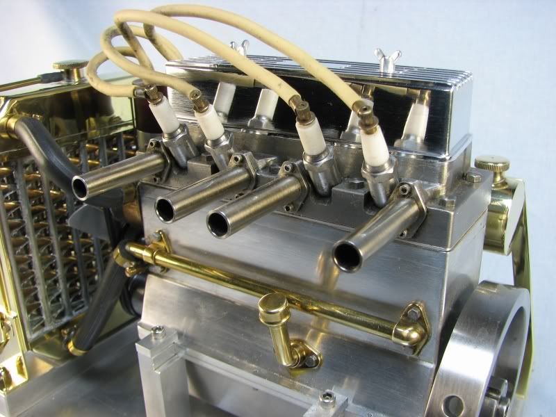
4cyl1.jpg

4cyl2.jpg

4cyl3.jpg

4cyl4.jpg

4cyl5.jpg


:bow:RESPECT:bow:

Nice piece of work. Can you post a small video of it running?
 
that is a very clean looking design - nice work!

have you made plans available?
 
gbritnell,

What a really nice engine! I would love to know more about your design process. I also would like to see it running. I do like the valve train, especially the rockers. Please tell us more!

Mike
 
Crap, now I'm going to have to start dressing up my rocker arms to look more like yours and less like little chunky blocks of metal!

Seriously, that's a fine looking engine. I really admire your work. How did you make the intake manifold?

Chuck
 
A bit off topic but do you have a link to details on the show in Zanesville? I'd like to come down and see it in person!
 
Thank you for the gracious comments. To answer some of your questions: here is a link to the show in Zanesville, Ohio.
http://deboltmachine.com/_wsn/page13.html
Next, the intake manifold was made from one piece. I drilled the long runner from one end and then plugged it and contoured it to shape. Although the manifold looks strange having only 2 connection points that's because the intake ports are siamesed at the port face on the head. When I designed it I thought that the flow would be more uniform it it didn't have to run out too far so I kept the ports an even distance out from center for each cylinder.
Next, I haven't made complete plans for it but I would like to do that this coming winter. When I do I will let everyone know.
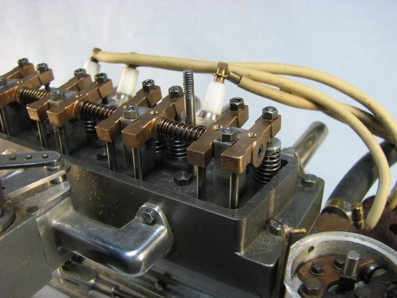
Next, Mike, did you have questions about the valve train in particular or just the engine in general? A few things I can tell you are: 1. When you make an engine this small you can't scale the flywheel down with it. The flywheel needs enough centifugal weight to get the cylinders over the compression stroke. 2. It helps to have some type of advance system for the ignition, not just on this engine but any engine with a wide range of rpm's. This engine was somewhat easy as the carb is in a position to run a linkage to the distributor. I start the engine at about 7-10 degrees of advance and when it revs up I can get about 25-30 degrees. 3. The pistons have 2 compression rings. I made them per the Trimble design and they work very well, so well in fact that as they seated in I had to put a spacer plate between the block and head to reduce the compression. I originally designed it at about 8:1 compression. 4. The block is aluminum with iron sleeves. The head is iron. The valves are stainless steel. The crank is 1018 crs. The rods are bronze. The crank has bronze split inserts at the main bearings. The cam is oil hardening drill rod although it's not hardened. The lifters though are hardened. The distributor is driven by a pair of bevel gears off of the end of the camshaft. The points have tungsten tips that I took from a set of motorcyle points and then ground them to the required diameter.
The rocker arms are bronze, with the adjusters made from drill rod and hardened where they push on the valve stems. The spark plugs have mild steel bodies with a ground strap machined onto the end. The insulators are virgin grade teflon.
As far as a video, I will be running it next week and should be able to get a short clip at that time. I will post it as soon as I get it.
gbritnell

 
Gbritnell,

Well, you have just caused an argument in my house, I spent 1 1/2 hours looking at the pictures and totally forgot that it was my turn to make dinner ;D ;D ;D

Seriously nice work, particularly interesting is the spark advance/retard, is it a fixed linkage? How did you come up the the ratio for the linkage?

In most engines I know the ignition is advanced mostly under load by a vacuum and a little by a centrifugal mechanism (or vice-versa) in the dizzy, do you get any pre-ignition at higher revs?

Cant wait for the video of it running.

David

 
GB that's not just an engine ............ it's a work of art 8) :bow:

Absolutely lovely ............. I too look forward to the video ;D

CC
 
One of the butyest I've ever seen. Nice work :bow:
We are waiting for plans ::)
Regards
CS
 
Hi David. As for the linkage ratio, I calculated how much I would need to move the distributor to get the required advance and with the link on the distributor that I made, how far it would have to rotate. I then drew up a bell crank type of linkage for the carburetor and made the actuator arm a little longer than the one on the distributor, figuring I would allow myself more travel than needed and adjust accordingly. When it came to timing I first connected the 2 arms with a link and with the carb at an idle or low speed postion I rotated the distributor (with the link a little loose) until my points just opened at approximately 10 degrees. I then tightened the arm on the dist. I then opened the carb wide open and checked my timing to see where it was. Most naturally with the greater ration from the carb. to the dist. I got more timing than I needed so I rotated the arm on the carb so that I was working away from the direct 90 degree postion (max travel) until the amount of travel/movement would give me the span of advance I needed. I had to keep adjusting the length of the linkage so that the initial dist. setting wouldn't change. As far as pre-ignition, I can't really tell if it exists. The engine revs cleanly, within the limits of the air bleed type carb. I did my calculations on full sized engine practice for the timing and with the smaller combustion area I figured it would be in the ballpark.
gbritnell
 
Beautiful Engine gbritnell!

Rick
 
That completely blows me away! A complete running OHV engine less than 4" long?!?!?

Wonderful work gbritnell, thanks for the inspiration.
 
gbritnell That is absolutely bloody fantastic i wish i could be in ohio too see it run,a brilliant achievement
Regards Max...........
 
Thanks again to everyone who has responded since my last posting. For anyone in the Ohio area I will have this and other engines at the Zanesville, Ohio engine show later this month.
gbritnell
 
Now my wife works very hard and I think she deserves a little time away.
I've offered her a weekend trip to Zanesville Ohio.

If she falls for it, and all other issues permit, I hope to be there to see
your engines in person.

Rick
 

Latest posts

Back
Top