Moteur Oscillant - Double acting Oscillator Twin

Home Model Engine Machinist Forum

Help Support Home Model Engine Machinist Forum:

This site may earn a commission from merchant affiliate links, including eBay, Amazon, and others.

cfellows

Well-Known Member
Project of the Month Winner
Joined
Aug 25, 2007
Messages
3,890
Reaction score
715
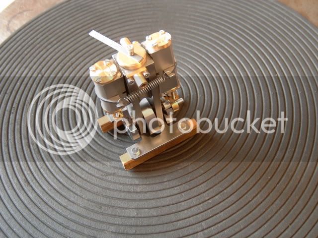
I've tabled the Rudy Kouhoupt twin marine engine for the moment and started on the French designed Moteur Oscillant. Stew Hart and Bogs have both built excellent versions of this engine and I think it might be suitable for a boat or land vehicle later down the road.

Here is a link to the original plans:

http://jpduval.free.fr/Moteurs_vapeur_simples/MV%20deo%2010x20.pdf

I have increased the size by about 10% and converted all the measurements to inches. My engine will have a 7/16" bore and 7/8" inch stroke. I opted to use aluminum since I had a large piece the right size and I wanted the engine to be as light as possible, especially if it winds up in a boat.

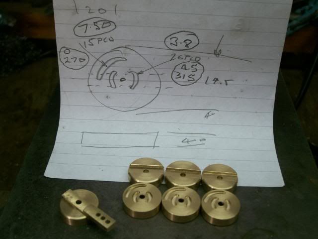
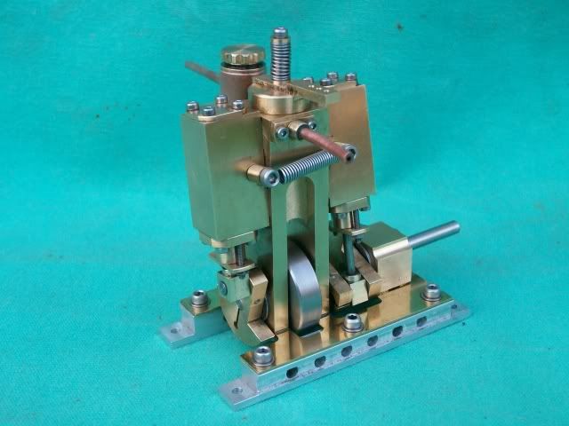
I've got the frame and cylinders, pretty well finished. I've also finished both cylinder end caps except for the mounting holes. Here's a few pictures of the work so far. If you look closely at the first picture, you can see a small o-ring nestled in the middle end cap piece.

f0e562f5.jpg


f76882f9.jpg


e9511c22.jpg


Chuck
 
Hi Chuck

This engine is a great design.

I'm not sure however if it will be a good idea to use aluminium for both the cylinders and the engine housing, I'm affraid the two parts will fuse together

DX330060.jpg


Chuck,

I am not trying to teach you to suck eggs, but I too am a little worried over your use of ali.

I have made a fair amount of these engines in the past, and also passed over the modded versions of the engine to Stew so he could make a batch of them for sale.

My main worry is when it comes to run on steam. It will be good on air, but the heat produced when steaming changes the whole characteristics of how the engine operates.

The plans do have a bit of a flaw in them. If you make the control disk on the top as per the plans, the operating lever sits over one of the cylinder tops, you need to move the lever groove so that it sits to the side of the main frame when in operation.

My two versions of the same engine showing the modified spring arrangement which makes it a lot simpler build

6.jpg


John
 

The plans do have a bit of a flaw in them. If you make the control disk on the top as per the plans, the operating lever sits over one of the cylinder tops, you need to move the lever groove so that it sits to the side of the main frame when in operation.

You just have to move the slots round 45 deg, on Johns recomendation I also added a groove for a stop pin.

Like this

100_4384.jpg


100_4490.jpg


I'm not to sure about the use of ally also.

Why are you concerned with the weight from my limited understanding weight is added to a boat to give it trim.

They do build up into a very nice engine though.

One other area you may concider changing is the crank webs pinched onto the shafts, after building I though that it may have been better to use small 2mm grub screws to fix the webs, may well be worth doing a little experiment with this.

Hope this helps

Stew

 
Hi Chuck,

Looking good. I don't know whether aluminium is good for making the cylinders and port block as far as wear and lubrication go, I have never tried it. I have used aluminium to make pistons in brass or bronze cylinders where it works very well. So I suppose a brass piston in aluminium cylinders would work the same? I wouldn't worry about the engines weight, in all the boats I have fitted steam engines to have had to have ballast added to them.

Regards Tony.
 
Hi Chuck, workmanship up to your usual high standard I see! are those ball bearings I see in the main bearings? and is the central frame laminated from three pieces?
As to materials, I was always told that sliding friction between similar metals is never a good idea (except cast iron ofcourse) but aluminium seems to get on pretty well with steel and most non ferrous metals, like in alloy master cylinders with steel pistons and ofcourse aluminium valve bodies with steel pistons in auto transmissions. Your sheer output of projects always amazes me Chuck.
regards Stew
 
I built Elmer's reversing wobbler...

wobbler1.jpg


using aluminum for the cylinder and standard. The first time I ran it (on air) it seized up to the point where I couldn't rotate the cylinder using my hand. After separating the two parts and redoing the surfaces, I lubricated the interface with Neverseize and now it runs fine on air (I've never run it on steam).
 
Thanks, everyone, for the comments & compliments.

Bogs, yours was the first example of this engine I saw and liked both your versions immediately. I had decided I wanted one someday.

m_kilde, what are your frames and cylinders made of? They don't look like brass? Nice looking engine. :bow:

Stew (sbwhart), I saw the video of your engine running and liked the way it ran and sounded.

Stew (compspecial), those are flanged ball bearings in the frame. I'm a little concerned that they may not be stainless and might pose a problem at some point. The frame is carved out of one piece. As to the volume of my work, well, I'm retired, so I have a lot more time. I also work pretty fast which results in lots of mistakes and re-do's. I'm trying to slow down and be more careful! Finally, it seems I finish about 1 out of every 3 projects I start... :-[

Tony, thanks for the comments. Perhaps my concern for weight was really false justification to preserve my stash of brass... :)

Marv, thanks for sharing your experience. I can see how an aluminum piston and cylinder might seize but I sure wouldn't have thought that two flat aluminum surfaces rubbing together would be a problem. You've kind of convinced me that aluminum might be a issue. Nicely built version of Elmer's engine, by the way. Very pleasing to look at.

I think the real reason I started with aluminum is that I tend to be kind of frugal with my brass. I usually make mistakes and have to remake pieces and don't like wasting my brass. Turns out I did have to make a second copy of the frame because I miscalculated the length of the original by 1/8"! I didn't want to use steel or cast iron because I don't want to deal with rust.

I do like the look of brass, particularly in combination with some bright steel and polished aluminum. I'm thinking once I get all the wrinkles ironed out in the prototype, I may remake the cylinders and frame out of brass.

Chuck
 
cfellows said:
I usually make mistakes and have to remake pieces and don't like wasting my brass. Turns out I did have to make a second copy of the frame because I miscalculated the length of the original by 1/8"! I didn't want to use steel or cast iron because I don't want to deal with rust.

One of the things our hobby will (eventually) teach you is to "proofread" your setups before pushing the "post" button.

I'm reasonably good at mental arithmetic but I still make it a point to do most shop calculations on a calculator. When I have to derive a dimension from others I'll do it in (at least) two distinct ways. If the results don't match, I know I've screwed up.

Working with fractional dimensions is even more infuriating. Fortunately, modern scientific calculators have the "a-b/c" key for dealing with that.
 
mklotz said:
One of the things our hobby will (eventually) teach you is to "proofread" your setups before pushing the "post" button.

I'm reasonably good at mental arithmetic but I still make it a point to do most shop calculations on a calculator. When I have to derive a dimension from others I'll do it in (at least) two distinct ways. If the results don't match, I know I've screwed up.

Working with fractional dimensions is even more infuriating. Fortunately, modern scientific calculators have the "a-b/c" key for dealing with that.

I don't know, Marv. I've been at this a long time, and I still get impatient to start cutting metal. And, I usually pay the price by cutting more metal than the project actually calls for. I have to say, however, that recently I have started taking more time to get things right the first time. There is a huge satisfaction in completing a part that is right on the money. 8)

Chuck
 
I've redrawn the metric version of this engine to the same scale as the original. It appears that the cylinder ports are completely covered from about -3 deg to +3 deg before and after center. I'm a little surprised about this. Did you folks who have built this engine build the ports exactly to specification?

Thx... Chuck

Moteur.PNG
 
Chuck

I didn't have the correct metric drills so i used the nearest number drills for the ports, can't remember what they were, but it didn't seem to make any difference and I know one of the engines is running well on steam.

Also the cranks are quartered so at least one of the cylinder is powering wherever it is in the cycle, I'm not an expert on this but I would think it would make the valve timimg less critical, but I would open that up to debate.

Stew
 
Chuck,

I made mine exactly to the drawing port wise, and it works perfectly, so don't have any worries on that score.

What a lot of people don't realise that this engine is a slow revving long stroke type (double the bore size) and produces exceptional levels of power for it's size.

One of mine easily replaced a large Cheddar Gemini engine in a 50" open launch and had enough power to push it along at well over scale on only 25psi. At 5psi it is almost impossible to stop the shaft on the horizontal version, you need vice grips to stop it. Look how tiny the engine actually looks in the 50" boat.


Pandora2.jpg


And this is also one of mine fitted into John Somers 42" Krick Victoria. Again, more than enough power even for a very beamy boat such as this.


3-3.jpg


IMHO, the vertical one will easily turn a 3" (or even larger) 45 degree steam prop without batting an eyelid. They only turn over at about 150 to 200 RPM top speed when running in a model boat


John
 
Just checked

for the 1.7 mm port I used a No 51 drill = 1.702 mm

for the 2.2 mm port I used a No 44 drill = 2.184 mm

If you've increased the bore and stroke I guess it wouldn't be a bad idea to increase the ports/steam ways in proportion.

Stew

 
Hi,

When making oscillating cylinder engines I have always followed Deryk Goodalls advice and made the two holes in the port face and hole in the cylinder the same size with no or very little lap. Using this system calculating the size of the holes is half the centre distance of the ports in the port block. In this engine it is 4.90mm so I would use ports of 2.4mm giving very a small amount of lap. The theory being that it is the maximum size possible for the flow of steam and its exhaust. The cylinders move so fast that their is little chance of the steam going straight to exhaust. Certainly in the Mamod steam locomotives which had quit a large lap their performance was greatly improved my making their steam and exhaust ports larger. I think it might have been Tubal Cain who said on his high speed oscillating engine the ports were large enough that they overlapped each other. I have never tried this. The steam pipes ID should be the same or larger than the diameter of the ports. I do use a larger exhaust pipe than steam pipe but only after any reversing system used as until then all ports and pipes are used for both steam and exhaust. Hope this makes sense.

Regards Tony.
 
Me too............

Engine

DSCF4587x.jpg


With the marine boiler

DSCF4939.jpg


Both builds were posted on HMEM

I made it to the drawings and it worked straight out of the box so didn't bother with checking the ports or messing with it. Great little engine.


Pete

 
Thanks for the measurements, Stew. I had made the holes in the port block 3/32" and the holes in the cylinder block 5/64". This proportionately larger than the original plans.

Tony, since I'm going to remake the cylinders (and perhaps the frame) out of brass, I think I will go with larger port holes in the cylinder. Most of the fun with these projects is making changes to see what the results are, although I suppose determining the results is difficult if you don't make the original to compare it with... :-\ Wish I could stop arguing with myself!

Pete thanks for the pics and the reference. I looked up your build thread and saved a link to it for reference. I also found your videos and had a look. Nice running engine.

Chuck
 
sbwhart said:
One other area you may concider changing is the crank webs pinched onto the shafts, after building I though that it may have been better to use small 2mm grub screws to fix the webs, may well be worth doing a little experiment with this.

Hope this helps

Stew

Stew, what didn't you like about the crank web pinched onto the shafts?

thx...
Chuck
 
Pete, did you solder the connecting rod journals to the crankshaft webs?

Pete, Stew, Bogs, it's not clear how he piston rod attaches to the piston. I would have assumed threads but I can't find any indication of thread size in the original drawings?
 
Chuck, glad you are building that engine. Do you have in mind what type of boat you would like to put it in?

Following along with you on this. I know you will build a super nice engine.

ironman (Ray)
 
Back
Top