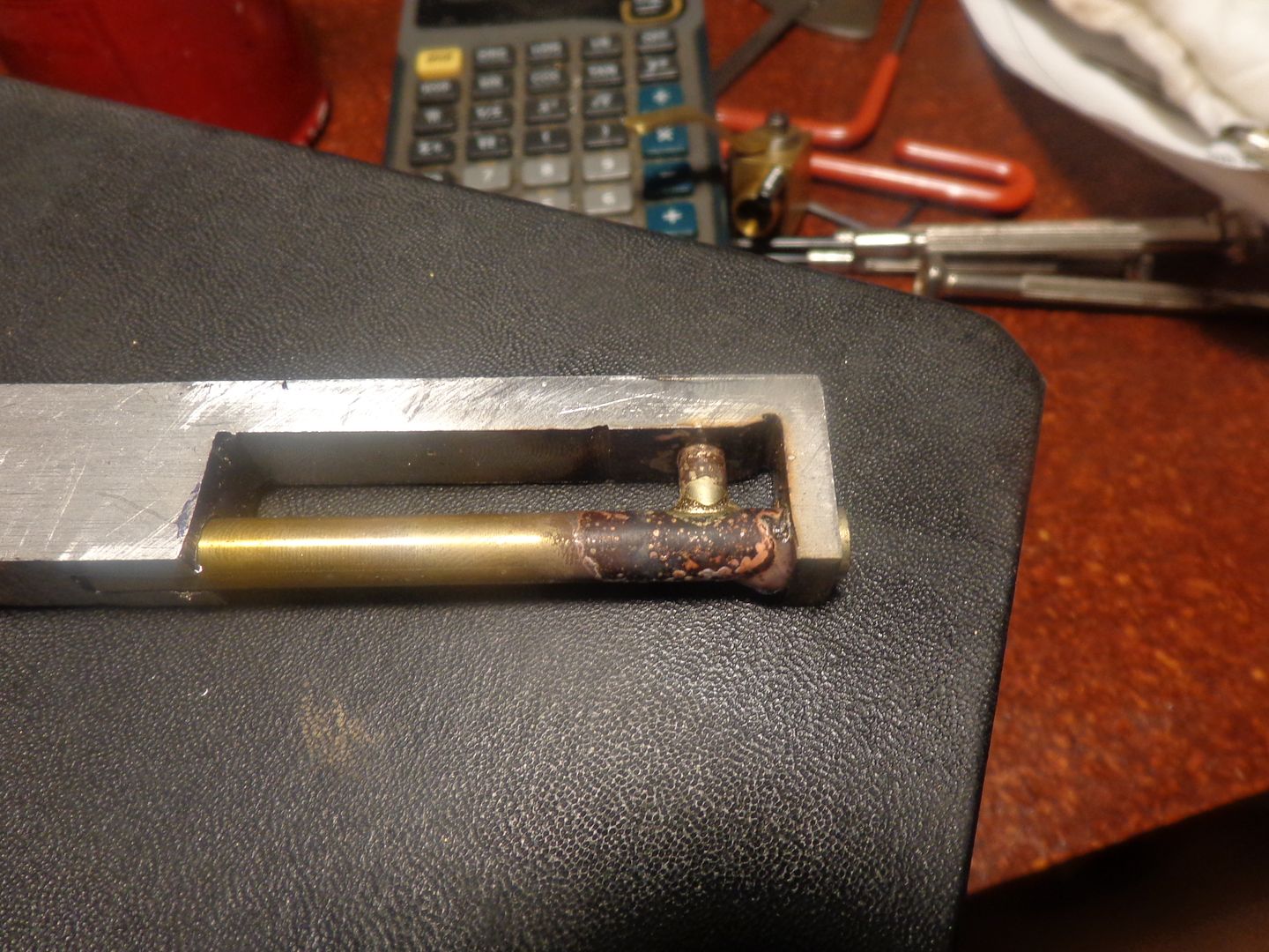
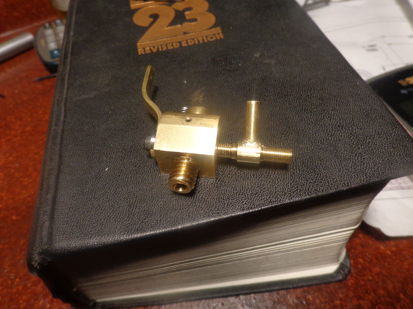
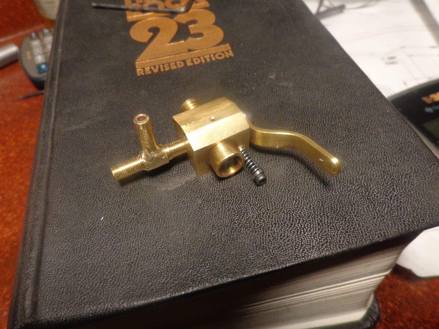
Progress has come to a stop. The new brass outer body is finished. In the process of making the new barrel, I convinced myself the safest way to ensure concentricity was to insert it firmly into the brass outer body and drill it in place. This worked fine for the 0.156" diameter thru hole. I then rejigged the part and went to spot thru the #2-56 threaded hole for the idle stop screw so I would be able to get the slot in the correct place. I opened the drawer with my 1/16" end mill in it, and guess what!!! The Shop Pixies have taken it away. I don't want to tear down my set up, so everything will set until tomorrow when I can get over to the tooling shop and buy a couple of new end mills. I can't spot thru with a drill, because it is not on the center of the 3/8" diameter steel, so a drill would slide sideways and tear up the threads in the brass part.
You are using an out of date browser. It may not display this or other websites correctly.
You should upgrade or use an alternative browser.
You should upgrade or use an alternative browser.
Model I.C. Carb with Throttle
- Thread starter Brian Rupnow
- Start date

Help Support Home Model Engine Machinist Forum:
This site may earn a commission from merchant affiliate
links, including eBay, Amazon, and others.
Thanks Necchiom---I find this very fascinating, even when I screw up and have to make everything a second time. Thankfully, that doesn't usually happen.----Brian
- Joined
- May 27, 2010
- Messages
- 2,999
- Reaction score
- 1,171
Plan to make this Carb for my Webster IC Engine. 
I have exhaust valve collision with piston when H&M cut-in. Just figured out a fix.
I have exhaust valve collision with piston when H&M cut-in. Just figured out a fix.
Today we are back to the point we were at when I figured out that my first design had a fatal flaw. The carb outer body is remade, and the steel center barrel is remade as well. What a pin in the butt!!! One pic shows the assembled carb setting up posing for an "overall" shot, one shows it with the throttle closed. (The closed position is adjustable) The throttle never closes completely, otherwise the engine would stop. It is only when the carb is closed to the position showed that the air bleed screw comes into play.--And remember, since the openings in both sides of the brass barrel are the same size on each side of the throttle barrel, the amount of opening on the side closest to the cylinder head will be open exactly the same amount as the opening on the air intake side. If the engine falters when the throttle is in this closed (idle) position shown, then the air bleed screw can be adjusted to smooth out the idle. Once the throttle is swung into a more open position, the idle circuit is blocked by the side of the barrel and has no effect on the carburetor.
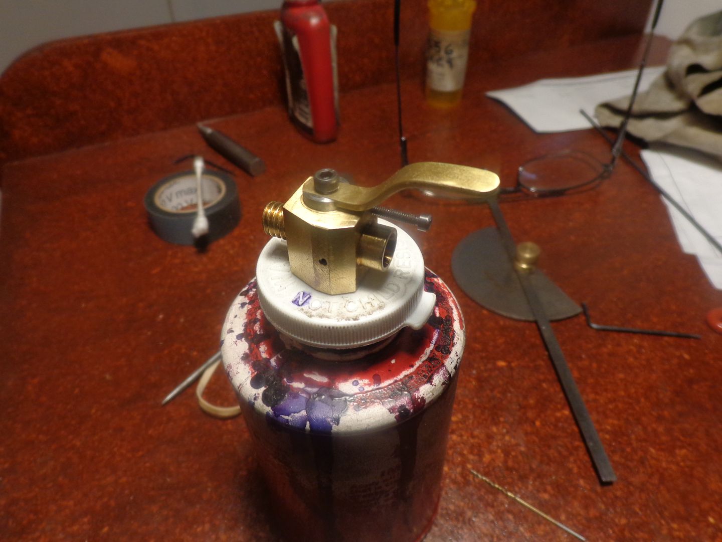
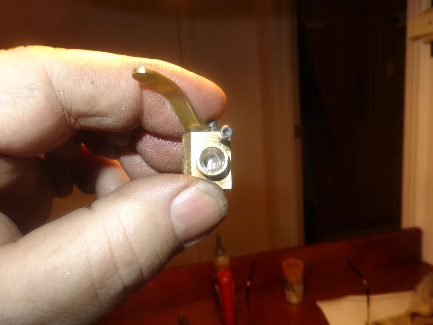


This is the best shot I could get of the carb with fully open throttle. What appears to be a bit of dirt right at the top of the barrel bore is actually a bit of metal displaced by the drill when I tapped the hole for the bolt holding the handle on. I will clean that up and plug it with a bit of thread sealant on the handle bolt.


$89.99
Outdoor Wood Boiler Water Treatment Rust Inhibitor- AmTech 300 & Test Kit
Alternative Heating & Supplies

$29.95
Competition Engine Building: Advanced Engine Design and Assembly Techniques (Pro Series)
Amazon.com Services LLC

$12.56
$39.95
Complete Plans for Building Horse Barns Big and Small(3rd Edition)
ThriftBooks-Atlanta
![DreamPlan Home Design and Landscaping Software Free for Windows [PC Download]](https://m.media-amazon.com/images/I/51kvZH2dVLL._SL500_.jpg)
$0.00
DreamPlan Home Design and Landscaping Software Free for Windows [PC Download]
Amazon.com Services LLC

$99.99
AHS Outdoor Wood Boiler Yearly Maintenance Kit with Water Treatment - ProTech 300 & Test Kit
Alternative Heating & Supplies

$24.99
$27.99
HOZLY 5PCS/Lot ISO30 Tool Holder Clamp Flame Proof Rubber Claw CNC Machines Automatic Tool Changer
HOZLY

$39.99
$49.99
Sunnytech Low Temperature Stirling Engine Motor Steam Heat Education Model Toy Kit For mechanical skills (LT001)
stirlingtechonline

$24.99
$34.99
Bowl Sander Tool Kit w/Dual Bearing Head & Hardwood Handle | 42PC Wood Sander Set | 2" Hook & Loop Sanding Disc Sandpaper Assortment | 1/4" Mandrel Bowl Sander for Woodturning | Wood Lathe Tools
Peachtree Woodworking Supply Inc

$519.19
$699.00
FoxAlien Masuter Pro CNC Router Machine, Upgraded 3-Axis Engraving All-Metal Milling Machine for Wood Acrylic MDF Nylon Carving Cutting
FoxAlien Official

$40.02
$49.99
Becker CAD 12 3D - professional CAD software for 2D + 3D design and modelling - for 3 PCs - 100% compatible with AutoCAD
momox Shop

$94.99
$109.99
AHS Woodmaster 4400 Maintenance Kit for Outdoor Wood Boiler Treatment
Alternative Heating & Supplies
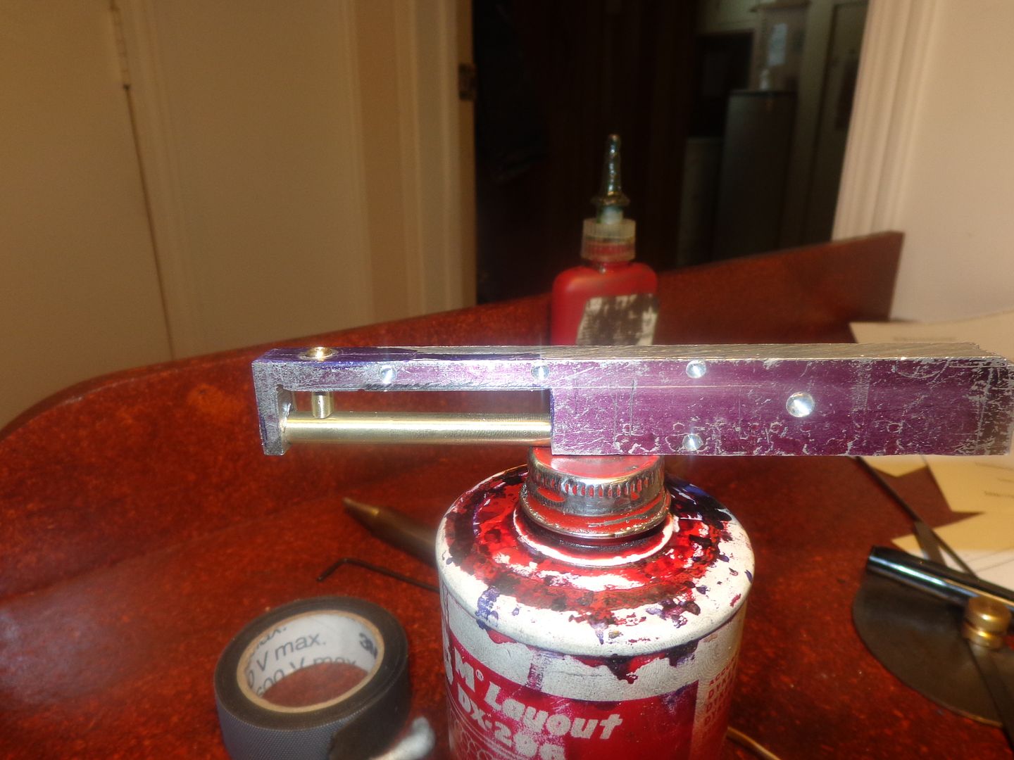
What you see here is a temporary disposable jig, made from aluminum. There is simply no other good way that I know of to position the two brass pieces correctly in relationship to each other, and then not have them move while silver soldering them. The jig is "temporary and disposable" because it has to be cut apart to get the soldered assembly out of the jig. The short piece of brass is for the fuel line to attach to, and has been turned to its finished size, and the hole drilled part way thru the center of it. The longer brass part is 1/4" diameter and will be turned down to finished size on each side of the fuel inlet before being threaded #10-40 on both ends. At some point while it is in the lathe chuck, the tapered end will be machined and the thru hole will be drilled. After that, the hole part way thru the short piece will be extended until it intersects with the central fuel passage.

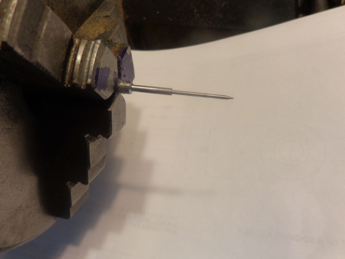
WOW!!! I didn't think I was going to be able to do this. That small diameter is 0.050". The smallest thing I had ever machined before was 0.093" dia. valve stems. I used a 3/16" cold rolled rod, and put the taper on the end while the rod was still at full 3/16" diameter. Then I started turning at 1000 rpm for 1/8" at a time right down to 0.050, then move ahead and machine the next 1/8" down to 0.050. I followed the same procedure to turn the 0.100" diameter. I tried to keep all machining as close to the chuck jaws as possible. I'm not even going to try to part it off. I will use the hacksaw while it is still locked in the chuck to cut it off, then use my belt sander to cut it to length.--To keep from feeding the swarf bunnies, I will wrap a length of masking tape around the part before I cut it off.

Philjoe5
Well-Known Member
- Joined
- Jul 12, 2007
- Messages
- 1,727
- Reaction score
- 321
There we go---All finished. I cheated on the locknut---took a #10 std. pitch nut and rethreaded it. The soldering of the needle valve went very well, with no miss-haps. I have much better luck with silver solder than I do with plumbers soft solder. I coated the knurling on the needle valve with white out to keep any overflows of silver solder from sticking in the knurling. It works a treat, but I had a devil of a time getting the white-out off after the fact. I tried hot paint thinners, varsol, dishsoap, Goo-Gone, and toothpaste and hot water, all scrubbed with an old tooth brush, and I think there is still some on there. The drawings all have to be updated and changed to reflect what actually got built, but I will do that later today. Damn, it's a lot of work when you have to make the two main parts twice!!!--The $64,000 question will be now---Does it work!! As soon as the weather gets nice enough that I can work out in my main garage without freezing to death, I will be testing this carb and Chuck Fellows' carb on my old tried and true Webster, and will try and give an unbiased report and a video of the results.---Brian

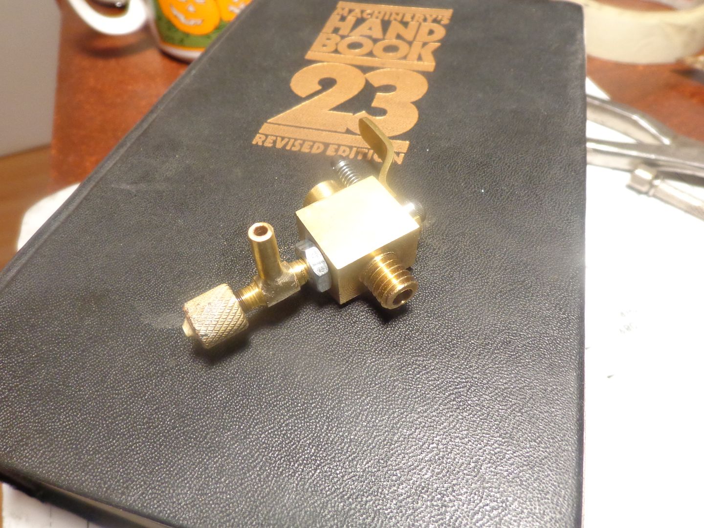
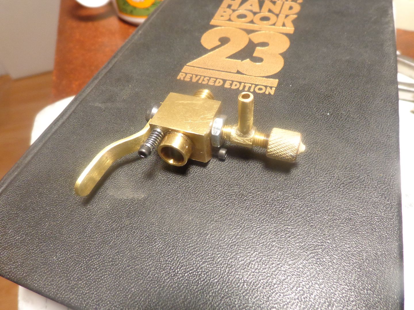


As of this evening, 18-March-2014, I have replaced all of the drawings in this build thread with the most current drawings. They are all up to date now.---Brian
- Joined
- Jul 16, 2007
- Messages
- 3,061
- Reaction score
- 1,203
Hi Brian,
Congrats on the carb build. It looks great! I see no reason why it shouldn't work. Start with the air bleed open half way. With the needle barely open start turning the engine over. Choke once with finger, if it doesn't pop open the needle a touch more and repeat.
gbritnell
Congrats on the carb build. It looks great! I see no reason why it shouldn't work. Start with the air bleed open half way. With the needle barely open start turning the engine over. Choke once with finger, if it doesn't pop open the needle a touch more and repeat.
gbritnell
Thank you very much George. I take that as a great compliment. All I need now is some warm weather to get out in the main garage and test it.--Brian
- Joined
- May 27, 2010
- Messages
- 2,999
- Reaction score
- 1,171
Thank you very much George. I take that as a great compliment. All I need now is some warm weather to get out in the main garage and test it.--Brian
Hi Brian,
When winter comes,spring is not faraway.( Weekend just three days away to hook up some slimy big fish.)
Making some progress on the H&M device.Just take my sweet time putt-putting your engine. Could spent the whole morning enjoying the putt-putts.
Take care.
This is the Webster engine I will be trying the two different carburetors on. As you can see, it already has an adapter on it to hold the Traxxas Pro 15 model airplane carb on it. (the Traxxas has a 10mm plain outer barrel diameter.)
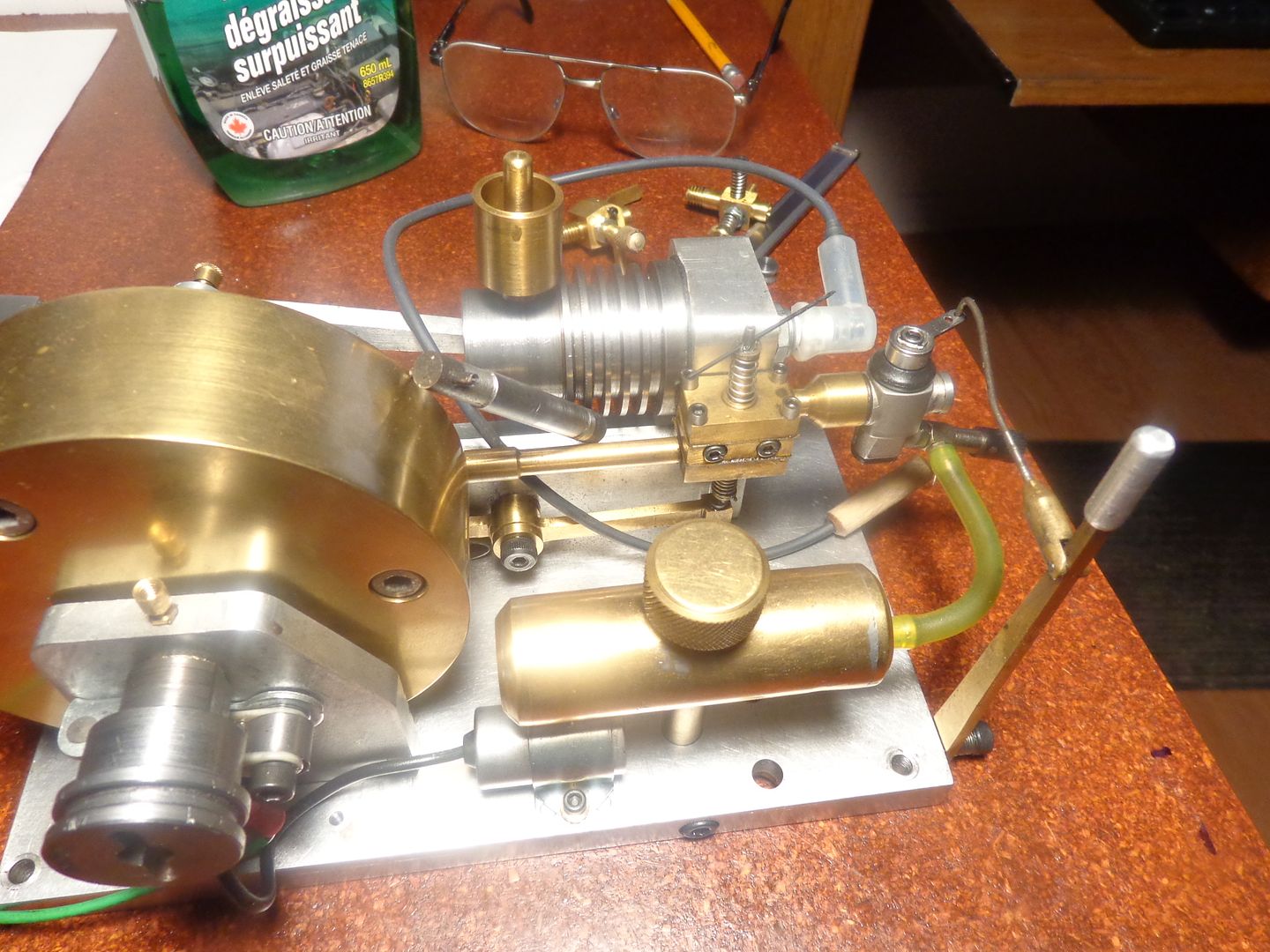
This is the adapter I will make today so the two different carbs can be tested. The small diameter of the adapter must be Loctited into the Webster intake manifold.


This is the adapter I will make today so the two different carbs can be tested. The small diameter of the adapter must be Loctited into the Webster intake manifold.

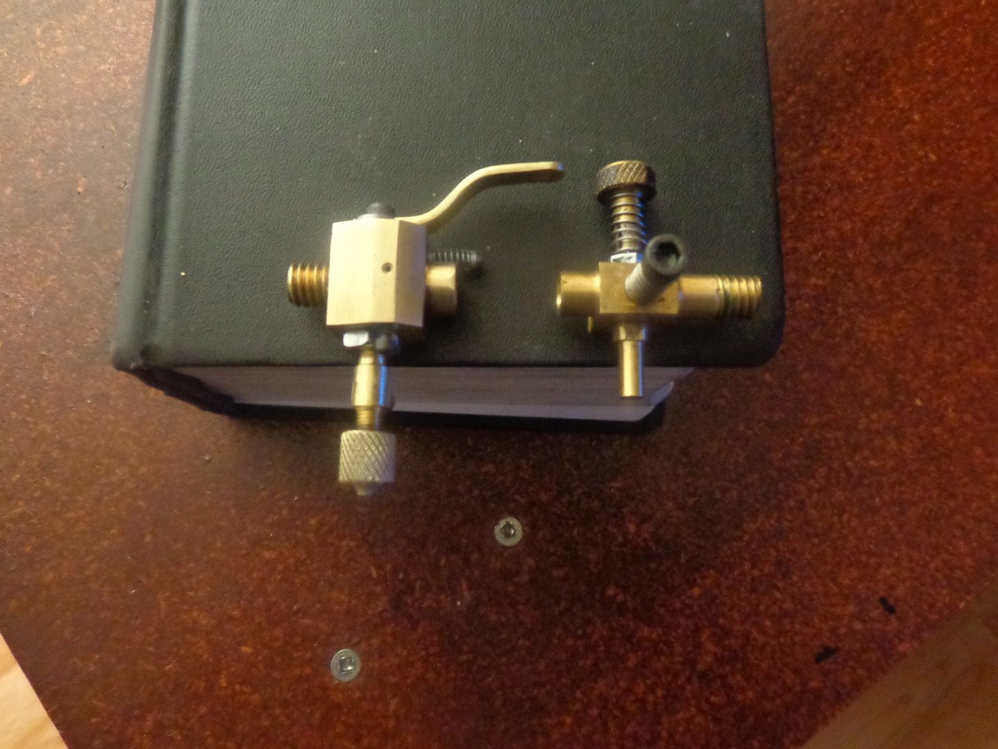
A very minor change in direction this morning- I realized that with the air bleed adjustment screw on the bottom of the carb as originally planned, it would be difficult to get at and adjust while the engine was running. So--I drilled and tapped the #2-56 hole completely through to the top of the carb body and plugged the bottom of it with a short #2-56 shcs. Then I made a very small notch for clearance in the handle, machined up a knurled adjustment knob, and threaded it, then Loctited it to a #2-56 screw x 3/4" long. Now I can adjust it from the top side where it is easy to reach. Also in these pics you can see the adjuster which will let me attach this carb or Chuck Fellows' carb to my Webster engine.


Similar threads
- Replies
- 11
- Views
- 918
- Replies
- 28
- Views
- 7K
- Replies
- 413
- Views
- 65K


![MeshMagic 3D Free 3D Modeling Software [Download]](https://m.media-amazon.com/images/I/B1U+p8ewjGS._SL500_.png)


