Finally back to making an actual engine.
The ME Beam is a very pretty engine when finished, with quite a lot going on. As a basis I am using the Reeves offering of castings, which I purchased about 2 years ago I think. My initial look over the castings says they are OK - not warped or twisted or anything so I'm looking forward to an enjoyable, completely trouble free and relaxing experience.
Don't worry, I can usually steer myself down paths that bring their own trouble and woes.
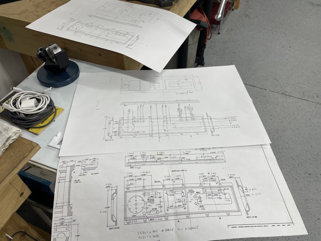
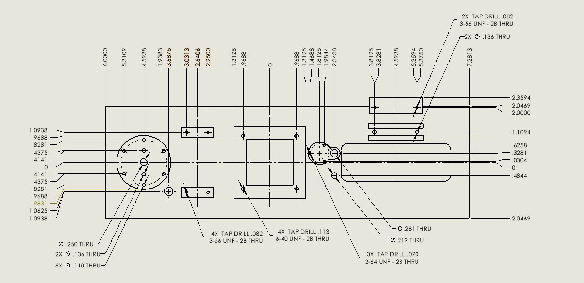
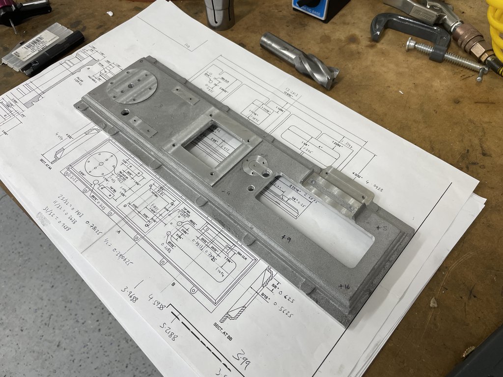
So all I've done so far is spend some time with the base plate. As seems normal on casting kits, the way the parts are dimensioned is largely inappropriate, and if not interpreted correctly could steer the unwary quite wrong I think.
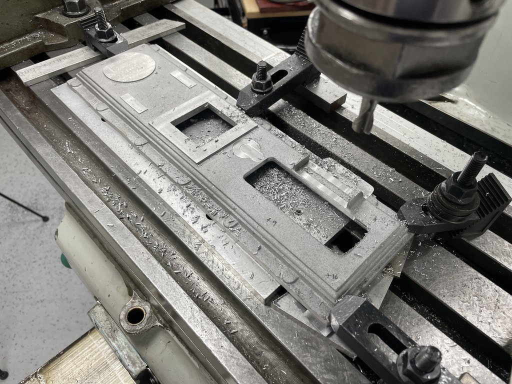
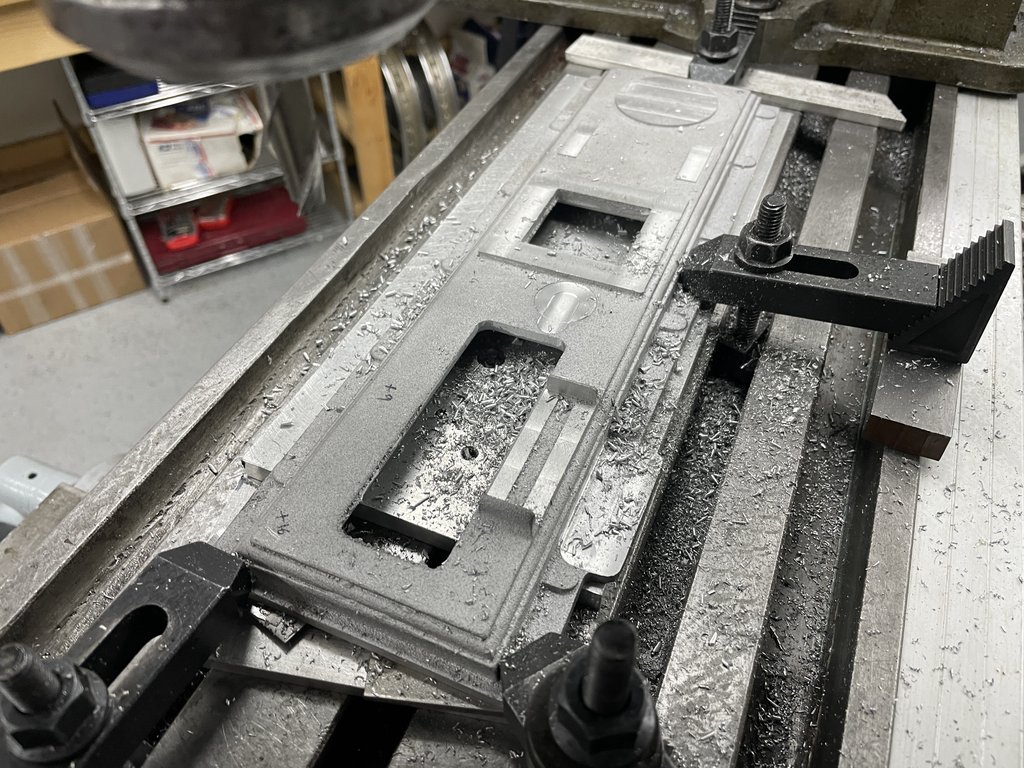
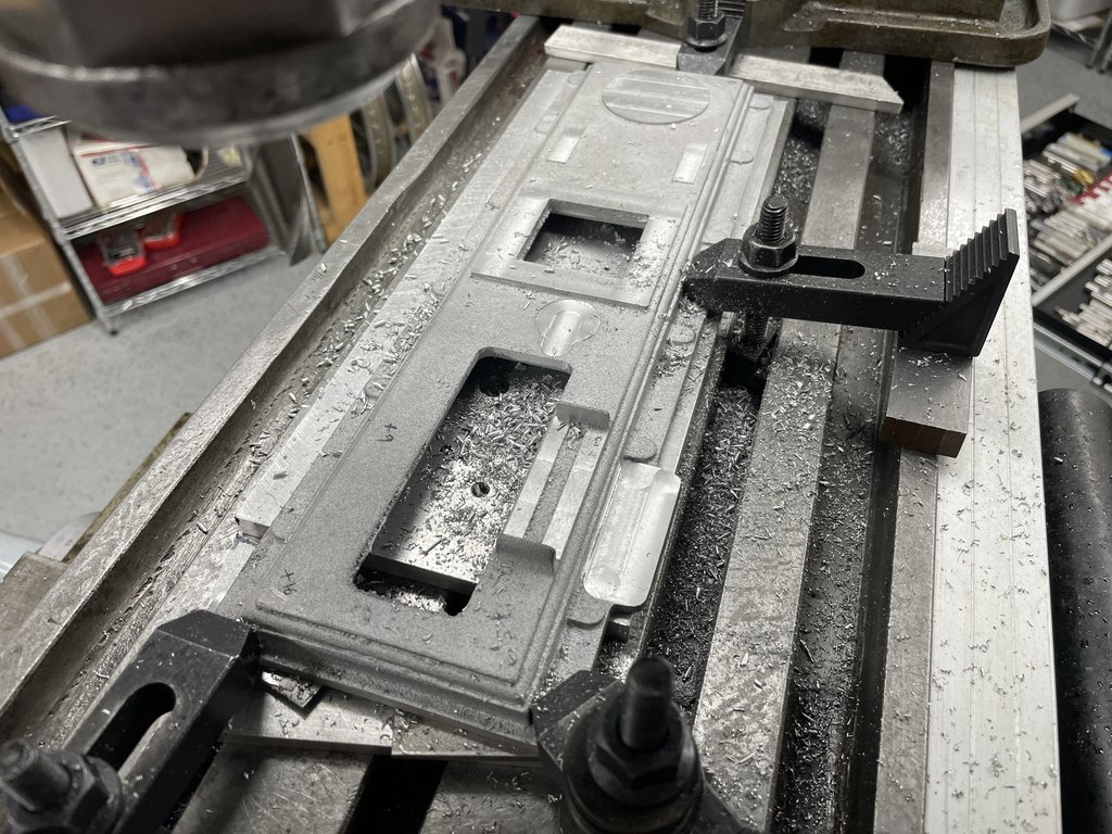
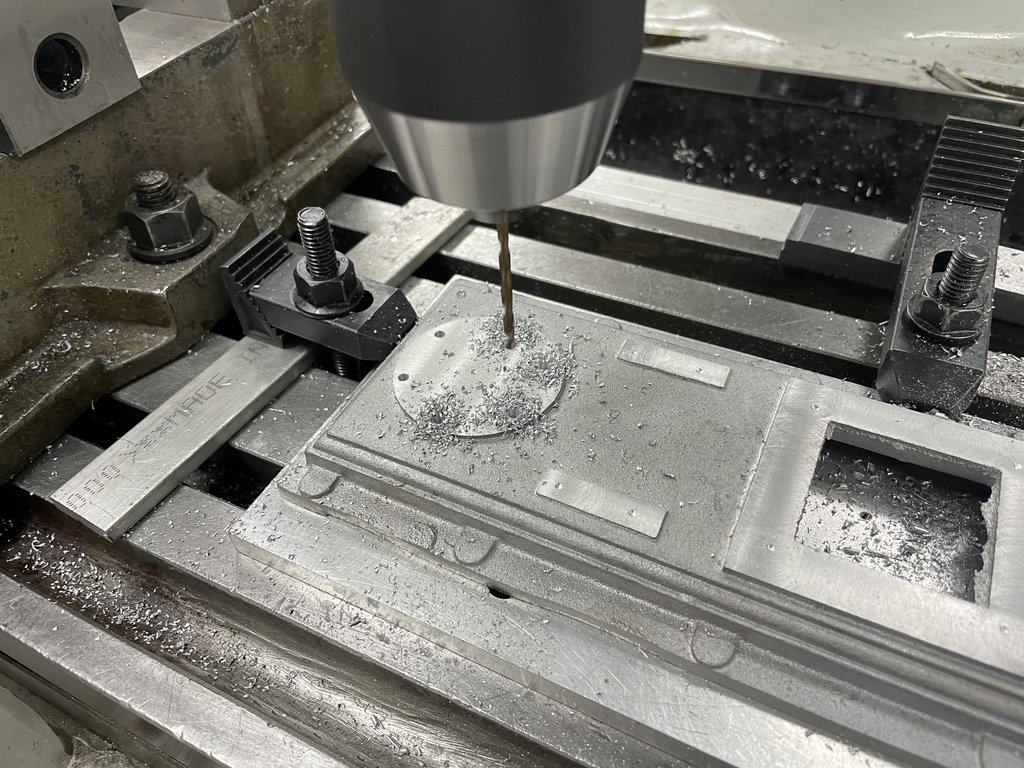
For now all I've done is best condition the casting and skim the underside flat. Hey - it's a start. this done in such a way as to maintain enough machining stock on the top side features to get everything where it needs to be.
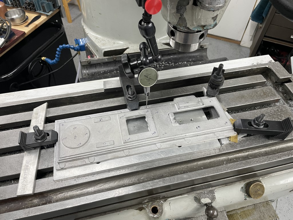
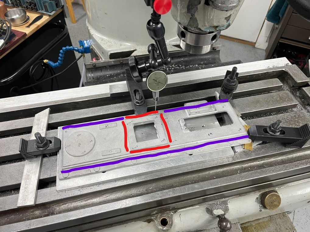
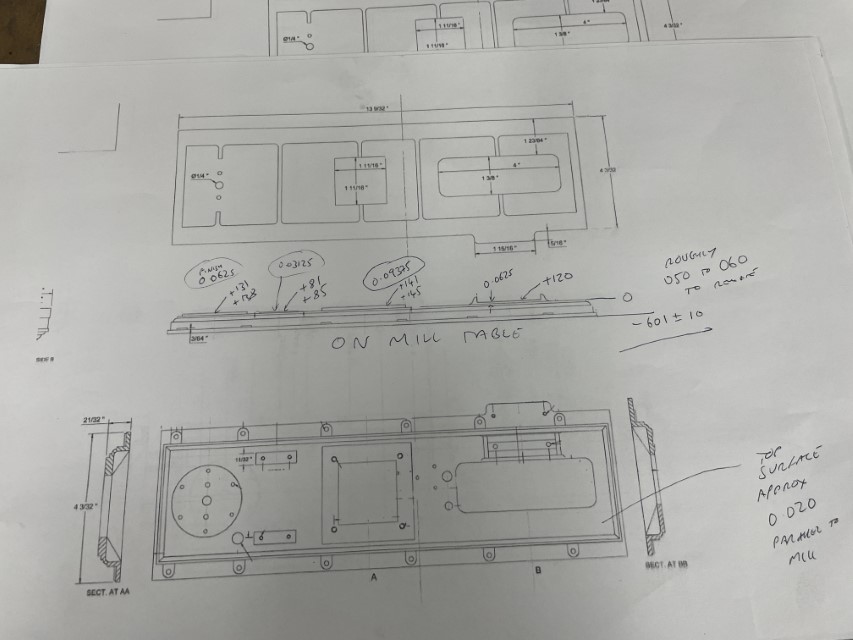
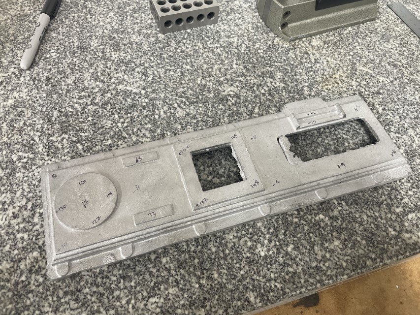
Best conditioning is the term we used at my last job to essentially balance the set up of a weldment or casting for the best combination of maximum machining stock on all features that get machined, while at the same time not distorting the part with clamping, and then also maintaining visual appeal as needed. What it means in this case is that I measured the casting all over as well as probing it with a height gauge on my surface plate to figure out how twisted / distorted it was. In reality actually pretty decent - about 25 thou variation across the main surface that is to be unfinished, same on the underside, with about 1/16" of stock on most surfaces, so pretty easy to level up and get going on.
The numbers on the casting represent height differences in thousandths of an inch from one corner.
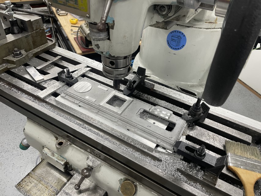
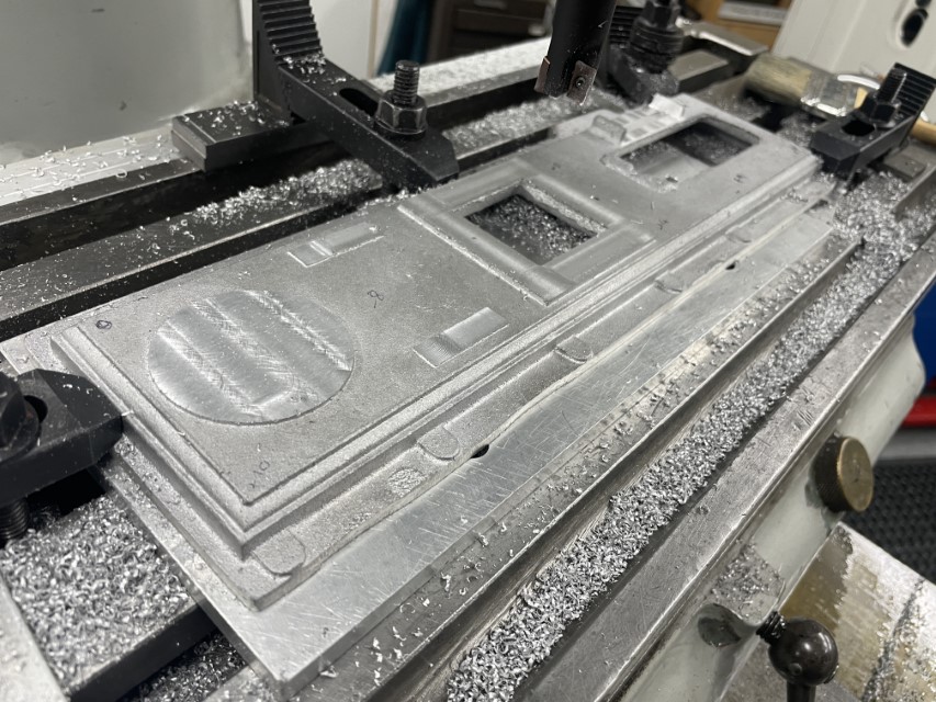
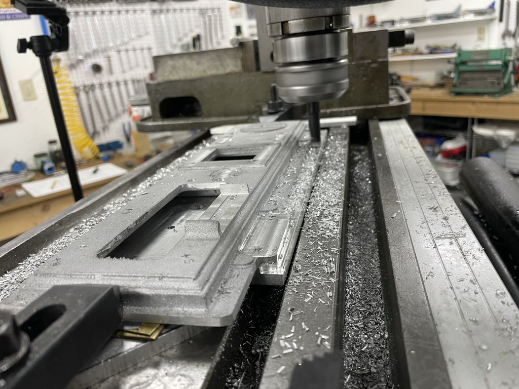
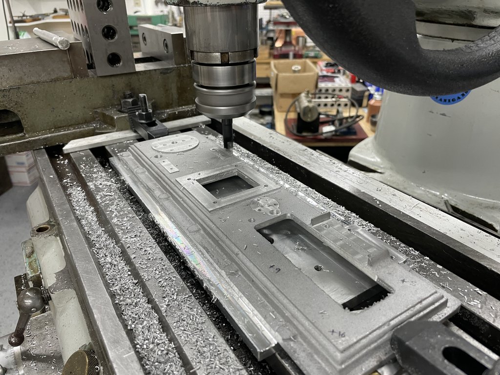
Then up on the mill and skimmed the underside a few thou at a time until it cleaned up. I'd established that the center square feature where the column goes is actually the least out of flat, and indeed that resulted in only skimming about .020" off the highest point to get full clean up. I supported the part on a couple of machinist jacks as well to stop it flexing during cutting. It was a bit of a lightly clamped set up so I just took it really easy. After checking the finished cut on the surface plate there is no rock, so now I can get it clamped really well, best condition it on the table and start on real features.
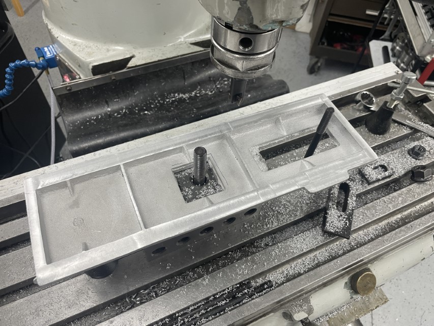
Not much of a start - on the other hand quite the setting of the foundation.
I see I need to get back into the swing of taking pictures as I go. Blasted YouTube channel has me focusing more on that than still pics. In due course there will be video offerings as well but man they take some work editing.
The ME Beam is a very pretty engine when finished, with quite a lot going on. As a basis I am using the Reeves offering of castings, which I purchased about 2 years ago I think. My initial look over the castings says they are OK - not warped or twisted or anything so I'm looking forward to an enjoyable, completely trouble free and relaxing experience.
Don't worry, I can usually steer myself down paths that bring their own trouble and woes.
So all I've done so far is spend some time with the base plate. As seems normal on casting kits, the way the parts are dimensioned is largely inappropriate, and if not interpreted correctly could steer the unwary quite wrong I think.
For now all I've done is best condition the casting and skim the underside flat. Hey - it's a start. this done in such a way as to maintain enough machining stock on the top side features to get everything where it needs to be.
Best conditioning is the term we used at my last job to essentially balance the set up of a weldment or casting for the best combination of maximum machining stock on all features that get machined, while at the same time not distorting the part with clamping, and then also maintaining visual appeal as needed. What it means in this case is that I measured the casting all over as well as probing it with a height gauge on my surface plate to figure out how twisted / distorted it was. In reality actually pretty decent - about 25 thou variation across the main surface that is to be unfinished, same on the underside, with about 1/16" of stock on most surfaces, so pretty easy to level up and get going on.
The numbers on the casting represent height differences in thousandths of an inch from one corner.

Then up on the mill and skimmed the underside a few thou at a time until it cleaned up. I'd established that the center square feature where the column goes is actually the least out of flat, and indeed that resulted in only skimming about .020" off the highest point to get full clean up. I supported the part on a couple of machinist jacks as well to stop it flexing during cutting. It was a bit of a lightly clamped set up so I just took it really easy. After checking the finished cut on the surface plate there is no rock, so now I can get it clamped really well, best condition it on the table and start on real features.

Not much of a start - on the other hand quite the setting of the foundation.
I see I need to get back into the swing of taking pictures as I go. Blasted YouTube channel has me focusing more on that than still pics. In due course there will be video offerings as well but man they take some work editing.


