mini-lathe - getting it right...maybe

Home Model Engine Machinist Forum

Help Support Home Model Engine Machinist Forum:

This site may earn a commission from merchant affiliate links, including eBay, Amazon, and others.
Im watching and coming along for the ride... all it took was a promise of "but a good heart" ..... Im a sucker for a good story....

Im using a much much larger older lathe.... accuracy is something I dont take for granted but are yet to have a problem with (I think). Im hoping to learn how to ensure that I dont in future.....

Keep the info flow happening.... ;)
 
Thanks Bogs. And I got a favor to ask. If I remember right, you provided a link to me that showed a modification for the carriage gibs on the mini-lathe. Angled brass that slid against each other. I've looked and looked for that link but haven't found it. If it's at the tip of your finger I'd appreciate the link again. Not that I will necessarily do this, but I want to consider it.

Thanks Tim. I have no collets for the lathe. Thanks for reminding me of that. I need to go looking.

Thanks Rick. I thought about that too. I intend to do several different and same measurements to (as Bogs mentioned) get to know my equipment.

Thanks Artie. I hope you find it useful. It's going to be slow going I'm afraid.
 
Well I did another measurement...this time with the DTI set to the inside of the ram. It only measures up to .0013 and I pegged it either direction. I don't know what's different but I wasn't happy.

[EDIT: To Bogs' point...I need to check out and/or true the chuck before I can really do anything with the tailstock. But no problem getting an idea of things as I go along.]

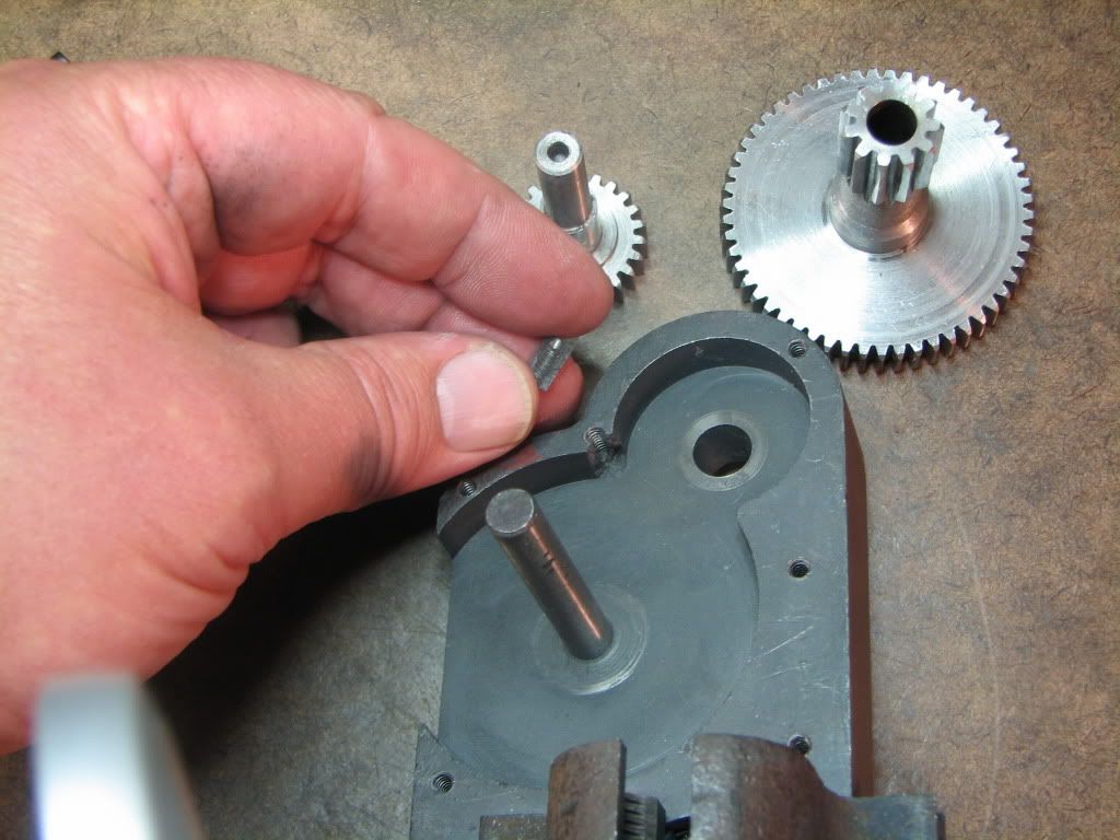
I put the apron back together. Some of you may recall the 'boo-boo' I had last year when I was drilling the holes for the plastic shield. The bit that cracked came off. No harm though...the shield and apron will work fine.

I did discover that I'd attached the wheel incorrectly last time. So the small gear was sticking out further...and that's the reason for the grease on the plastic.

26012e01.jpg


One measurement in the evening doesn't sound like a lot (and it's not) but it's grab a minute here...grab a minute there...ah...got air that time.

Exciting isn't it?
Well of course it is.
Not worried if you're not excited. I'm the one that counts. :big:
 
While I'm here and got another minute...

Now's a good time to consider additional modifications...

One of the mods I came across was to split the nut that sits under the cross slide. At the time I had no experience with a saw blade on the mill (remember the time I had it cutting backwards?). Now I feel more confident. Anyone else have experience with cutting the nut?

I also want consider attaching a caliper or two. (No electronics for me...I'm really burned out doing 'work related' stuff.).

Any suggestions for other improvements?

I know about a power feed for the carriage...but I don't think I need it. I enjoy the manual work.

I may return to fixing the clamp for the tailstock...but I think it just needs a shim.

A spindle stop would be good. And tools...I'd really like to make some die holders like Arnold did.

I'll tell you...getting the lathe cleaned up is really putting pressure on me to just put it together and get back to machining...

I think I'll join Jerry and get a refill.
 
Hey all...I haven't posted since yesterday and I'm still at #2 in this topic. C'mon...get busy and make some more machine mods! ;D

I've been interested in that mod of Bogs (the gibs) for some time...but I think it's still going to be some time before I get to it. It looks like it requires a bit more 'skill' than I have right now. If you don't want to buy that excuse...then please accept the fact that my mill needs a lot of work to make such good pieces.

In any case...before I make such major mods...I need to understand my lathe better. So I'm going to clean it up, put it together, and see how much better I can make it as is.

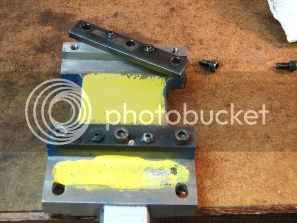
I worked on the carriage a bit today. Here's a pic of it upside down. A couple of things I noticed...

The gibs (well not gibs, the thingies that ride along the bottom) were loose. Real loose. Maybe they were tighter while mounted on the lathe...but I'm thinking I didn't have them adjusted very well.

On a brighter note...I've seen web sites that talk about those thingies and how they can break pretty easily. But the pictures I've seen of them showed them much thinner than the ones I have. It looks like the manufacturer increased their size to minimize the breakage. Well we'll see.

b840fbb0.jpg


I used my compressor to help clean out the swarf and kerosene. I forgot to cover the lathe, the wall, and myself. Spotted all over now.

 
Zee, maybe something else to consider with the tailstock...

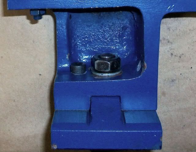
I replaced that useless capscrew on the bottom of the tailstock with a capscrew on the top where you can actually get to it when trying to do an alignment.

TailstockCapscrewTop.jpg

When you do that, tailstock alignment is a lot easier. Example of that mod <a href="http://www.homemodelenginemachinist.com/index.php?topic=8834.msg95996#msg95996">HERE.</a> I also added compressor man's adjusting system, helped even more, shown by him <a href="http://www.homemodelenginemachinist.com/index.php?topic=8834.msg98270#msg98270">HERE.</a>

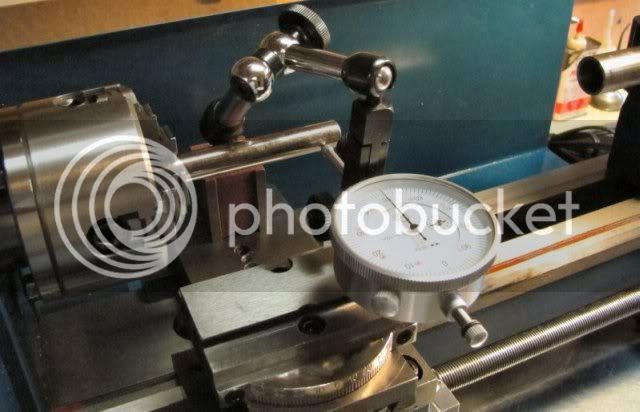
With those mods, this is the way I now align my tailstock. First I find the centerline of the lathe by putting a test bar in the 4-jaw and centering it. My test bar is 0.500" in diameter, therefore I know the centerline of the lathe has to be 0.250" in from its outer surface. So I adjust the cross slide to force a reading of 0.250" on the dial indicator, giving me an indicator and cross slide set so that 0.000 on the indicator is at the centerline of the lathe. (I temporarily remove the tool holder and compound from the cross slide to make it easier to locate the indicator and its magnetic base.)

FindingZero.jpg

I lock the tailstock and crank out the tailstock quill until it's almost fully extended, and lock it there. Then, without changing anything about the dial indicator, I carefully move the carriage down the ways toward the tailstock while pulling out on the top end of the indicator stem so the stem will clear the end of the quill, and stop the carriage so the indicator is now measuring the quill. My tailstock quill is 0.866" in diameter, so if the center of the tailstock quill is actually aligned with the lathe centerline, the outside of the quill should now indicate 0.433" along its entire length. If it doesn't, I adjust it until I'm satisfied with it.

CheckingQuill.jpg

Screwing in one of those added adjustment screws swivels the whole tailstock around and changes what was done with the other screw, so the alignment process is an iterative process (at least it is for me). I found that the best way to make progress is to work toward minimizing the difference in readings from one end of the quill to the other first, without regard to the actual distance from the centerline. Then, when I'm satisfied that the quill is parallel with the centerline, I tweak both adjustment screws in or out in unison to get the quill axis aligned with the center of the lathe. I leave my test bar in the chuck during the alignment. If the dial indicator gets bumped accidentally during the process and my reference measurement is lost, I just crank the carriage back to the test bar, set it again, and continue.

Aligning the tailstock this way assumes a lot, including that of the headstock being reasonably aligned with the centerline of the lathe. From what I've read, a good way to check headstock alignment on our hobby lathes is <a href="http://neme-s.org/Rollie's_Dad's_Method.pdf">Rollie's Dad's Method</a>. When I checked mine, it was off about a thou and a half over five inches, IIRC.

Regards,
Rudy
 
Thanks for the link Chuck! I remember following that thread. A wealth of good information.

Why did you build a tool post for cutting tapers rather than using the compound? More rigid?

Thanks Rudy. Very helpful! I popped a bar out of a printer so that should be helpful.
 
zeeprogrammer said:
Thanks for the link Chuck! I remember following that thread. A wealth of good information.

Why did you build a tool post for cutting tapers rather than using the compound? More rigid?

There were a number of reasons to replace the compound with one that fits on my "quick change toolpost". First, the supplied compound takes up a lot of real estate on the cross slide and I rarely use it. Second, I don't like having to crank the compound all the way out to loosen the screws so I can change the angle or remove it. And, third, my QC toolpost mounted on the cross slide is more rigid than than if it were mounted on the compound. I prefer to treat the compound as just another accessory for my QC toolpost rather than a main component of the lathe.

Chuck
 
zeeprogrammer said:
Bogs...thanks for the link. I have no means at hand for modifying the chuck but shimming the headstock is something I'll have to look into. Right now the carriage and so on are broken down for cleaning.

Zee; I think your spindle has an MT3 taper doesn't it? If you want to check / square up the back of the chuck I have a 1/2" MT3 collet that you can borrow for this. Just let me know. Might also come in handy for setting up the head. Eliminates the chuck entirely.
 
Thanks Chuck. All good points. I'll have to think about how much I use the compound. That has so far been a source of many issues I've had.

Thanks Rick. Let me get further down the road...I may take you up on that.

-------------------------------

An update! An update!
Well not much of one.

I've been traveling, had visitors, and now that my garage is getting fixed up...all that stuff is in the basement.

But I did manage to put the carriage et.al. back together. It seems even better than before. I'm thinking it's because I've gotten to know the lathe more and gotten better at understanding torque requirements and play. In particular how to adjust the gibs. I highly recommend that people new to lathes take the time to take it apart and put it back together after a project or two. It makes a difference. At least for me.

Next step, when I can, is to see how the tail-stock lines up.

I have to admit I'm more anxious to build something rather than futzing with the equipment.

 
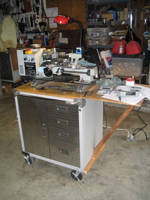
I'd like to raise my lathe up using some aluminum blocks.

2x3x4 solid is on the order of $10
2x3x4 rectangular is on the order of $2.50
I'd need two.

The rectangular has 1/8" wall thickness. Would that be strong enough?

It may be time to strike up a relationship with some scrap yard or machine shop around here.
 
Zee...

Sorry for being a bit late to your party. Been out of town with now web access for the last 6 weeks. However late I'd like to offer a copuple my experiences with the 7x10 lathe I had.

1. Slitting the brass nut on the compound was a snap and worked well. The only caveat is you need to go back and squeeze it closed now and then. I used a very thin hobby saw to make the slit. IIRC it's something like 10 thou thick. Do be careful to not make too thick a cut and break the nut when you squeeze it. (Ask me how I know that one! ;-))

2. Lap your compound and cross slide. Loads of arm work but well worth the effort. Make sure your gibs are straight.

3. If you have the time and inclination remove the silly set screw wetup on your carriage retainer plates and shim it to fit. I used strips of beverage can cut with scissors and perforated with a punch to make the shims. One of the best things I ever did.

4. Make sure the carriage rides flat on the ways. My carriage had a hump in the casting that would not allow the thing to sit flat on the ways. File the carriage, check again. File, che... layout juice is your friend. I finally got my carriage to less than .001" of movement up and down by the use of the shims and making sure the carriage was flat.

Item last. The removal of the compound as done by Chuck and others will go a long way toward improving rigidity. Flex is the #1 downfall of these machine IMHO.
 
zeeprogrammer said:
I'd like to raise my lathe up using some aluminum blocks.

Solid is overkill. I think 1/8" wall would be too thin. Here's how I did mine and I think it's 1/4" wall. Finding a local scrappy that lets you hunt around for stuff is a big bonus.

IMG_2391.jpg
 
Twmaster said:
Zee...

Sorry for being a bit late to your party. Been out of town with now web access for the last 6 weeks. However late I'd like to offer a copuple my experiences with the 7x10 lathe I had.

1. Slitting the brass nut on the compound was a snap and worked well. The only caveat is you need to go back and squeeze it closed now and then. I used a very thin hobby saw to make the slit. IIRC it's something like 10 thou thick. Do be careful to not make too thick a cut and break the nut when you squeeze it. (Ask me how I know that one! ;-))

....stuff deleted

What's the deal with slitting the brass nut on the compound? Is that to reduce backlash?

Chuck

 
What's the deal with slitting the brass nut on the compound? Is that to reduce backlash?

Chuck, yes, backlash reduction.
 
Twmaster said:
1.I used a very thin hobby saw to make the slit. IIRC it's something like 10 thou thick.

3. If you have the time and inclination remove the silly set screw wetup on your carriage retainer plates and shim it to fit. I used strips of beverage can cut with scissors and perforated with a punch to make the shims. One of the best things I ever did.

Thanks Mike (Twmaster). 10 thou eh? That's smaller than my 1/32 I have. I'll have to look around.

I don't understand #3. wetup? Where is the set screw? Thanks.

Thanks Mike (winklmj). I'm wanting to put the blocks between the lathe and the tray so I can get under and clean easier. On my way home I was wondering why not wood? The thing sits on wood anyway. Although...it would soak up oils and stuff...probably not a good idea. Under the tray would work...but that's not what I want.

Chuck...yeah...what Mike (Twmaster) said. Backlash. Although I'm wondering how the little setscrew that pushes down in the middle of it would work. I can't remember where I saw that mod. I think on mini-lathe.com or some link in it.

Thanks guys.

 
Come on Zee... get with the new lingo! ;)

What I was trying, and failing to say, is to remove the silly set screw setup from the carriage retainer gibs. Put shims in there. It took a bit of time to get right but worked great
 

Latest posts

Back
Top