Making a valve for model i.C. engines

Home Model Engine Machinist Forum

Help Support Home Model Engine Machinist Forum:

This site may earn a commission from merchant affiliate links, including eBay, Amazon, and others.

Brian Rupnow

Design Engineer
Project of the Month Winner
Joined
May 23, 2008
Messages
15,249
Reaction score
8,525
Location
Barrie, Ontario, Canada
Today we are in tutorial mode. This is going to be a tutorial on how I make intake and exhaust valves for internal combustion engines in the 3/4" to 1" bore range. This is not the only way, but this is the way I have had great success with over the last 12 i.c. engines I have built and ran. This style of valve works equally well for both cam operated valves and for atmospheric valves. In the attached drawing, we have a very typical valve, similar to what I use. There may be minor differences in the stem length, but otherwise this valve is identical to what I use. Keep in mind--my engines are not hi-revving, hi-performance engines. they run in the 700 to 3000 rpm range.
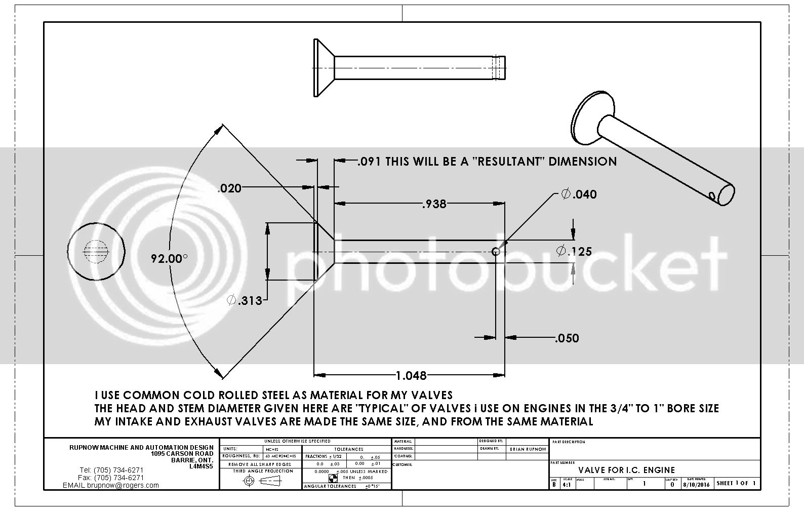
 
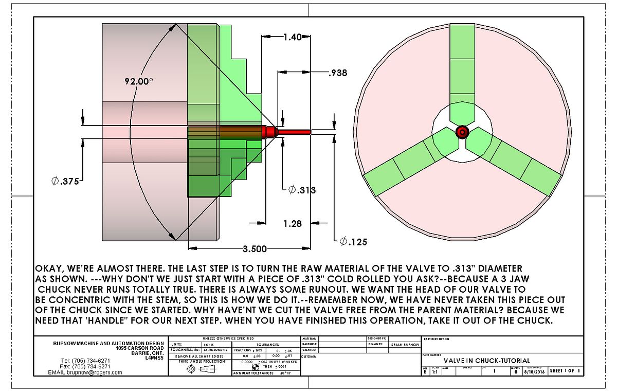
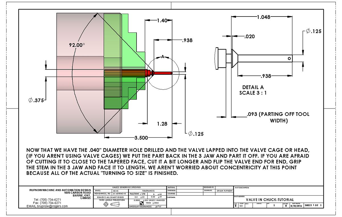
The valve in the drawing above is just slightly over 1" long. However, we are going to start this rodeo with a piece of raw material 3 1/2" long. The explanation why we use such a long piece of raw material will be explained as we move along.
 
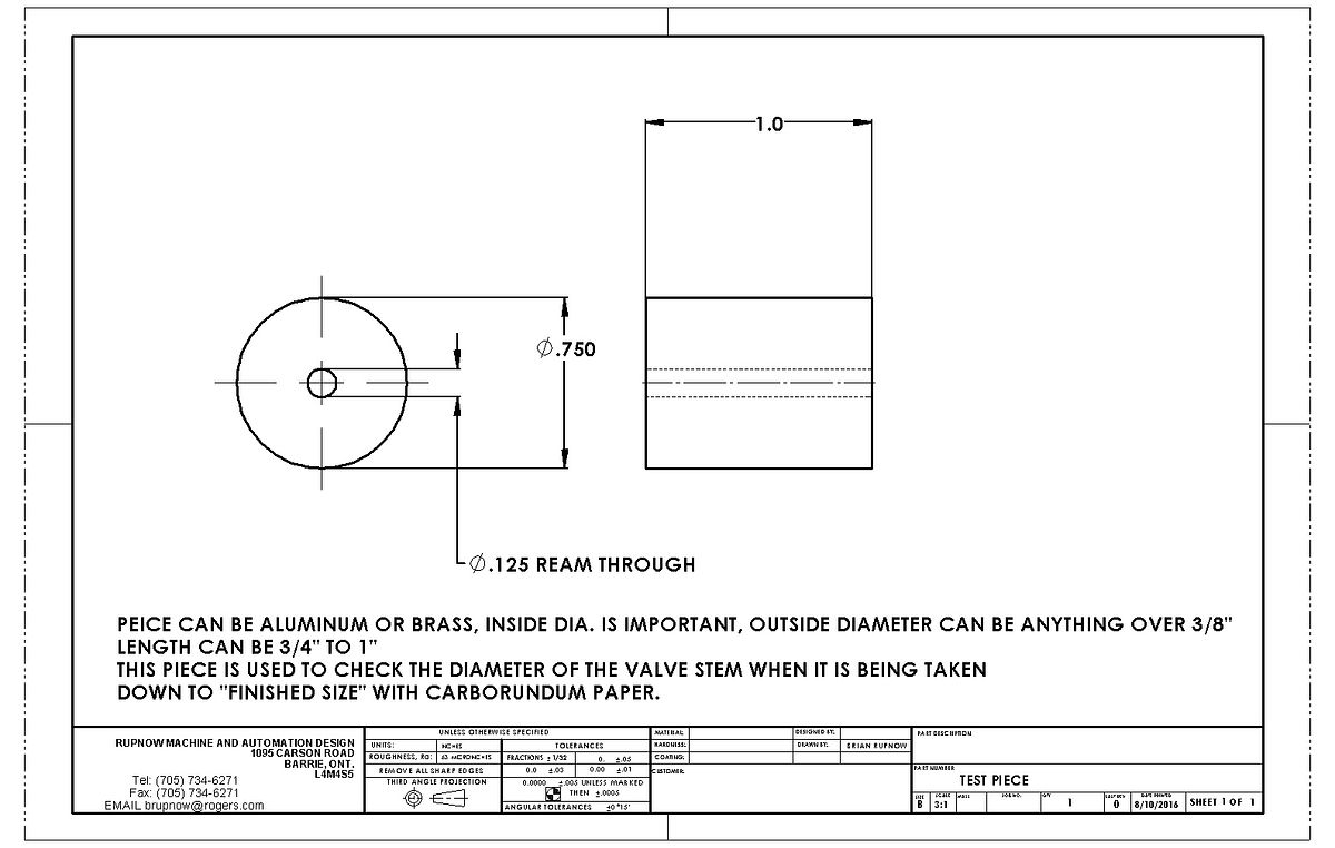
Before we go any farther, while the 3 jaw chuck on the lathe is still free, we are going to make one of these. Make it now, because we don't want to have to tear down the actual valve set-up in the lathe before we get the valve finished.
 
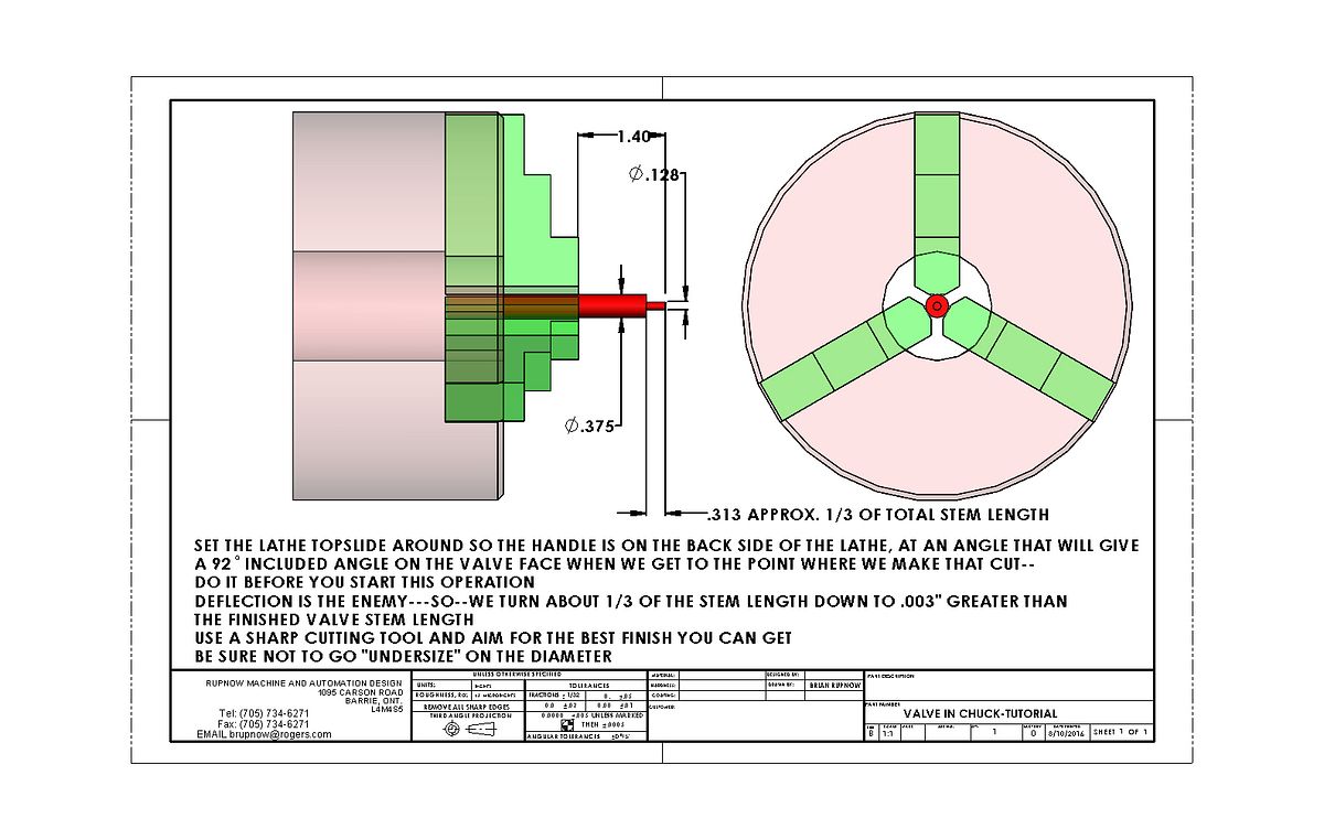
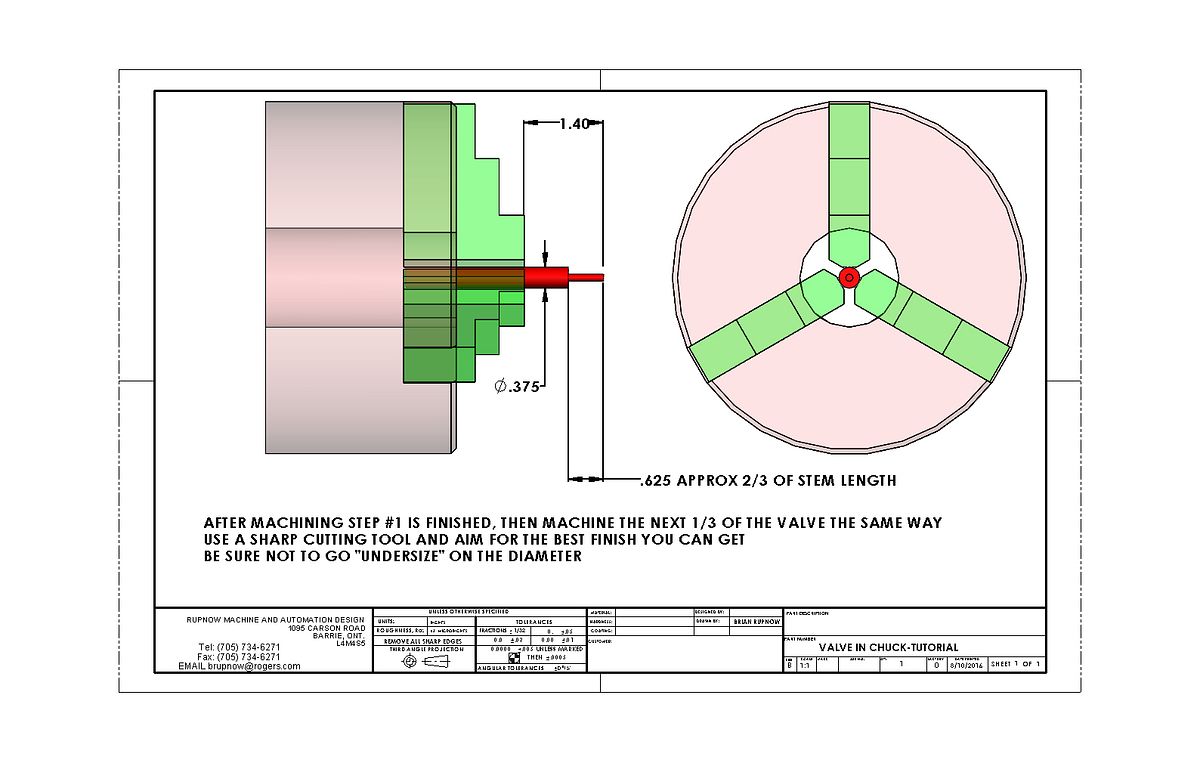
Now we are ready for our first actual machining step. Calculate the total length of the valve, and add 0.350" to it. That length of 1.40 will be the amount of material you want sticking out past the chuck jaws. We don't want to start our machining operation and then find out half way through that we haven't allowed ourselves enough "stick out" to work with. Deflection is our enemy here. If we try and turn down the full .938" length of the valve stem all in one go, we will find that the thin stem deflects quite dramatically, making it very difficult, even impossible to get a consistent diameter on the stem, which is very important. Divide the total length of the stem into 3 equal lengths, and machine the first third down to approx. .003" greater than the finished size. If you take off more, you risk going undersize, and having to start over again. If you leave more than .003" on there, you will make a ton of work for yourself when finessing the valve stem down to "finished size" with a strip of 220 grit carborundum paper.
 
After machining step #1 is finished, we move on to step #2, which is identical to step #1, except that this time we are going to machine the second third of the valve stem down to the same size as that in the first operation, again being very careful not to go "undersize and ruin things.
 
Machining step #3 is a repeat of the first two, with one major difference. This time, instead of turning to an "approximate third" of the length, we are going to turn to the actual dimension of .938" stem length.---and do be careful not to turn undersize. Use a cutting tool with a very small tip radius, because our next operation after this one is going to utilize the same tool and the topslide to form the face of the valve. We don't want a big radius where the tapered face runs into the stem (nor do we want to undercut the stem in the next operation.)
 
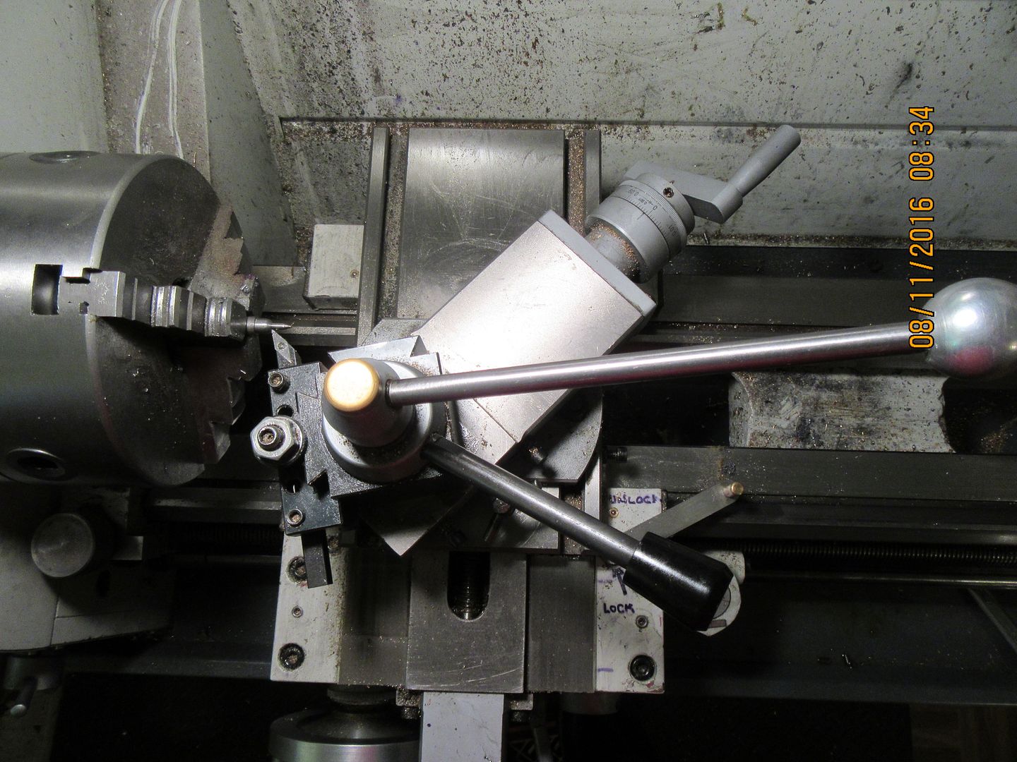
Now things begin to get a fit tricky. Remember that way back before we started this operation, we had swung the topslide around so the handle was at the far side of the lathe so that when we fed with the topslide it would cut the valve face to a 92 degrees included angle. Now is the time. Don't try and do it all in one bite. Take small cuts at a fairly high rpm (250 to 400 on my lathe) and don't back up too far while doing this and undercut the valve stem. Try for a very good finish on the valve face, because the better your finish is here, the better chance you have of your valve sealing properly on final assembly. There are two operations in this set-up. Now is when you get to use that "test fit" piece with the .125" hole reamed through it. Use a piece of 220 grit carborundum paper looped around the valve stem and with the lathe running at about 150 rpm, work the carborundum paper back and forth on only the stem portion of the valve, until it is a nice sliding fit into the hole in the test piece. We don't want it tight, or the valve springs won't pull the valves closed. We don't want it loose or the intake stroke will suck air between the valve cage and the stem. A GOOD sliding fit is what we need.
 
Last edited:
Now that the stem of the valve is brought down to the right size, and the angled face of the valve is finished, it is time to turn the head of the valve down to the right diameter. The drawing shows how we do that, and better yet explains why we do that.
 
At this point, we remove the valve from the chuck, take it over to the horizontal milling vice, and drill that tiny 0.040" diameter hole thru the end of the stem for the keeper pin. If doing this draws a burr, stick it back into the lathe and dress it a bit more with the 220 grit paper. Remember, it MUST slide thru that test block with the reamed hole in it freely.
Now you get to use the remaining 3/8" round material as a handle, which allows you to spin the valve back and forth with your fingers while lapping it into the 90 degree valve seat with first 400 grit, then 600 grit carborundum paste. The reason that the valve was cut with a 92 degree included taper is so that when you first begin to lap it into the seat, it forms a line contact with the top of the 90 degree coned seat. A bit of lapping very quickly matches the two lapped surfaces to give a perfect valve seal. I have tried to do this with the valve cut at a 90 degree included angle, and it simply doesn't seat and seal as well.
 
Last edited:
Now, finally, we can put the piece back into the 3 jaw on the lathe and part the valve off from the parent stock. If you feel a bit nervous about cutting the valve too short, then by all means cut it a bit too long and then flip it over, grip the stem of the valve in the 3 jaw, and carefully "face" it to length. It is pretty important to leave at least .020" of "land" above the taper to prevent the valves from "burning" from the heat of combustion.
 
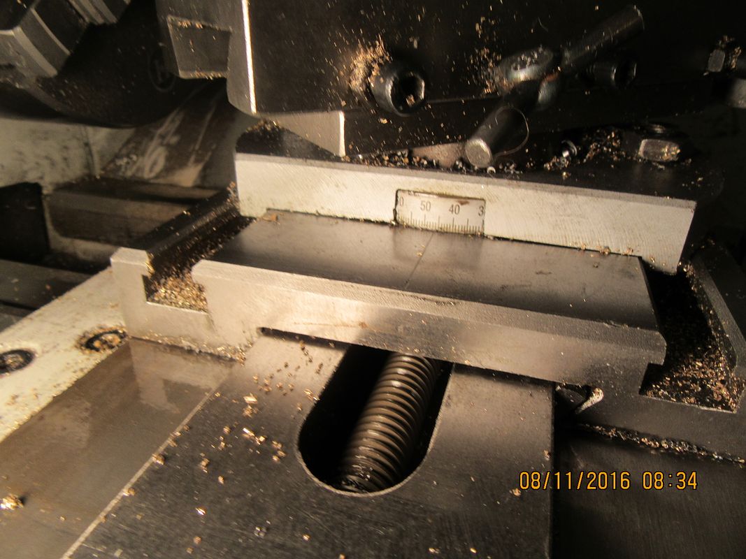
Here are a couple of rather shabby pictures showing what I mean by "turning the top slide so that the handle is on the far side of the lathe", set to cut an included face angle of 92 degrees. That is a real valve in the chuck, although it is one on which I accidently destroyed part of the stem while drilling the intake parts in my most recent engine. (yes, $hit happens to me too). In the picture, the stem has been brought down to the required diameter and the tool is poised in the position where it would be just before making the cut (using the topslide) to cut the valve face. Although the temptation is always there to just start cranking from that position and cut the face in one go, don't do it. There is too much material in that corner to take out in one cut. Take many small cuts from the stem towards the front of the lathe until the angled face is fully formed. Notice that the protractor is reading 46 degrees, which results in a 92 degree included angle on the valve face.

 
Thank you, Brian, for taking the time to draw this up and post it. I have saved it to my Webster build notes.

Found a couple of NGK CM-6 plugs today!

Chuck
 
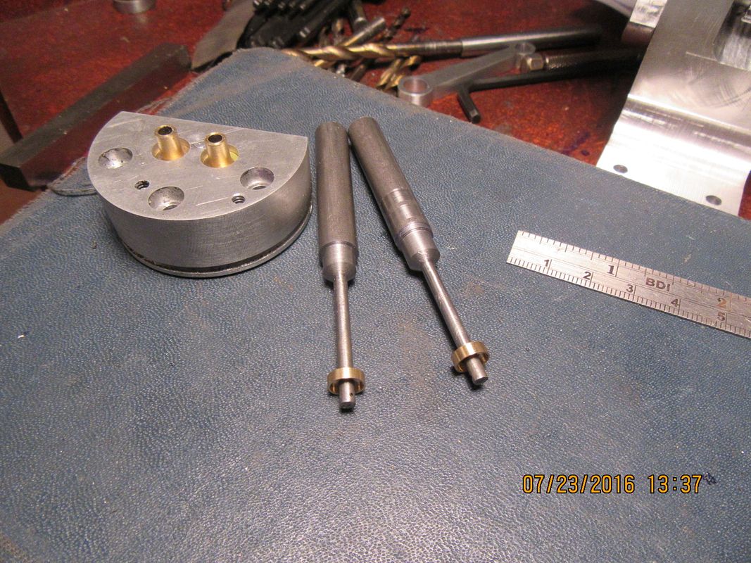
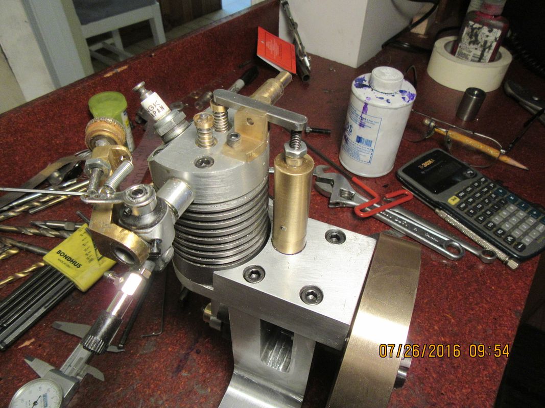
Here are a couple of the valves I made for my most recent engine. They are completely finished, except for being parted off from the "handles". Also shown in this picture are the brass "spring keepers" that slide over the end of the valves to keep the valve springs in place.
 
And here are the valves in their "home position" with springs and keepers in place. The valve with the rocker arm is cam driven. The other valve is an "atmospheric" valve that runs off engine vacuum alone.
 
Perfect timing and a great tutorial Brian. I was laying in bed last night trying to figure out the best way to make the valves. Logged on to this site this morning and there is my step by step guide. Greatly appreciated.
 
Herbie--I'm glad that worked out well for you. I was thinking of all the guys building my engine when I posted that.---Brian
 
Brian,

Even though I’m not ready to make any valves right now, I really appreciate the time you took to create this post. I’ve been following your work for quite a while and I’ve grasped each part of this technique as you developed it over the years. It’s so nice to see it all in one place.

Thanks again for all you have posted.

—ShopShoe
 
Thanks for the tutorial. It's good to see people's techniques for making parts.

...Ved.
 

Latest posts

Back
Top