All of our engines need a crankshaft. Crankshafts can be machined in one piece, or built up from separate sections of steel press fitted or Loctited and pinned together. If you do build a crankshaft and it is "true" with little run-out, then your flywheels won't wobble when the engine runs. I now build one piece crankshafts from 1144 stress proof steel, because it is very stable and will not change shape as it is machined. One piece crankshafts can be made from mild steel, or even from cold rolled steel, but as the metal is machined and internal stresses are relieved, they tend to end up changing shape as they are machined, and will not run true.
You are using an out of date browser. It may not display this or other websites correctly.
You should upgrade or use an alternative browser.
You should upgrade or use an alternative browser.
Making a one piece crankshaft from 1144 stress proof steel
- Thread starter Brian Rupnow
- Start date

Help Support Home Model Engine Machinist Forum:
This site may earn a commission from merchant affiliate
links, including eBay, Amazon, and others.
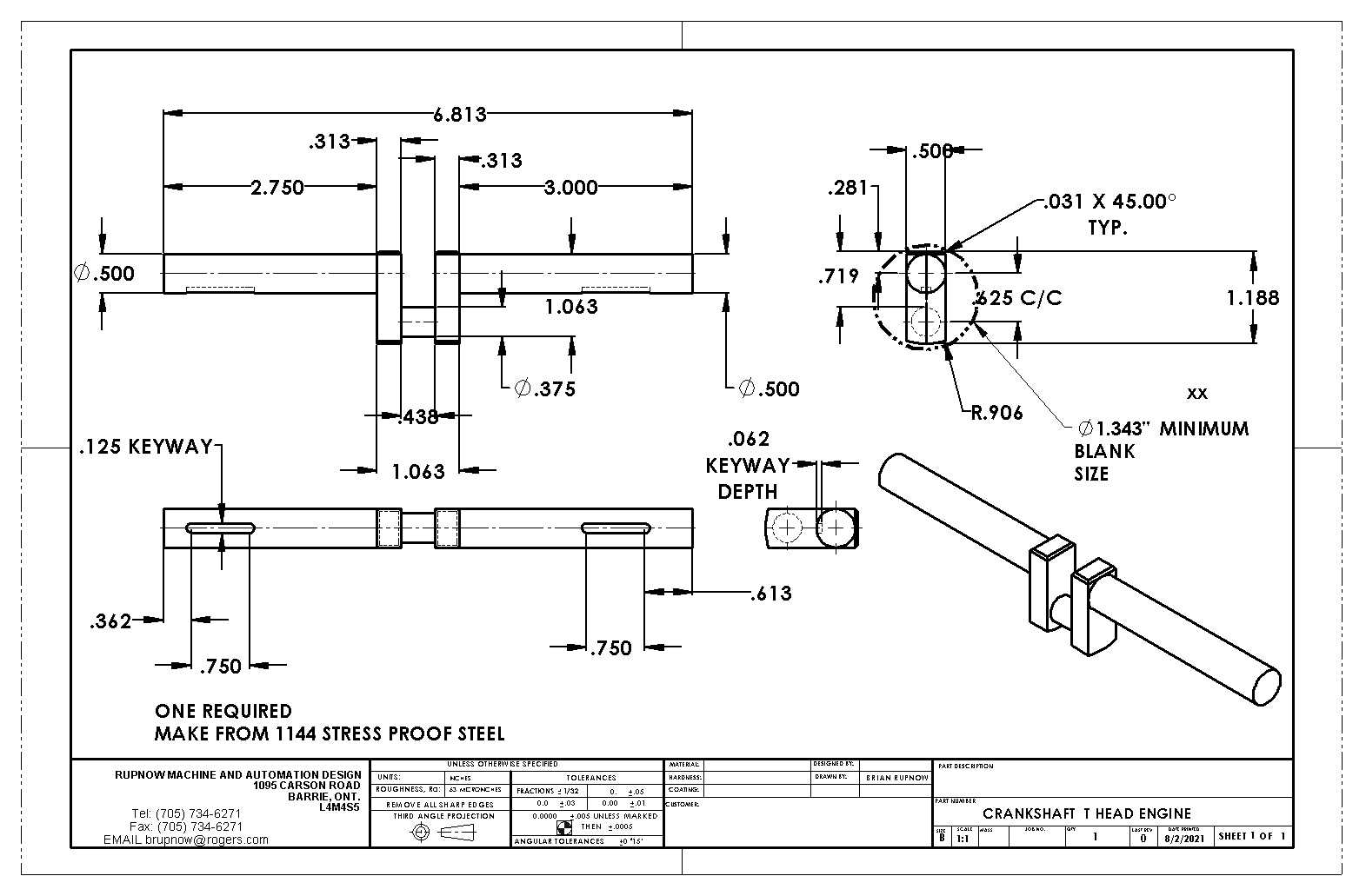
Stress proof steel is not available in flat bar that I know of, so the first step is to determine how large a piece of round 1144 you need to buy. You will have an end view of the crankshaft on the drawing you are working from, so you have to purchase a piece of 1144 large enough to encompass all of the crankshaft plus the "throw" which is the part which the connecting rod attaches to. Trust me, it's better to buy a piece a bit too large, than to try and pinch pennies by getting a smaller piece and finding out half way thru the machining that your material isn't large enough to machine in some of the features required.
I buy my 1144 steel locally from a metal supplier in Barrie, and the first thing you have to do is to machine a flat on one side to end up with a flat side to reference to when you are cutting off the other flat side. The best thing I can do here, is to use the crankshaft I built yesterday as an example. In the upper right hand view, you can see a dashed circle calling for a minimum 1.343" diameter blank size. In theory, I could have used a piece of 1 3/8" material, but all my steel supplier had in stock was 1 5/8", which was fine.

Last edited:
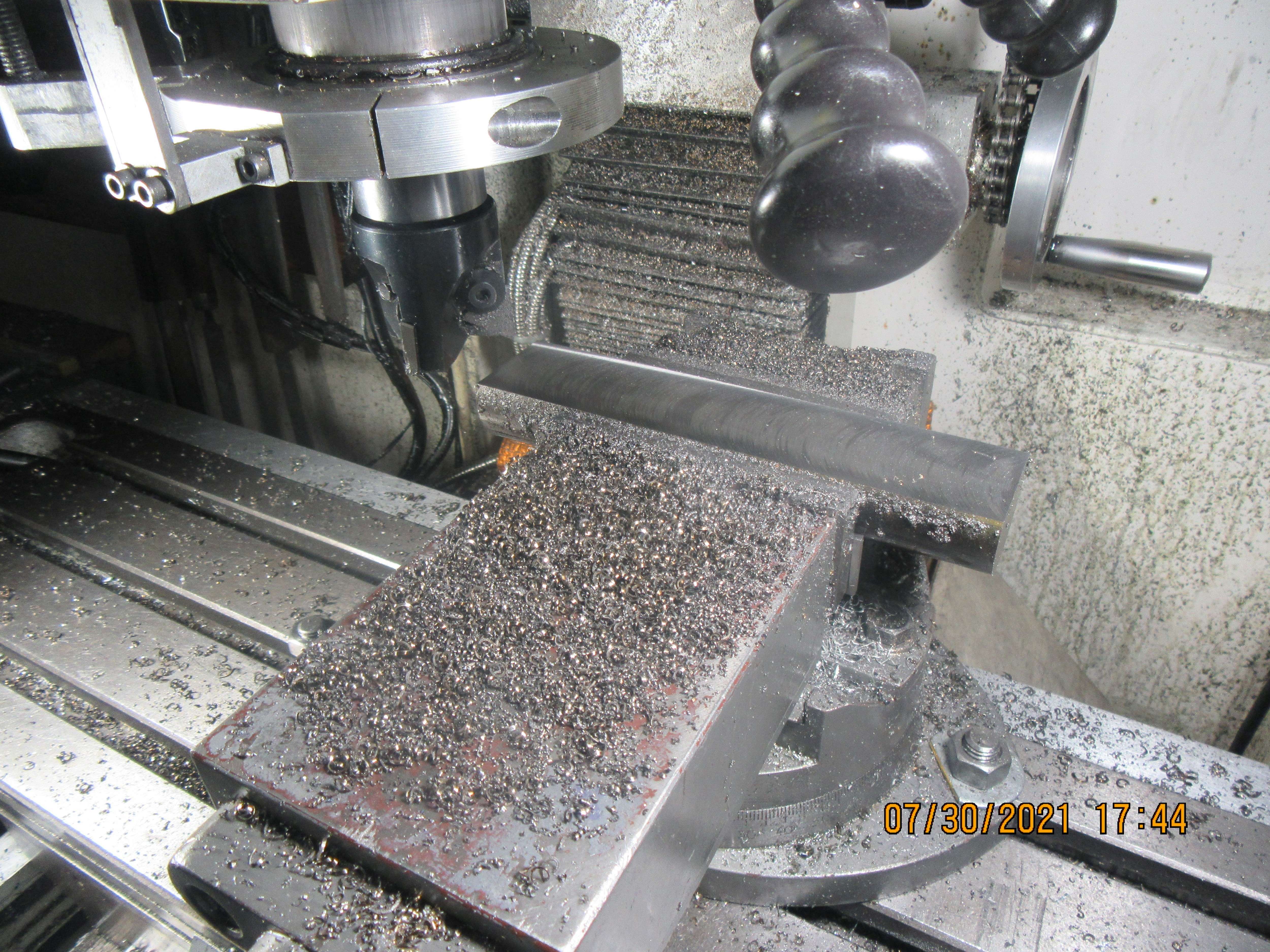
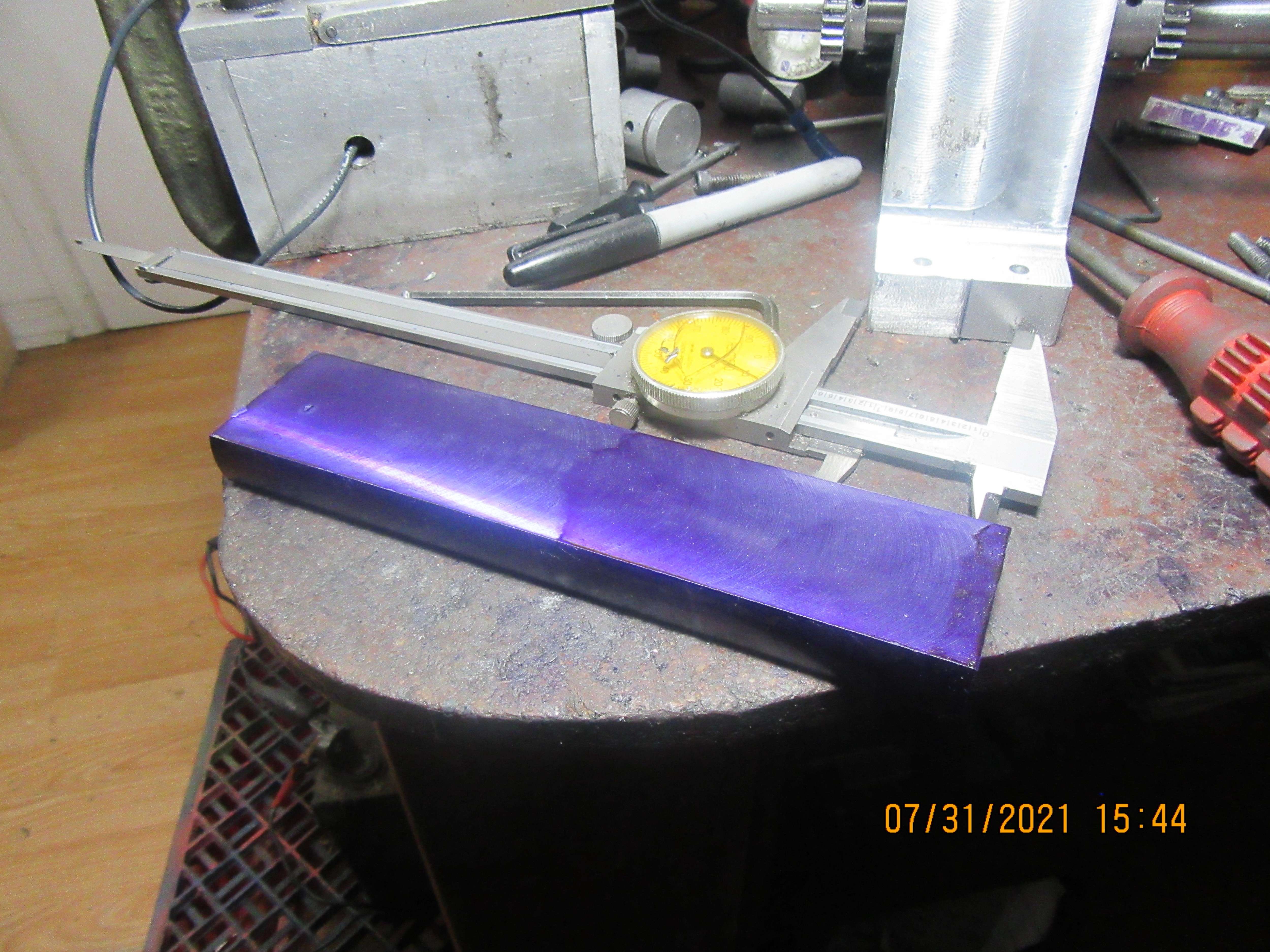
This is a picture of the 1 5/8" stock set up in my milling vice, with one side machined flat on it. ---A little math---The crankshaft maximum width is 0.500" We want to leave about 1/32" on each side of the minimum required width, so I wanted to be left with a 0.5625" wide slab of material. This meant that I had to machine 0.531" from each side of the round, to leave me with a slab 9/16" thick. I don't know of any good way to cut a slab from a round piece with any accuracy with my bandsaw, so the first step was to machine a flat. After the first side is machined flat, then you have a choice---You can put a fence on your bandsaw and referencing the flat side of the stock against the fence, you can saw off the second slab.---Or---You can machine the second side off. I used a 2" face mill and machined the second side off. A lot of cranking of mill handles, but I prefer the accuracy the milling machine gives me.


Last edited:
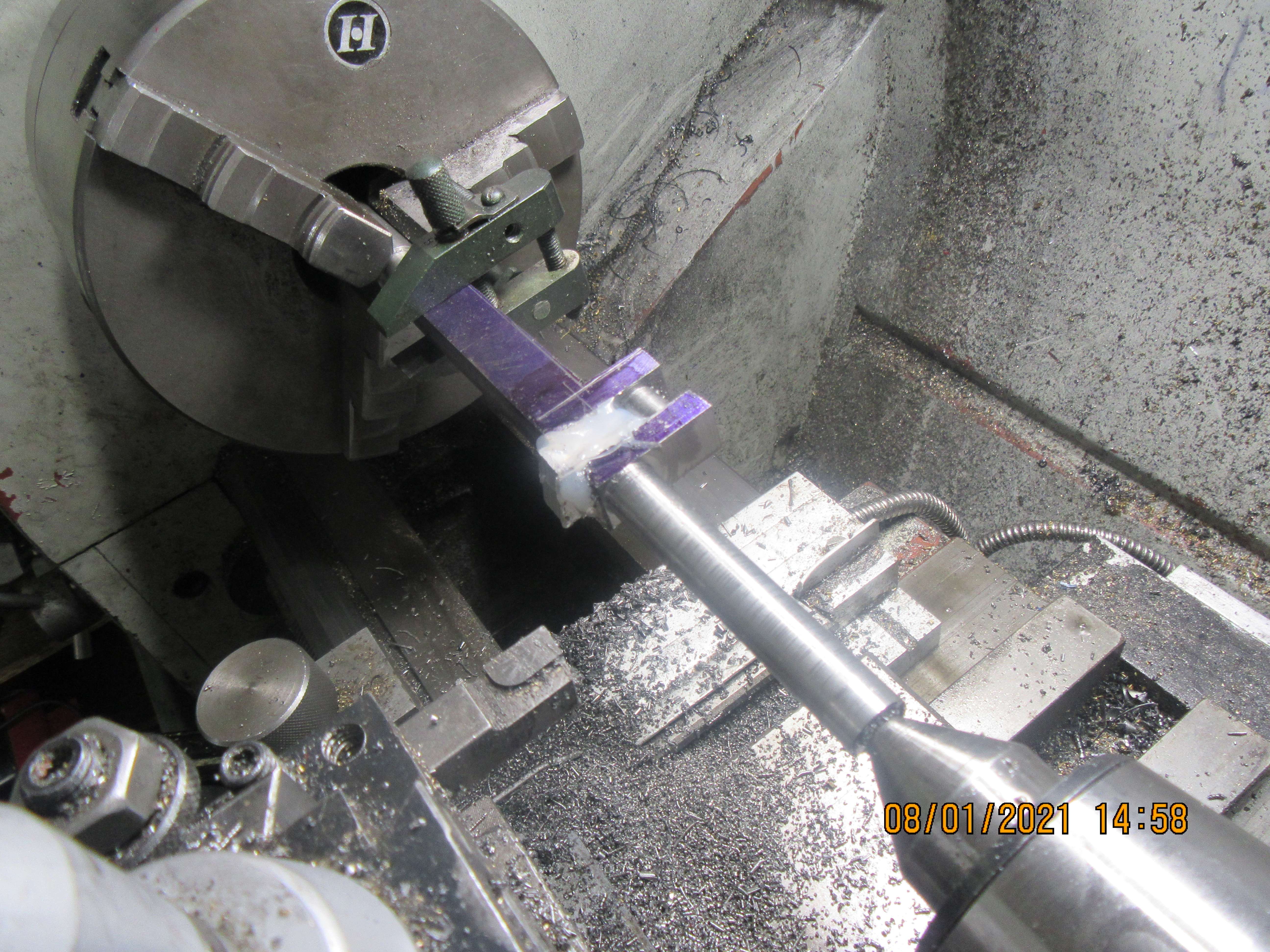
The stock is going to be turned between centers. Why?--Because the three jaw chuck on your lathe generally has about 0.003" Total indicated runout, and we don't want to transfer that runout to the crankshaft you are turning. Since this is going to require a center drill to be used on both ends of the stock, cut a length of stock about 3/4" longer than you actually need, so that when you are finished you can trim off the ends of the crankshaft that had the center drilled holes in them. Use a live center in the tailstock to support one end of the stock. At the chuck end, chuck a piece of 1/2" mild steel up and turn a point on it with a 120 degree included angle---Don't take it out of or reposition it in the chuck after turning it. The centerline of this turned piece will be truly in line with the centerline of your lathe. You can use a purchased lathe dog on the chuck end of the part you are going to turn, or you can use a machinists clamp as I did, with a couple of holes tapped in it for bolts which will be your drive dogs.

Last edited:
In the previous picture, I've skipped a couple of steps, but I wanted to show the part located between centers and driven by the lathe dog, and wanted to point out that you will machine the end closest to the tailstock. There won't be enough room between the tailstock and the chuck end to get your lathe saddle and cutting tool in there to cut next to the chuck end. In this picture above, you will see that the connecting rod journal has already been turned, and that a very accurately sized aluminum spacer has been slid into the gap, then glued in place with a glue gun. You have to machine this part to be a very accurate slide in fit. You must not force it into place, and you don't want a gap, so this filler piece is accurately machined for a nice sliding fit. It is put in there to keep the pressure of the tailstock center from springing the gap partially closed when it is tightened.
Now we go back to the steps I skipped past. This is very important, and is also the part with the biggest potential for disaster!!--Using the magic of 3D software, I can show the finished crankshaft "within" the piece of bar stock that it was cut from. First thing to note, is that the bar stock has two center drill marks in each end, that correspond with the centers of the crankshaft and with the rod journal. You can see that a portion of the stock has been removed with a sawcut. It could have been machined away in the lathe but it would take much longer to do.
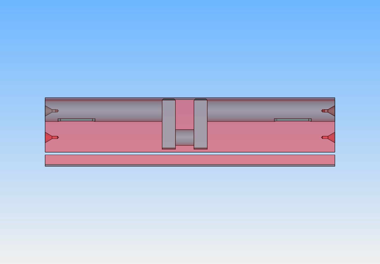

Last edited:
Next step is to remove a piece of the stock in what will become the space between the two cheek plates of the crankshaft. Leave enough material on that the machining will totally open the space between the cheek plates and leave enough material that you can machine a round con rod journal.
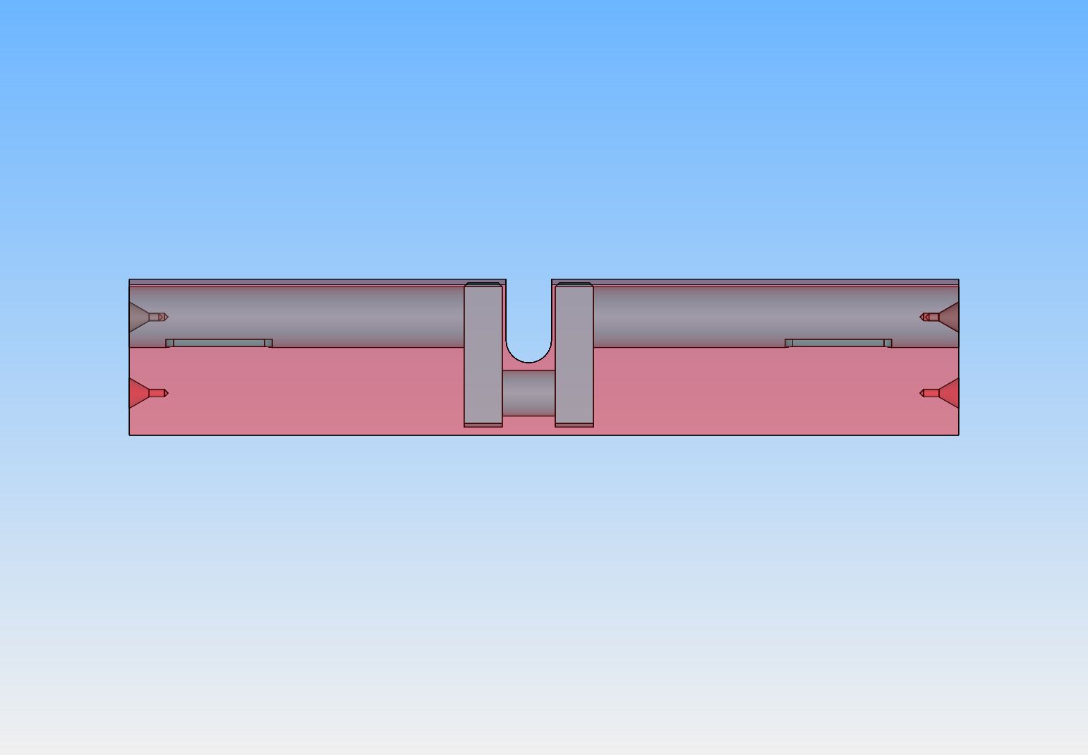
After machining the con rod journal you will be left with this.
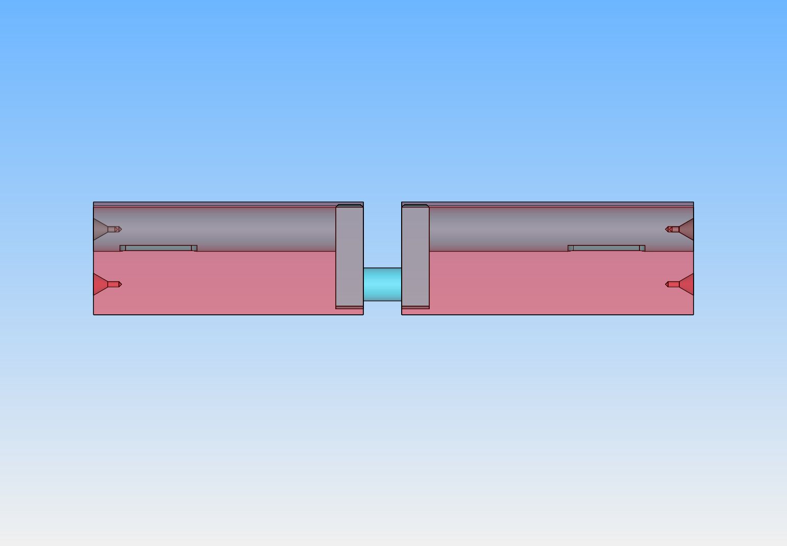

After machining the con rod journal you will be left with this.

Now that the con rod journal has been turned, you no longer need those center drilled ends, so you walk out to the bandsaw and saw away everything but this.--And for gosh sakes, don't cut in the wrong place!!
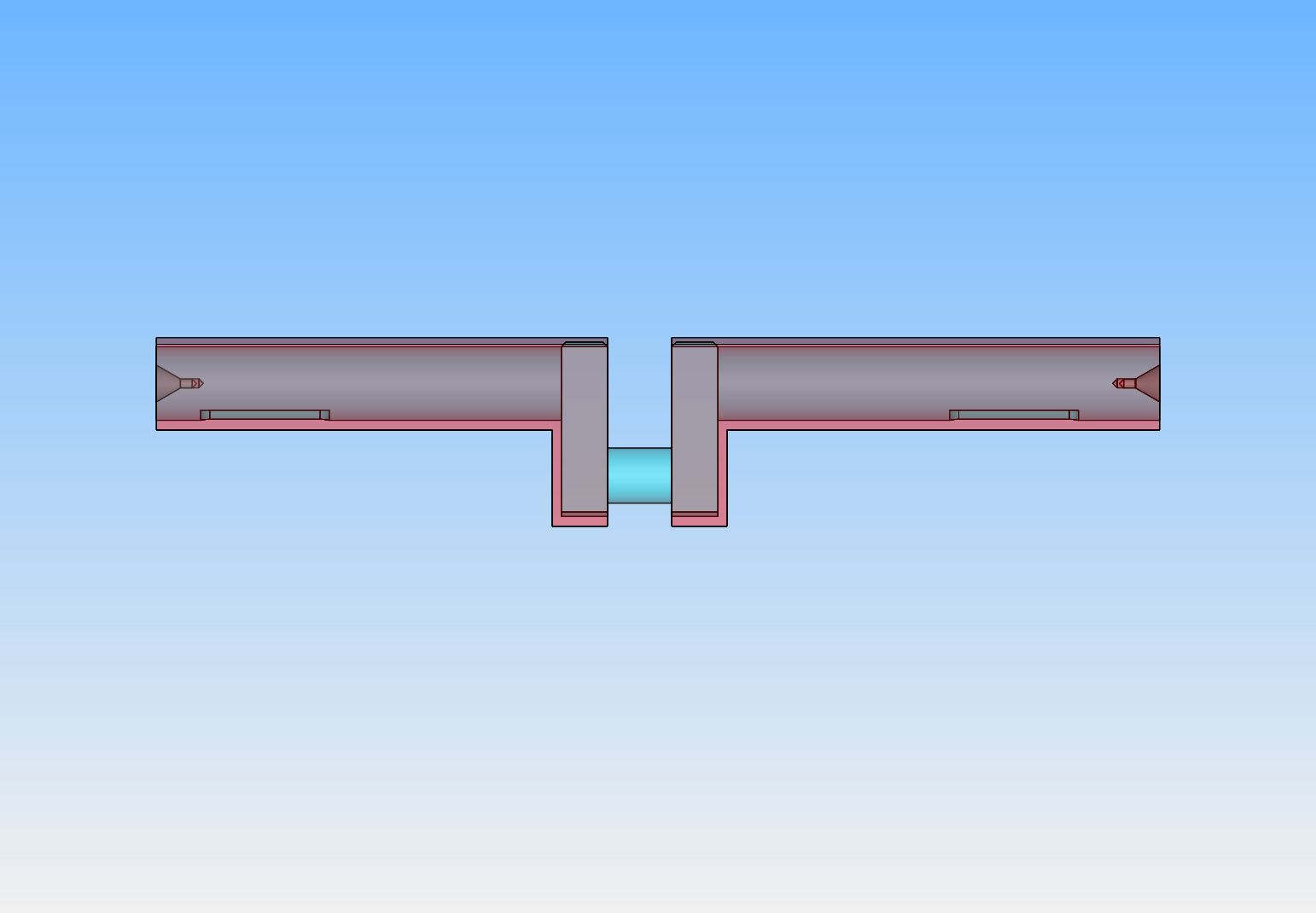

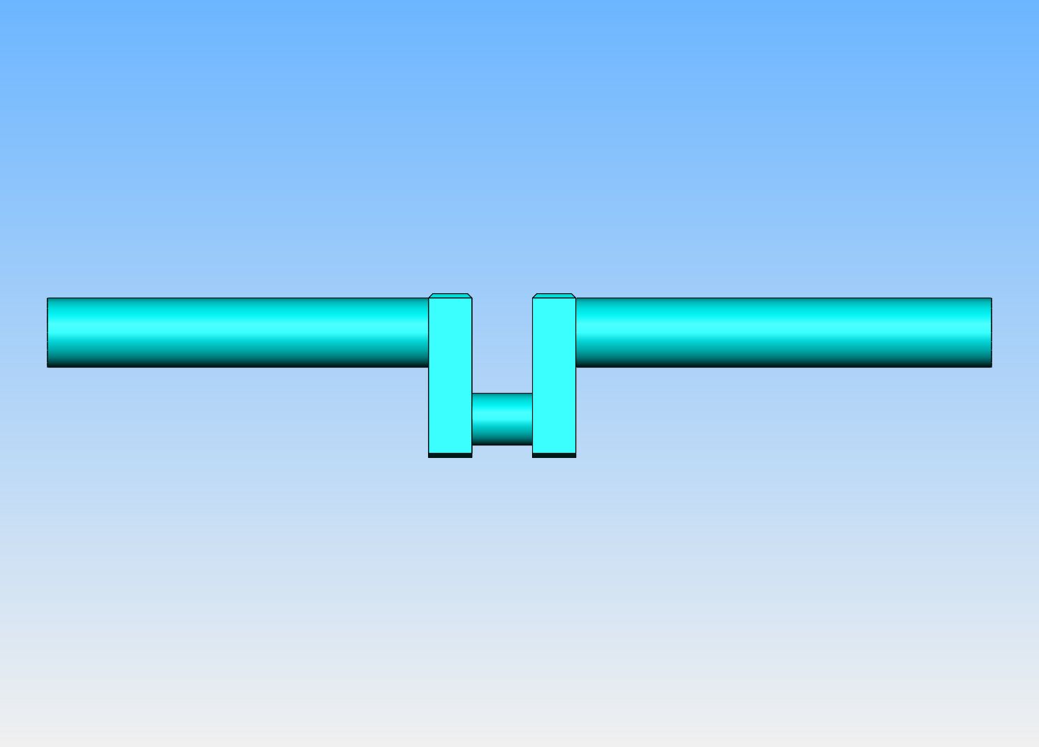
And finally, you use the second set of center drilled positions to mount the piece between centers and machine away everything else except for the crankshaft, then trim the ends off to get rid of the center drill marks, and you should have a crankshaft that will please the world.---Oh yes, when you go to machine the second half of the crankshaft, remove the crankshaft from the lathe and turn it end for end, then put the lathe dog on the finished end to you can machine the second end. Then you set it up in the milling vice and machine away that 1/32" of material that is still on the edges of the cheek plates. The keyways can be added later, when you are sure of where your flywheels are going to set. If you are going to add bolt on counterweights, now is a good time to drill and tap the cheek plates for the bolts which will hold the cheekplates on.

Last edited:
Very complete and well explained!
I have a short version for casual visitors to my workshop:
Start with a sufficiently large lump of steel, then cut off all the bits that don't look like a crankshaft.

I have a short version for casual visitors to my workshop:
Start with a sufficiently large lump of steel, then cut off all the bits that don't look like a crankshaft.
- Joined
- Jan 4, 2011
- Messages
- 1,418
- Reaction score
- 384
The biggest problem with making this is that it knocks the living daylights out of your lathe until the shaft and the journal gets to round. It is also difficult to get square corners on the crank shaft mount. The tool bit has to extend out for the depth of the throw.
Yes Gordon---There is a high pucker factor when machining the rod journal. I don't find it so bad now that I've made a few this way, but the first one sure makes your heart go pitter patter.
- Joined
- Jul 16, 2007
- Messages
- 3,028
- Reaction score
- 1,119
To avoid all the stress related to the intermittent cutting I first mill the rod slot leaving about .025 for cleanup. This way you only have a few corners to contend with.
Any tips for getting the centre drill holes in the correct spots? Obviously, the first set it easy as long as there is enough material left to machine the crank when it is mounted in the lathe with them. But how do you get the second set to be as parallel as possible with the first?
George--See the first picture in post #8. That is where I cut away most of the material on the rod slot before actually turning it in the lathe. mattb351--I just stand the piece on end in my mill vice , zero my edge finder out on the narrow side of the bar and put the two holes in line using the x axis feed on the mill. Then I flip the piece end for end and do the same again. Never had any problem with that.----Brian
Yes that makes sense now I think about it. The main errors to control would be 1/ the relative error between hole separation distance on each end and 2/ from the centrepoint of the holes on the ends not being coplanar. Using the mill means the error in distance between the holes on one end would also appear on the other end (due to leadscrew pitch error for instance) and using the same large face (that you milled earlier) against the vice would minimise the coplanar error. Any leadscrew pitch error would manifest itself as an error in crank throw which would be inconsequential even if it was 5 thou out. That would indeed be a bad leadscrew if it was 5 thou out over a few inches!
grahamgollar
Well-Known Member
I contemplated many options when producing a 3 throw crank for a triple expansion engine. One drawing showed a 'built up' crank comprising Ø3/8” round bar and 9/16" x 9/32" flats for the mains/ journals and webs respectively. This would have involved 13 individual components to be assembled securely and at 120 deg. This did not seem to be likely to succeed with accuracy and would not result in a crank of historical appearance.
I finally decided to machine the crank from Ø1.75" EN8 mild steel. The manufacture of various jigs was almost as time consuming as the machining of the crank but the finished unit was accurate within 0.005" axially and had webs more in keeping with traditional designs. It also had the advantage of incorporating a drive-end flange thus simplifying the mounting of the flywheel.
The photo below shows the (almost) finished crank which is 9.50" overall length. The flange at the near end is temporary, being one of the alignment jigs.


- Joined
- Aug 7, 2012
- Messages
- 14
- Reaction score
- 4
Hi Brian, excellent post as always. Could you tell us the name of your steel supplier in Barrie please?
I live in TO and have found the suppliers to be quite obnoxious about small orders and I end up buying from the US with huge freight charges.
A local supply might get me more active in my tiny workshop.
I live in TO and have found the suppliers to be quite obnoxious about small orders and I end up buying from the US with huge freight charges.
A local supply might get me more active in my tiny workshop.
A to Z Metals and Barrie Welding, are two very good sources of metal. A to Z is much cheaper than anybody, and very good to deal with.
Similar threads
- Replies
- 10
- Views
- 3K


