Machining Valve Stems

Home Model Engine Machinist Forum

Help Support Home Model Engine Machinist Forum:

This site may earn a commission from merchant affiliate links, including eBay, Amazon, and others.

Mike Ginn

Well-Known Member
HMEM Supporting Member
Joined
Mar 5, 2020
Messages
338
Reaction score
142
Location
UK
Please may I tap into the vast knowledge base of the HMEM members?

I need to machine the valves of the Kiwi and I can’t formulate a procedure which will give me a 1.5inch long x 0.125dia valve stem which is a good sliding fit into a reamed hole. I’m using silver steel (drill steel).

I could machine with a tail stock centre but there is little material for the centre drill and there would be bowing in the centre of the unsupported stem. I could machine to the diameter of 1/8 (from 3/8) in small steps but I would still need to take a final cut. I could fabricate but I have never heard of anyone doing that and I can’t believe it would work. I could rig up some sort of travelling steady but this would need to be adjusted for every cut – would work I guess.

So can you Guys suggest the preferred machining process to use?

Many thanks in advance

Mike
 
I would do it in 4 equal steps 3/8 long starting with the work piece protruding enough to turn the whole 1 1/2" without moving it. Go right to size on each step with a very small finish cut. Smooth any noticable joints with fine emory cloth held against something flat and hard. A tenth or 2 variation isn't going to hurt you.
 
Hi Mike .
1.5inch long x 0.125dia = 38 x 3.17 mm
I will do it your way. But I need a very sharp cutting tool - at least for the final cut + If necessary can change the lathe speed and feeds
Or..., I will use the grinder for the final step - I prefer this option.
 
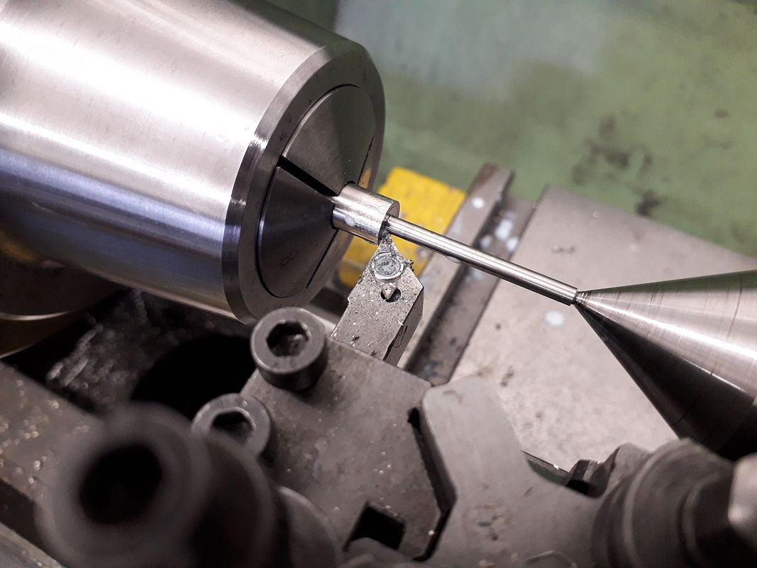
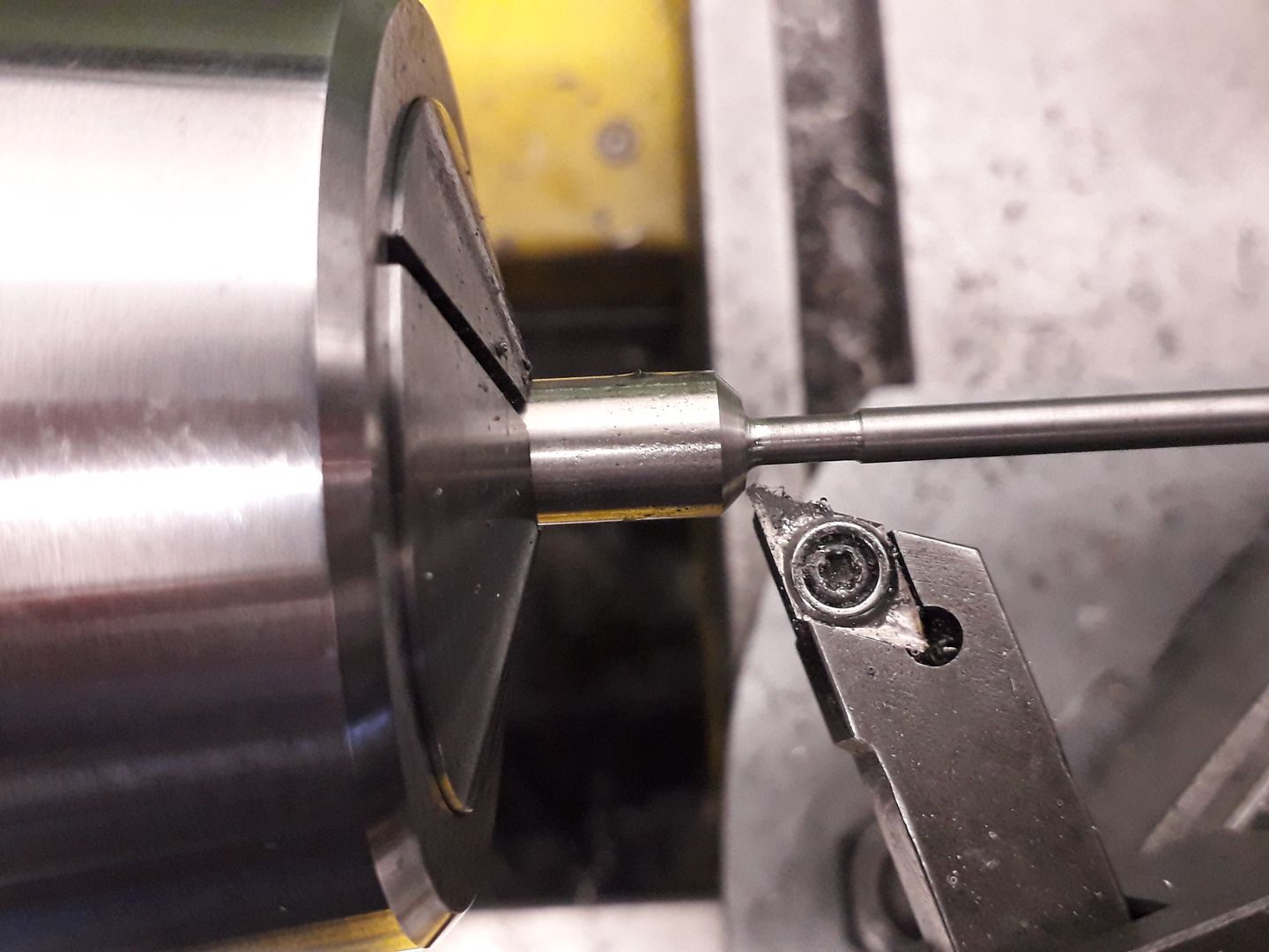
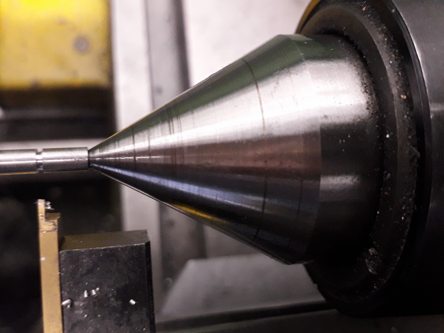
I tend to use 303 Stainless for valves and don't have a problem drilling the end with a BS0 ctr drill and turning with a DCGT insert, I leave the valve stem a little longer than needed then the ctr hole can be turned off by holding the finished valve in a collet. This is 3mm dia

20200208_094321_zpsvqlkglix.jpg


2.5mm dia behind the head

20190908_083128_zpszexxglsv.jpg


0.7mm wide clip groove

(edited)_20190908_090826_zpsxxi1lj4z.jpg
 
You will have no concerns about stem flex if you reverse the procedures describe previously here. You start with the valve head projecting out of the chuck. The valve stem is supported by the chuck. The head is supported by the live center when center drilled. Machine the stock behind the valve head to diameter length plus cut off. Cut in the 45 deg. valve face to the margin area. Part off.
I use 12L14 steel. It cuts as clean as brass with no lapping in for the mate to the valve guide. You have some lite duty stems there at eighth inch. I favor my models with 9/64th's!

1682048527795.png


1682048727000.png
 
Last edited:
Please may I tap into the vast knowledge base of the HMEM members?

I need to machine the valves of the Kiwi and I can’t formulate a procedure which will give me a 1.5inch long x 0.125dia valve stem which is a good sliding fit into a reamed hole. I’m using silver steel (drill steel).

I could machine with a tail stock centre but there is little material for the centre drill and there would be bowing in the centre of the unsupported stem. I could machine to the diameter of 1/8 (from 3/8) in small steps but I would still need to take a final cut. I could fabricate but I have never heard of anyone doing that and I can’t believe it would work. I could rig up some sort of travelling steady but this would need to be adjusted for every cut – would work I guess.

So can you Guys suggest the preferred machining process to use?

Many thanks in advance

Mike
I used the same method Andrew whale used on YouTube channel learning turning. A over sized disc with a 1/8th inch hole I tig welded the valve stem to the disc . Chucked it in a collet and smoothed the top off then machined the angle. Both valves worked fine.
 
I used the same method Andrew whale used on YouTube channel learning turning. A over sized disc with a 1/8th inch hole I tig welded the valve stem to the disc . Chucked it in a collet and smoothed the top off then machined the angle. Both valves worked fine.
For those of us that can't weld or have the equipment, that is an issue. Second unless the collet has absolutely zero run out there will need to be extensive lapping to get a seal against the valve seat.

Ron
 
Please may I tap into the vast knowledge base of the HMEM members?

I need to machine the valves of the Kiwi and I can’t formulate a procedure which will give me a 1.5inch long x 0.125dia valve stem which is a good sliding fit into a reamed hole. I’m using silver steel (drill steel).

I could machine with a tail stock centre but there is little material for the centre drill and there would be bowing in the centre of the unsupported stem. I could machine to the diameter of 1/8 (from 3/8) in small steps but I would still need to take a final cut. I could fabricate but I have never heard of anyone doing that and I can’t believe it would work. I could rig up some sort of travelling steady but this would need to be adjusted for every cut – would work I guess.

So can you Guys suggest the preferred machining process to use?

Many thanks in advance

Mike
For those of us that can't weld or have the equipment, that is an issue. Second unless the collet has absolutely zero run out there will need to be extensive lapping to get a seal against the valve seat.

Ron
Most should be able to silver solder . As far as lapping I had very little to do. It worked well for me.
 
I use to use a Box tool on a Hardinge Chucker to turn long small diameters. You could build one as they are pretty pricey to buy. I know Boyar-Schultz and Hardinge both mahe them. Handy tool to have around.
 

Attachments

  • Box Tool.jpg
    Box Tool.jpg
    51.7 KB
I always divide the stem into 4 or 5 sections and machine them to +.001 starting from the farthest from the chuck going to the nearest, then I switch to wet-or-dry, but always with light oil, and use 800 grit to get down to +.0004, then 1000 grit to get to +.0001, finally 2000 grit to hit the mark, then turn the paper over and use the paper side to get a mirror polish.

being precise about the final diameter is way overkill, since the second remedy for non-sealing valve seats is to enlarge the valve guide holes so the valve can adjust itself to the seat, but the mirror finish does make for good looking and smooth sliding valve stems.
 
You will have no concerns about stem flex if you reverse the procedures describe previously here. You start with the valve head projecting out of the chuck. The valve stem is supported by the chuck. The head is supported by the live center when center drilled. Machine the stock behind the valve head to diameter length plus cut off. Cut in the 45 deg. valve face to the margin area. Part off.
I use 12L14 steel. It cuts as clean as brass with no lapping in for the mate to the valve guide. You have some lite duty stems there at eighth inch. I favor my models with 9/64th's!

View attachment 146229

View attachment 146230
I agree completely with Longboy, here. Machine it with only one or two setups max to minimize run-out.

I seem to recall that the late George Luhrs made one-piece valves for his smallest engines that had 0.020" diameter stems. Someone asked him at Cabin Fever how he lapped them in . He replied that if the valve leaked after simply machining it, he threw it away and made another one...!
 
Thanks very much for the suggestions. There certainly are a number of diverse methods in use amongst the community.

This is my take on the methods and my reasoning: -

Several members use the step approach where each step is around 3/8ish. The final finish being via fine abrasive paper. Jason and Charles showed how tailstock support could be used and I guess that allowed for a final very fine cut to be made.

Longboy uses a reverse process with the head at the tailstock end. I would find this very difficult since there is no way to test the stem in the valve guide.

A Box tool was suggested. I have used one on a capstan but I think the amount of work involved in making a working Box for the Myford is too much. It does however introduce the concept of a form of travelling steady which was not mentioned by other members.

We next come to the fabrication methods. Putting the TIG method aside, that leaves silver soldering. Early on I dismissed this as “non workable” but some of you are having success with this method. I am warming to the idea! Its simple, ground drill rod clearly will fit my valve guide and I have no problem with my silver solder technique. I can extend the joint area and use a tailstock centre and finally hold in a collet to machine to length and remove the centre hole. I would need to be aware of distortion and not water quench. It does seem to be a good way forward.

As an added bonus, if it goes wrong, I can make another very quickly. Happy days!

Thanks for all your help – much appreciated

Mike
 
If you try silver solder I suggest a shoulder on the valve head and a good chamfer on both sides, don't fit the stem too tight so as to prevent the solder from flowing. Sometimes it's handy to put a center drilled pocket on the end of the valve stem before soldering. Use high silver content solder. I see some chinese vendors are selling those micro torches at a remarkably low price. I have a US one that really works well.
 
Thanks for that. I usually leave a 0.002 inch gap to allow for the flow. I have Johnson Mathey silver solder and a MAP torch so should work
Thanks
Mike
 
I didn't make a shoulder, but instead a little fixture to hold both the stem and cap.
Doug
 

Attachments

  • BF4EB7F7-F3E1-47D3-A5B3-30A20385CBC7.jpeg
    BF4EB7F7-F3E1-47D3-A5B3-30A20385CBC7.jpeg
    1.5 MB
  • 355E7381-FAAB-48D6-B2B5-63138C506681.jpeg
    355E7381-FAAB-48D6-B2B5-63138C506681.jpeg
    711.1 KB
  • B6523780-5BEF-48B7-B2D7-7C03E0C54089.jpeg
    B6523780-5BEF-48B7-B2D7-7C03E0C54089.jpeg
    1.7 MB
  • C3CA2F20-C035-4B93-9AC9-76A65D080925.jpeg
    C3CA2F20-C035-4B93-9AC9-76A65D080925.jpeg
    883.5 KB
Thanks very much for the suggestions. There certainly are a number of diverse methods in use amongst the community.

This is my take on the methods and my reasoning: -

Several members use the step approach where each step is around 3/8ish. The final finish being via fine abrasive paper. Jason and Charles showed how tailstock support could be used and I guess that allowed for a final very fine cut to be made.

Longboy uses a reverse process with the head at the tailstock end. I would find this very difficult since there is no way to test the stem in the valve guide.

A Box tool was suggested. I have used one on a capstan but I think the amount of work involved in making a working Box for the Myford is too much. It does however introduce the concept of a form of travelling steady which was not mentioned by other members.

We next come to the fabrication methods. Putting the TIG method aside, that leaves silver soldering. Early on I dismissed this as “non workable” but some of you are having success with this method. I am warming to the idea! Its simple, ground drill rod clearly will fit my valve guide and I have no problem with my silver solder technique. I can extend the joint area and use a tailstock centre and finally hold in a collet to machine to length and remove the centre hole. I would need to be aware of distortion and not water quench. It does seem to be a good way forward.

As an added bonus, if it goes wrong, I can make another very quickly. Happy days!

Thanks for all your help – much appreciated

Mike
You're welcome! If you're not familiar with George Luhr's astonishing craftsmanship, here is a link to his fully functional,1/8-inch bore, overhead-valve petrol engine:

https://craftsmanshipmuseum.com/artisan/george-luhrs/
 

Latest posts

Back
Top